CHRYSLER VOYAGER 1996 Service Manual
Manufacturer: CHRYSLER, Model Year: 1996, Model line: VOYAGER, Model: CHRYSLER VOYAGER 1996Pages: 1938, PDF Size: 55.84 MB
Page 421 of 1938

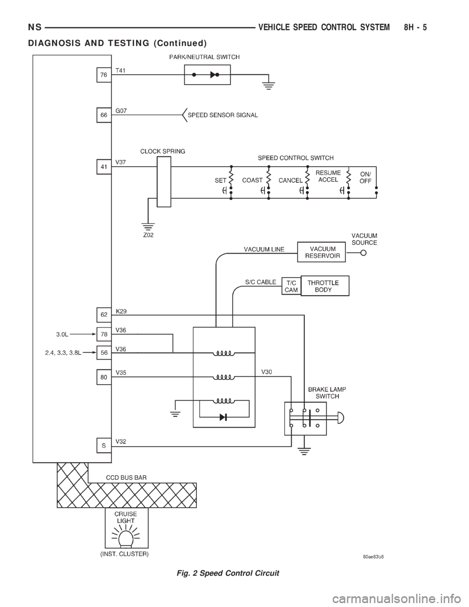
Fig. 2 Speed Control Circuit
NSVEHICLE SPEED CONTROL SYSTEM 8H - 5
DIAGNOSIS AND TESTING (Continued)
Page 422 of 1938

SERVO VACUUM TEST
(1) Turn ignition switch to the ON position with-
out starting engine. Activate speed control ON
switch.
(2) Disconnect the four-way electrical connector
and the vacuum harness at the servo (Fig. 3).
(3) Connect a jumper wire from Pin 3 of the servo
to Pin 3 of the wire connector.
(4) Ground Pins 2 and 4 in the servo. Do not con-
nect pin 1.
(5) Connect a hand held vacuum pump to the vac-
uum nipple and apply 10 - 15 inches of vacuum.
(6) If servo pulls cable, replace servo.
(7) Ground Pin 1 on servo.
(8) Check that the throttle cable pulls in and holds
as long as the vacuum pump is connected. After one
minute, check if cable is still holding. If cable does
not hold replace the servo.
(9) Disconnect jumper from pin 3. Cable should
return to rest position. If not, replace servo.
(10) Connect 4 way electrical connector and vac-
uum harness to servo.
SPEED CONTROL SWITCH TEST
Refer to the appropriate Powertrain Diagnostic
Manual for switch test valves.
STOP LAMP SWITCH TEST
(1) Remove the stop lamp switch refer to Stop
Switch Removal/Installation in this section. Discon-
nect connector from stop lamp switch (Fig. 4). Using
an ohmmeter, switch continuity may be checked as
follows:
(2) With switch plunger released, there should be
continuity between Pin 5 and Pin 6.(3) With switch plunger depressed, there should be
continuity:
²Between Pin 1 and Pin 2.
²Between Pin 3 and Pin 4.
(4) If the above results are not obtained, the stop
lamp switch is defective or out of adjustment.
(5) Stop lamp switch adjustment is detailed in
Group 5, Brakes.
ELECTRICAL TESTS AT POWERTRAIN CONTROL
MODULE
(1) Unplug the GRAY 40-way connector from the
Powertrain Control Module (PCM), (Fig. 5).
(2) Remove both steering wheel speed control
switches and disconnect the wire connectors.
Fig. 3 Servo Harness Connector
Fig. 4 Stop Lamp Wiring
Fig. 5 Powertrain Control Module Location
8H - 6 VEHICLE SPEED CONTROL SYSTEMNS
DIAGNOSIS AND TESTING (Continued)
Page 423 of 1938

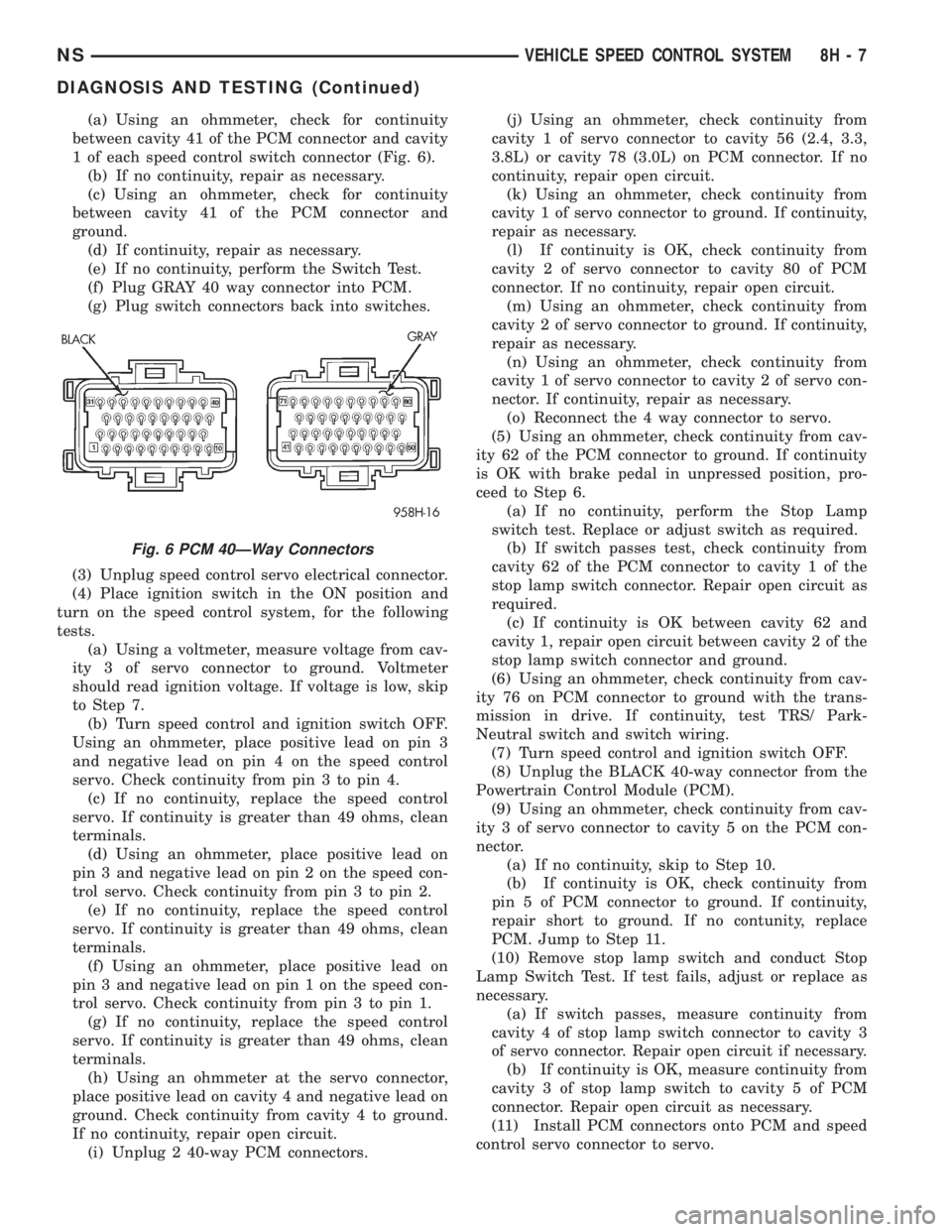
(a) Using an ohmmeter, check for continuity
between cavity 41 of the PCM connector and cavity
1 of each speed control switch connector (Fig. 6).
(b) If no continuity, repair as necessary.
(c) Using an ohmmeter, check for continuity
between cavity 41 of the PCM connector and
ground.
(d) If continuity, repair as necessary.
(e) If no continuity, perform the Switch Test.
(f) Plug GRAY 40 way connector into PCM.
(g) Plug switch connectors back into switches.
(3) Unplug speed control servo electrical connector.
(4) Place ignition switch in the ON position and
turn on the speed control system, for the following
tests.
(a) Using a voltmeter, measure voltage from cav-
ity 3 of servo connector to ground. Voltmeter
should read ignition voltage. If voltage is low, skip
to Step 7.
(b) Turn speed control and ignition switch OFF.
Using an ohmmeter, place positive lead on pin 3
and negative lead on pin 4 on the speed control
servo. Check continuity from pin 3 to pin 4.
(c) If no continuity, replace the speed control
servo. If continuity is greater than 49 ohms, clean
terminals.
(d) Using an ohmmeter, place positive lead on
pin 3 and negative lead on pin 2 on the speed con-
trol servo. Check continuity from pin 3 to pin 2.
(e) If no continuity, replace the speed control
servo. If continuity is greater than 49 ohms, clean
terminals.
(f) Using an ohmmeter, place positive lead on
pin 3 and negative lead on pin 1 on the speed con-
trol servo. Check continuity from pin 3 to pin 1.
(g) If no continuity, replace the speed control
servo. If continuity is greater than 49 ohms, clean
terminals.
(h) Using an ohmmeter at the servo connector,
place positive lead on cavity 4 and negative lead on
ground. Check continuity from cavity 4 to ground.
If no continuity, repair open circuit.
(i) Unplug 2 40-way PCM connectors.(j) Using an ohmmeter, check continuity from
cavity 1 of servo connector to cavity 56 (2.4, 3.3,
3.8L) or cavity 78 (3.0L) on PCM connector. If no
continuity, repair open circuit.
(k) Using an ohmmeter, check continuity from
cavity 1 of servo connector to ground. If continuity,
repair as necessary.
(l) If continuity is OK, check continuity from
cavity 2 of servo connector to cavity 80 of PCM
connector. If no continuity, repair open circuit.
(m) Using an ohmmeter, check continuity from
cavity 2 of servo connector to ground. If continuity,
repair as necessary.
(n) Using an ohmmeter, check continuity from
cavity 1 of servo connector to cavity 2 of servo con-
nector. If continuity, repair as necessary.
(o) Reconnect the 4 way connector to servo.
(5) Using an ohmmeter, check continuity from cav-
ity 62 of the PCM connector to ground. If continuity
is OK with brake pedal in unpressed position, pro-
ceed to Step 6.
(a) If no continuity, perform the Stop Lamp
switch test. Replace or adjust switch as required.
(b) If switch passes test, check continuity from
cavity 62 of the PCM connector to cavity 1 of the
stop lamp switch connector. Repair open circuit as
required.
(c) If continuity is OK between cavity 62 and
cavity 1, repair open circuit between cavity 2 of the
stop lamp switch connector and ground.
(6) Using an ohmmeter, check continuity from cav-
ity 76 on PCM connector to ground with the trans-
mission in drive. If continuity, test TRS/ Park-
Neutral switch and switch wiring.
(7) Turn speed control and ignition switch OFF.
(8) Unplug the BLACK 40-way connector from the
Powertrain Control Module (PCM).
(9) Using an ohmmeter, check continuity from cav-
ity 3 of servo connector to cavity 5 on the PCM con-
nector.
(a) If no continuity, skip to Step 10.
(b) If continuity is OK, check continuity from
pin 5 of PCM connector to ground. If continuity,
repair short to ground. If no contunity, replace
PCM. Jump to Step 11.
(10) Remove stop lamp switch and conduct Stop
Lamp Switch Test. If test fails, adjust or replace as
necessary.
(a) If switch passes, measure continuity from
cavity 4 of stop lamp switch connector to cavity 3
of servo connector. Repair open circuit if necessary.
(b) If continuity is OK, measure continuity from
cavity 3 of stop lamp switch to cavity 5 of PCM
connector. Repair open circuit as necessary.
(11) Install PCM connectors onto PCM and speed
control servo connector to servo.
Fig. 6 PCM 40ÐWay Connectors
NSVEHICLE SPEED CONTROL SYSTEM 8H - 7
DIAGNOSIS AND TESTING (Continued)
Page 424 of 1938

VACUUM SUPPLY TEST
(1) Disconnect vacuum hose at the servo and
install a vacuum gauge in the hose (Fig. 7).
(2) Start engine and observe gauge at idle. Vac-
uum gauge should read at least ten inches of mer-
cury. Shut off engine, the vacuum should continue to
hold 10 inches of mercury.
(3) If vacuum does not meet this requirement,
check and correct the following vacuum leaks in the
vacuum lines, check valve, vacuum reservoir or poor
engine performance.
VEHICLE SPEED SENSOR
For diagnosis and testing of the Vehicle Speed Sen-
sor (VSS), refer to the appropriate Powertrain Diag-
nostic Procedures service manual. Also refer to the
DRB scan tool.
REMOVAL AND INSTALLATION
SPEED CONTROL SERVO
REMOVAL
(1) Release hood latch and open hood.
(2) On vehicles with 3.3/3.8 L engine, remove air
cleaner resonator. Refer to Group 14, Fuel System for
proper procedure.
(3) Disconnect the throttle and speed control cable
ends from throttle body (Fig. 8).
(4) Depress lock tabs holding speed control cable
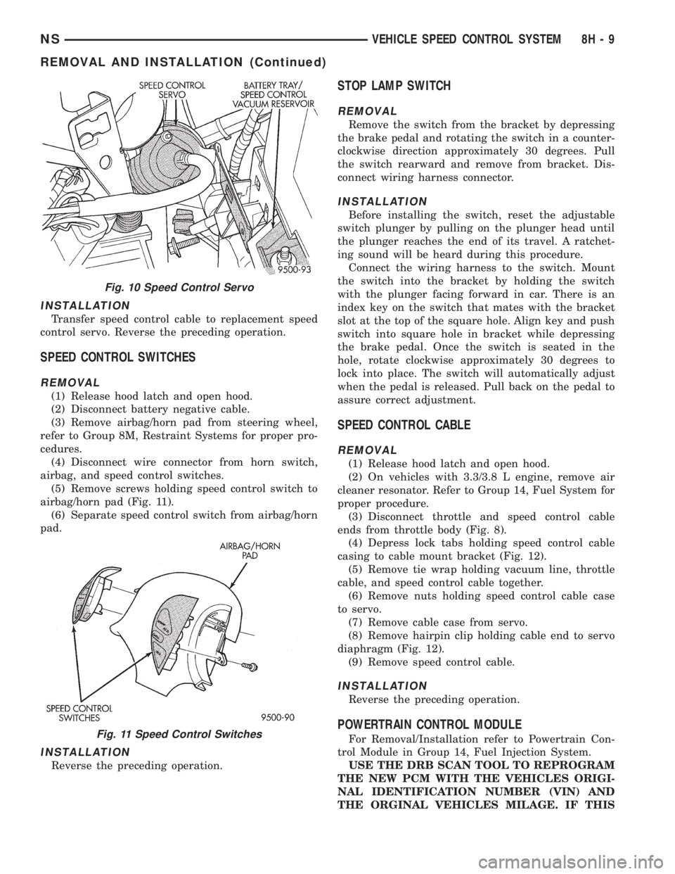
casing to cable mount bracket (Fig. 9).(5) Disconnect vacuum line from nipple on air
intake plenum.
(6) Remove tie wrap holding vacuum line, throttle
cable, and speed control cable together.
(7) Remove bolt holding speed control servo to side
of battery tray/vacuum reservoir (Fig. 10).
(8) Remove speed control servo from battery tray.
(9) Disconnect wire connector from speed control
servo.
(10) Disconnect vacuum line from speed control
servo that leads to the battery tray/vacuum reservoir.
(11) Remove speed control servo.
Fig. 7 Vacuum Gauge Test
Fig. 8 Speed Control Cable End
Fig. 9 Speed Control Cable Case and Vacuum
LineÐTypical
8H - 8 VEHICLE SPEED CONTROL SYSTEMNS
DIAGNOSIS AND TESTING (Continued)
Page 425 of 1938

INSTALLATION
Transfer speed control cable to replacement speed
control servo. Reverse the preceding operation.
SPEED CONTROL SWITCHES
REMOVAL
(1) Release hood latch and open hood.
(2) Disconnect battery negative cable.
(3) Remove airbag/horn pad from steering wheel,
refer to Group 8M, Restraint Systems for proper pro-
cedures.
(4) Disconnect wire connector from horn switch,
airbag, and speed control switches.
(5) Remove screws holding speed control switch to
airbag/horn pad (Fig. 11).
(6) Separate speed control switch from airbag/horn
pad.
INSTALLATION
Reverse the preceding operation.
STOP LAMP SWITCH
REMOVAL
Remove the switch from the bracket by depressing
the brake pedal and rotating the switch in a counter-
clockwise direction approximately 30 degrees. Pull
the switch rearward and remove from bracket. Dis-
connect wiring harness connector.
INSTALLATION
Before installing the switch, reset the adjustable
switch plunger by pulling on the plunger head until
the plunger reaches the end of its travel. A ratchet-
ing sound will be heard during this procedure.
Connect the wiring harness to the switch. Mount
the switch into the bracket by holding the switch
with the plunger facing forward in car. There is an
index key on the switch that mates with the bracket
slot at the top of the square hole. Align key and push
switch into square hole in bracket while depressing
the brake pedal. Once the switch is seated in the
hole, rotate clockwise approximately 30 degrees to
lock into place. The switch will automatically adjust
when the pedal is released. Pull back on the pedal to
assure correct adjustment.
SPEED CONTROL CABLE
REMOVAL
(1) Release hood latch and open hood.
(2) On vehicles with 3.3/3.8 L engine, remove air
cleaner resonator. Refer to Group 14, Fuel System for
proper procedure.
(3) Disconnect throttle and speed control cable
ends from throttle body (Fig. 8).
(4) Depress lock tabs holding speed control cable
casing to cable mount bracket (Fig. 12).
(5) Remove tie wrap holding vacuum line, throttle
cable, and speed control cable together.
(6) Remove nuts holding speed control cable case
to servo.
(7) Remove cable case from servo.
(8) Remove hairpin clip holding cable end to servo
diaphragm (Fig. 12).
(9) Remove speed control cable.
INSTALLATION
Reverse the preceding operation.
POWERTRAIN CONTROL MODULE
For Removal/Installation refer to Powertrain Con-
trol Module in Group 14, Fuel Injection System.
USE THE DRB SCAN TOOL TO REPROGRAM
THE NEW PCM WITH THE VEHICLES ORIGI-
NAL IDENTIFICATION NUMBER (VIN) AND
THE ORGINAL VEHICLES MILAGE. IF THIS
Fig. 10 Speed Control Servo
Fig. 11 Speed Control Switches
NSVEHICLE SPEED CONTROL SYSTEM 8H - 9
REMOVAL AND INSTALLATION (Continued)
Page 426 of 1938

STEP IS NOT DONE A DIAGONSTIC TROUBLE
CODE (DTC) MAY BE SET.
VACUUM RESEROIR
REMOVAL
(1) Disconnect negative cable from battery.
(2) Remove battery, Refer to Group 8B, for Battery
Removal/Installation
(3) Remove battery tray.
(4) Disconnect vacuum hoses from vacuum reser-
voir
INSTALLATION
(1) Connect vacuum hoses to vacuum reservoir.
(2) Install battery tray
(3) Install battery, Refer to Group 8B, for Battery
Removal/Installation.
(4) Connect negative cable to battery.
VEHICLE SPEED SENSOR
For Removal/Installation, refer to Vehicle Speed
Sensor in Group 14, Fuel Injections.
Fig. 12 Speed Control Cable
8H - 10 VEHICLE SPEED CONTROL SYSTEMNS
REMOVAL AND INSTALLATION (Continued)
Page 427 of 1938

VEHICLE SPEED CONTROL SYSTEM
CONTENTS
page
GENERAL INFORMATION
INTRODUCTION........................ 1
GENERAL INFORMATION
INTRODUCTION
This group covers both Left-Hand Drive (LHD) and
Right-Hand Drive (RHD) versions of this model.
Whenever feasible, the RHD versions of affected
vehicle components have been constructed as mirror-
image of the LHD versions. While most of the illus-
trations used in this group represent only the LHD
version, the diagnostic and service procedures out-
lined can generally be applied to either version.
Exceptions to this rule have been clearly identified as
LHD or RHD, if a special illustration or procedure
was/is required.
The speed control system used with the 2.5L diesel
engine is basically identical to the system used with
gasoline powered engines. Features unique to the
diesel engine will be covered in this section.
²Models equipped with the 2.5L diesel engine do
not use a vacuum reservoir to retain engine vacuum
for speed control operation. There are no vaccum-op-
erated speed control servos used in vehicles with the
2.5L diesel engine.
²The range of the speed control system operation
is restricted to speeds between 56 km/h (35 MPH) to
145 km/h (90 MPH).
²Inputs to the MSA that allow speed control oper-
ation are from the vehicle speed sensor and the
Speed Control Switch.²Two separate speed control switch modules are
mounted on the steering wheel to the left and right
side of the driver's airbag module. Switch features
are:
a. Within the two switch modules, fivemomen-
tarycontact switches, supporting seven different
speed control functions are used.
b. The outputs from these switches are filtered
into one input. The MSA determines which output
has been applied throughresistive multiplexing.
The input circuit voltage is measured by the MSA
to determine which switch function has been
selected.
c. A speed control indicator lamp, located on the
instrument panel cluster is energized by the MSA
via the CCD Bus. This occurs when speed control
system power has been turned ON, and the engine
is running.
d. The two switch modules are labeled: ON/OFF,
SET, RESUME/ACCEL, CANCEL and COAST.
Refer to the owner's manual for more information
on speed control switch functions and setting pro-
cedures. The individual switches cannot be
repaired. If one individual switch fails, the switch
module must be replaced.
NS/GSVEHICLE SPEED CONTROL SYSTEM 8H - 1
Page 428 of 1938

Page 429 of 1938

TURN SIGNAL AND FLASHERS
CONTENTS
page page
GENERAL INFORMATION
COMBINATION FLASHER.................. 1
INTRODUCTION......................... 1
DESCRIPTION AND OPERATION
COMBINATION FLASHER / DAYTIME
RUNNING LAMPS (DRL) MODULE......... 2
COMBINATION FLASHER FUNCTION......... 1DIAGNOSIS AND TESTING
COMBINATION FLASHER WITH / WITHOUT
DAYTIME RUNNING LAMPS MODULEÐ
CIRCUIT DIAGNOSTICS.................. 3
TURN SIGNAL MULTI-FUNCTION SWITCH.... 2
REMOVAL AND INSTALLATION
COMBINATION FLASHER WITH / WITHOUT
DRL MODULE........................ 11
MULTI-FUNCTION SWITCH............... 11
GENERAL INFORMATION
INTRODUCTION
The turn signals are actuated with a lever on the
left side of the steering column just ahead of the
steering wheel. The signals are automatically turned
off by a canceling cam (two lobes molded to the clock-
spring mechanism). The cam comes in contact with
the cancel actuator on the turn signal (multi-func-
tion) switch assembly. Either cam lobe, pushing on
the cancel actuator, returns the switch to the OFF
position.
Lane change signaling is actuated by applying par-
tial turn signal stalk movement toward the direction
desired until the indicator lamps flashes in the
instrument cluster. When the switch stalk is released
the stalk will spring back into the neutral position
turning OFF the turn signal.
With the ignition switch ON and the turn signal
switch stalk actuated left or right, current flows
through the:
²Combination flasher
²Multi-function switch
²Turn indicator lamp
²Front and rear turn signal bulbs.
A chime will sound after the vehicle has traveled a
distance of approximately 0.5 mile with the turn sig-
nal ON.
COMBINATION FLASHER
The Turn Signal/Hazard Warning Flasher is a
module providing the vehicle with turn signal and
hazard warning functions and has been designed
with internal relays to take advantage of low current
switching requirements in the vehicle. It is plugged
into the Junction Block at position 4 (Fig. 1), where
all wiring associated with its operation is terminated.The Junction Block is adjacent to and left of the
steering column of the vehicle.
To gain access to the flasher, remove the lower
steering column cover and knee blocker. Refer to
Group 8E, Instrument Panel and Systems for
removal procedures.
DESCRIPTION AND OPERATION
COMBINATION FLASHER FUNCTION
The Turn Signal/Hazard Warning Flasher is a
module providing turn signal, hazard warning func-
tions and has been designed with internal relays to
Fig. 1 Combination Flasher Location
NSTURN SIGNAL AND FLASHERS 8J - 1
Page 430 of 1938

take advantage of low current switching require-
ments in the vehicle. It is plugged into the Junction
Block at positions 4 (Fig. 1) where all wiring associ-
ated with its operation is terminated. The Junction
Block is adjacent to and left of the steering column of
the vehicle.
To gain access to the device, remove the lower
steering column cover and knee blocker, refer to
Group 8E, Instrument Panel and Systems.
The combination flasher may be operated in its
hazard warning mode either with or without the igni-
tion circuit being active. However, in order to operate
in the turn signal mode, the ignition circuit must be
completed to the module.
While the combination flasher is idle, there is no
current drawn through the module. The device does
not become active until a signal ground circuit is
supplied to either of the turn signal inputs or the
hazard warning input.
Typical flash rate for the flasher is 90 flashes per
minute.
When a lamp is burnt out for a given side of the
vehicle or a wire is open to a lamp, the flash rate will
increase to 180 flashes per minute when in the turn
signal mode. When in the hazard warning signal
mode the flash rate remains at 90 flashes per
minute.
Turn signal inputs that actuate the flasher are low
current grounds, each drawing a maximum of 300
mA., and are provided to the flasher through the
Junction Block from the multi-function switch that is
mounted to the steering column. The hazard warning
signal input is a low current ground drawing a max-
imum of 600 mA. through the multi-function switch.
COMBINATION FLASHER / DAYTIME RUNNING
LAMPS (DRL) MODULE
The Combination Flasher/DRL is a module provid-
ing turn signal, hazard warning, and daytime run-
ning light functions, and has been designed with
internal relays to take advantage of low current
switching requirements in the vehicle. It is plugged
into the junction block at positions 3 AND 4 (Fig. 2)
where all wiring associated with its operation is ter-
minated. The Junction Block is adjacent to and left of
the steering column of the vehicle.
To gain access to the device, remove the lower
steering column cover and knee blocker, refer to
Group 8E, Instrument Panel and Gauges.
The combination flasher/DRL may be operated in
its hazard warning mode either with or without the
ignition circuit being active. However, in order to
operate in the turn signal mode or the DRL mode,
the ignition circuit must be completed to the module.
While the combination flasher portion is idle, there
is no current drawn through the module. The devicedoes not become active in the turn signal or hazard
warning modes until a signal ground circuit is sup-
plied to either of the turn signal inputs or the hazard
warning input. With the ignition OFF, there is no
current drawn through the module.
While the ignition is ON, the front turn signal fil-
aments are illuminated steadily thus providing the
DRL function. The DRL function may be inhibited by
applying a signal ground input from either the park
brake circuit or the headlamp relay activation circuit.
Typical flash rate for the flasher is 90 flashes per
minute.
When a lamp is burnt out for a given side of the
vehicle or a wire is open to a lamp, the flash rate will
increase to 180 flashes per minute when in the turn
signal mode. When in the hazard warning signal
mode the flash rate remains at 90 flashes per
minute.
Turn signal inputs that actuate the flasher are low
current grounds, each could draw a maximum of 300
mA., and are provided to the flasher through the
Junction Block from the multi-function switch that is
mounted to the steering column. The hazard warning
signal input is a low current ground that could draw
a maximum of 600 mA. through the multi-function
switch.
DIAGNOSIS AND TESTING
TURN SIGNAL MULTI-FUNCTION SWITCH
To test turn signal, headlamp beam select and opti-
cal horn portion of the multi-function switch:
(1) Remove the multi-function switch, refer to
removal procedures.
(2) Using an ohmmeter check continuity reading
between multi-function switch pins. Refer to (Fig. 3)
for proper pin numbers and Turn Signal Multi-Func-
tion Switch Test chart.
Fig. 2 Junction Block Terminal Pins
8J - 2 TURN SIGNAL AND FLASHERSNS
DESCRIPTION AND OPERATION (Continued)