lock DATSUN 210 1979 Workshop Manual
[x] Cancel search | Manufacturer: DATSUN, Model Year: 1979, Model line: 210, Model: DATSUN 210 1979Pages: 548, PDF Size: 28.66 MB
Page 207 of 548
are
clean
and
free
from
foreign
matter
Cearance
between
cylinder
bore
and
piston
Leu
than
0
15
mm
0
0059
in
ASSEMBLY
Assemble
clutch
master
cylinder
in
the
reverse
order
of
disassembly
Ob
serve
the
following
I
Dip
piston
cup
in
brake
fluid
before
installing
Make
sure
that
it
is
correctly
faced
in
position
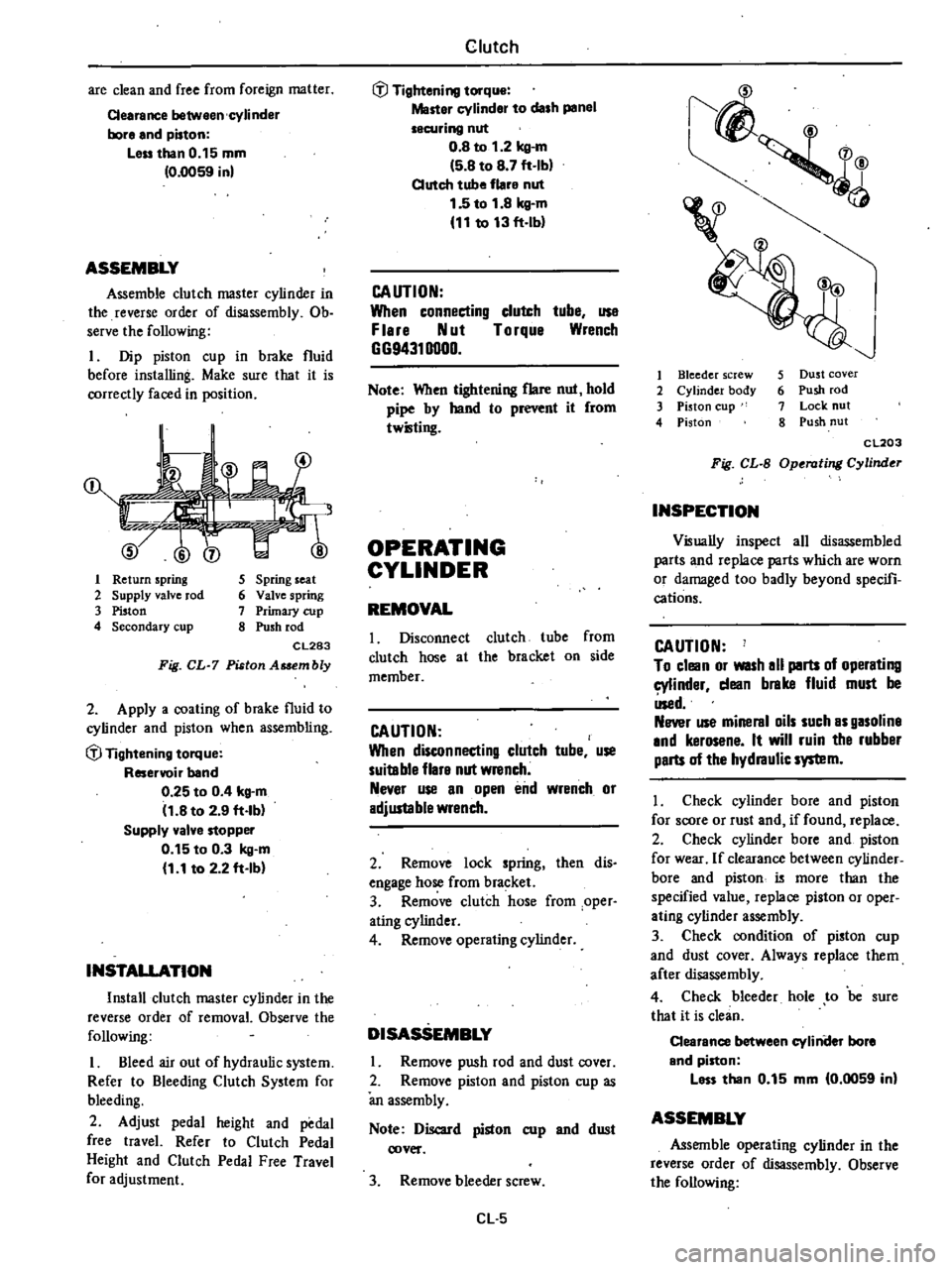
1
Return
spring
2
Supply
valve
rod
3
Piston
4
Secondary
cup
5
Spring
seat
6
Valve
spring
7
Primary
cup
8
Push
rod
CL283
Fig
CL
7
Piston
Asaembly
2
Apply
a
coating
of
brake
fluid
to
cylinder
and
piston
when
assembling
if
Tightening
torque
Reservoir
band
0
25
to
0
4
kg
m
11
8
to
2
9
ft
lb
Supply
valve
stopper
0
15
to
0
3
kg
m
1
1
to
2
2
ft
Ib
INSTALLATION
Install
clutch
master
cylinder
in
the
reverse
order
of
removal
Observe
the
following
I
Bleed
air
out
of
hydraulic
system
Refer
to
Bleeding
Clutch
System
for
bleeding
2
Adjust
pedal
height
and
pedal
free
travel
Refer
to
Clutch
Pedal
Height
and
Clutch
Pedal
Free
Travel
for
adjustment
Clutch
if
Tightening
torque
Master
cylinder
to
dash
panel
securing
nut
0
8
to
1
2
kg
m
5
8
to
8
7
ft
Ib
Clutch
tube
flare
nut
1
5
to
1
8
kg
m
11
to
13
ft
lb
CAUTION
When
connecting
clutch
tube
use
F
lere
Nut
Torque
Wrench
GG94310000
Note
When
tightening
flare
nut
hold
pipe
by
hand
to
r
it
from
twilling
OPERATING
CYLINDER
REMOVAL
I
Disconnect
clutch
tube
from
clutch
hose
at
the
bracket
on
side
member
CAUTION
When
disconnecting
clutch
tube
use
suitable
flare
nut
wrench
Never
use
an
open
end
wrench
or
adjustable
wrench
2
Remove
lock
spring
then
dis
engage
hose
from
bracket
3
Remove
clutch
hose
from
oper
ating
cylinder
4
Remove
operating
cylinder
DISASSEMBLY
Remove
push
rod
and
dust
cover
2
Remove
piston
and
piston
cup
as
an
assembly
Note
Discard
piston
cup
and
dust
cover
3
Remove
bleeder
screw
Cl
5
1
4
v
I
Bleeder
screw
2
Cylinder
body
3
Piston
cup
4
Piston
5
Dust
cover
6
Push
rod
7
Lock
nut
8
Push
nut
CL203
Fig
CL
B
Operating
Cylinder
INSPECTION
Visually
inspect
all
disassembled
parts
and
replace
parts
which
are
worn
or
damaged
too
badly
beyond
specifi
cations
CAUTION
To
clean
or
WISh
all
parts
of
operating
cylinder
dean
brake
fluid
must
be
Used
Never
use
mineral
oils
such
as
gasoline
and
kerosene
It
will
ruin
the
rubber
parts
of
the
hydraulic
system
I
Check
cylinder
bore
and
piston
for
score
or
rust
and
if
found
replace
2
Check
cylinder
bore
and
piston
for
wear
If
clearance
between
cylinder
bore
and
piston
i5
more
than
the
specified
value
replace
piston
or
oper
ating
cylinder
assembly
3
Check
condition
of
piston
cup
and
dust
cover
Always
replace
them
after
disassembly
4
Check
bleeder
hole
to
be
sure
that
it
is
clean
Clearance
between
cyliniler
bore
and
piston
less
than
0
15
mm
0
0059
in
ASSEMBLY
Assemble
operating
cylinder
in
the
reverse
order
of
disassembly
Observe
the
following
Page 208 of 548
t
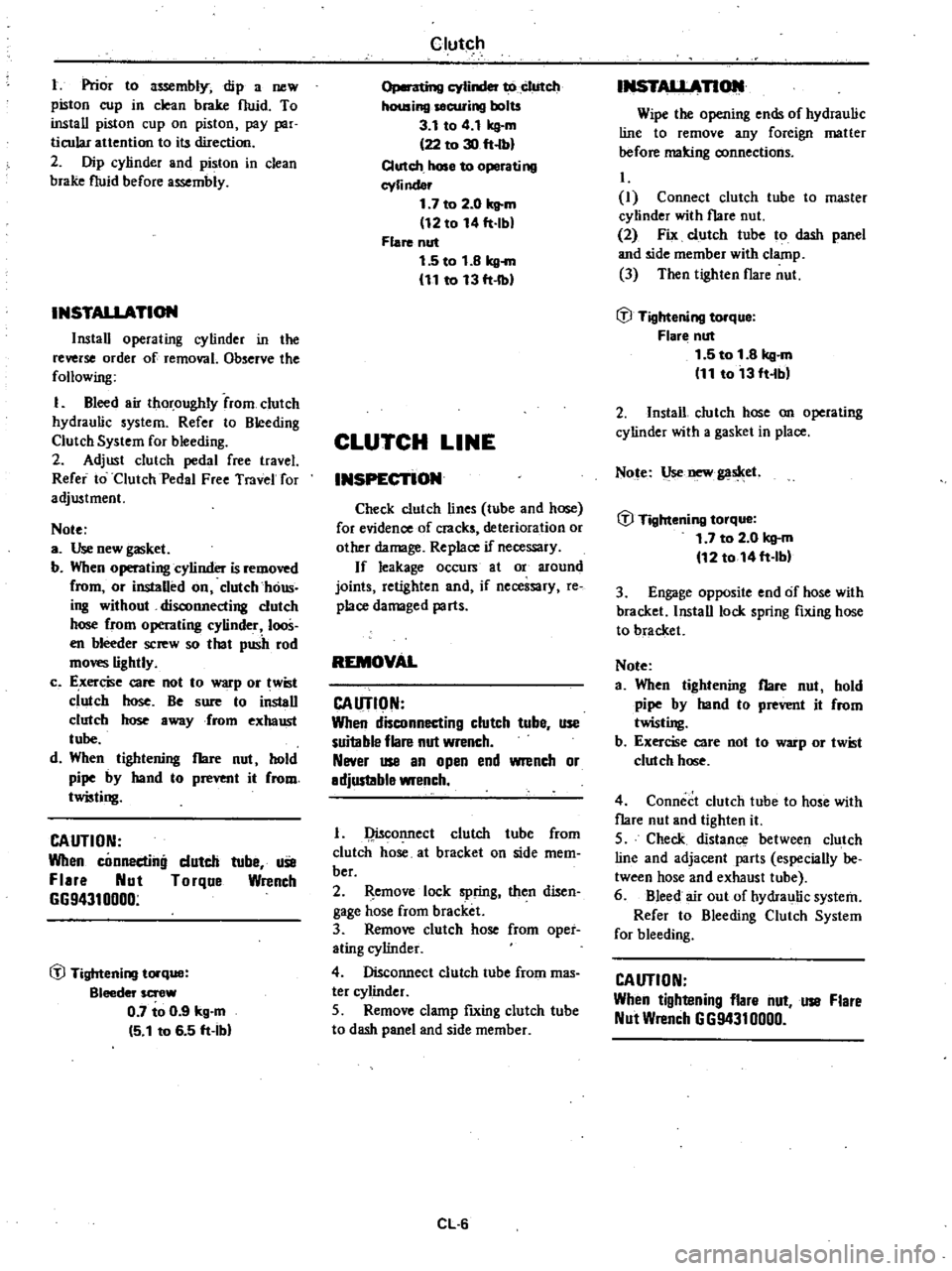
Prior
to
lWembly
dip
a
new
piston
cup
in
clean
brake
fluid
To
install
piston
cup
on
piston
pay
par
ticular
auention
to
its
direction
2
Dip
cylinder
and
piston
in
clean
brake
fluid
before
assembly
INSTALLATION
Install
operating
cylinder
in
the
reverse
order
of
removal
Observe
the
following
1
Bleed
air
thoroughly
from
clutch
hydraulic
system
Refer
to
Bleeding
Clutch
System
for
bleeding
2
Adjust
clutch
pedal
free
travel
Refer
to
Clutch
Pedal
Free
Travel
for
adjustment
Note
a
Use
new
gasket
b
When
operating
cylinder
is
removed
from
or
instaUed
on
clutch
haus
ing
without
disconnecting
clutch
hose
from
operating
cylinder
loos
en
bleeder
screw
so
that
push
rod
mo
lightly
c
E
xer
e
care
not
to
p
or
wist
clutch
hose
Be
sure
to
install
clutch
hose
away
from
exhaust
tube
d
When
tightening
flare
nut
hold
pipe
by
hand
to
prevent
it
from
twisting
CAUTION
When
connecting
dutch
tuhe
uSe
Flare
Nut
Torque
Wrench
G694310000
@
Tightening
torque
Bleeder
screw
0
7
to
0
9
kg
m
5
1
to
6
5
ft
Ihl
Clutch
o
cylinder
to
clutch
housing
securing
bolts
3
1
to
4
1
kg
m
22
to
30
ft
lbl
Clutch
hose
to
operating
cyli
nder
1
7
to
2
0
kg
m
12
to
14
ft
lbl
Flare
nut
1
5
to
1
8
kg
m
11
to
13
ft
Ibl
CLUTCH
LINE
INSPECTION
Check
clutch
lines
tube
and
hose
for
evidence
of
cracks
deterioration
or
other
damage
Replace
if
necessary
If
leakage
occurs
at
or
around
joints
retighten
and
if
necessary
re
place
damaged
parts
REMOVAL
CAUTION
When
disconnecting
clutch
tube
use
suitable
flare
nut
wrench
Never
use
an
open
end
wrench
or
adjustable
wrench
1
Qisconnect
clutch
tube
from
clutch
hose
at
bracket
on
side
mem
ber
2
emove
lock
spring
then
disen
gage
hose
from
bracket
3
Remove
clutch
hose
from
oper
ating
cylinder
4
Disconnect
clutch
tube
from
mas
ter
cylinder
5
Remove
clamp
fIxing
clutch
tube
to
dash
panel
and
side
member
CL
6
INSTALLAnOlll
Wipe
the
opening
ends
of
hydraulic
line
to
remove
any
foreign
matter
before
malting
connections
I
Connect
clutch
tuhe
to
master
cylinder
with
flare
nut
2
Fix
clutch
tube
to
dash
panel
and
side
member
with
clamp
3
Then
tighten
flare
nut
@
Tightening
torque
Flar
nut
1
5
to
1
8
kg
m
11
to
13
ft
Ibl
2
InstaU
clutch
hose
on
operating
cylinder
with
a
gasket
in
place
Note
Use
new
gaslcet
@
Tightening
torque
1
7
to
2
0
kg
m
12
to
14ft
lbl
3
Engage
opposite
end
of
hose
with
bracket
InstaU
lock
spring
fIxing
hose
to
bracket
Note
a
When
tightening
flare
nut
hold
pipe
by
hand
to
prevent
it
from
twisting
b
Exercise
care
not
to
warp
or
twist
clu1ch
hose
4
Connect
clutch
tube
to
hose
with
flare
nut
and
tighten
it
5
Check
distance
between
clutch
line
and
adjacent
parts
especially
be
tween
hose
and
exhaust
tube
6
Bleed
air
out
of
hydraulic
system
Refer
to
Bleeding
Clutch
System
for
bleeding
CAUTION
When
tightening
flare
nut
use
Flare
Nut
Wrench
G
G9431
0000
Page 213 of 548

Clutch
Clutch
cover
Diaphragm
spring
height
mm
in
Unevenness
of
diaphragm
spnng
toe
height
mm
in
29
0
to
31
0
1
142
to
1
220
Less
than
O
5
0
020
TIGHTENING
TORQUE
Pedal
stopper
lock
nut
Master
cylinder
push
rod
lock
nut
Operating
cylinder
push
rod
lock
nut
Operating
cylinder
bleeder
screw
Master
cylinder
to
dash
panel
securing
nut
kg
m
ft
lb
Clutch
tube
flare
nut
kg
m
ft
Ib
kg
m
ft
b
kg
m
ft
Ib
kg
m
ft
b
kg
m
ft
b
0
8
to
1
2
5
8
to
8
7
0
8
to
1
2
5
8
to
8
7
0
8
to
1
2
5
8
to
8
7
0
7
to
0
9
5
1
to
6
5
0
8
to
1
2
5
8
to
8
7
1
5
to
1
8
11
to
13
Operating
cylinder
to
clutch
housing
securing
bolt
Qutch
hose
to
operating
cylinder
Qutch
cover
bolt
kg
m
ft
lb
kg
m
ft
Ib
kg
m
ft
Ib
3
1
to
4
1
22
to
30
17
to
2
0
12
to
14
1
6
to
2
1
12
to
15
CL
11
Page 219 of 548

I
ht
2nd
fork
r
2
3rd
top
fork
rod
3
Reverse
fork
rod
4
Retaining
pin
5
I
t
2nd
shift
fork
6
3rd
top
shift
fork
7
Checking
ball
plug
8
Check
ban
spring
9
Check
ball
10
Interlock
plunger
11
S
topper
ring
12
Shift
rod
A
bracket
13
Reverse
shift
fork
14
Lock
pin
15
Striking
lever
Manual
Transmission
16
Striking
rod
17
Return
spring
plug
18
Reverse
check
spring
19
Return
pring
20
Plunger
21
D
ring
22
Stopper
pin
bolt
23
Striking
guide
assembly
24
Striking
guide
oil
seal
REMOVAL
To
dismount
transmission
from
the
car
proceed
as
follows
Disconnect
battery
ground
cable
2
Remove
console
box
and
detach
rubber
boots
if
so
equipped
3
Place
transmission
control
lever
in
neutral
position
and
remove
it
m
TM781
Fig
MT
4
Removing
Control
Lever
@
@
25
Control
lever
bushing
26
Expansion
plug
27
Control
pin
bushing
28
Control
arm
pin
29
Control
lever
o
Tightening
torque
kg
m
ft
lb
@
0
5
to
0
8
3
6
tn
5
8
@
1
3
to
1
7
9
to
12
Fig
MT
3
F4W60L
Tra11lmiBSion
Shift
Control
Components
TM094A
4
Jack
up
the
car
and
support
its
weight
on
safety
stands
Use
a
hy
draulic
hoist
or
open
pit
if
available
Make
sure
that
safety
is
insured
5
Disconnect
front
exhaust
tube
and
remove
bolt
securing
exhaust
mounting
bracket
from
exhaust
front
tube
side
6
Disconnect
wires
from
reverse
back
up
lamp
switch
7
Disconnect
speedometer
cable
from
rear
extension
At
the
same
time
removey
top
detecting
switch
if
so
equipped
8
Remove
propeller
shaft
Refer
to
Removal
Section
PO
Note
Plug
up
the
opening
in
the
rear
extension
to
prevent
oil
from
flow
ing
out
MT
3
9
Remove
clutch
operating
cylinder
from
transmission
case
10
Support
engine
by
placing
a
jack
under
oil
pan
with
a
wooden
block
used
between
oil
pan
and
jack
CAUTION
00
not
place
the
jack
under
the
oil
pan
drain
plug
11
Support
transmission
with
a
transmission
jack
12
Loosen
rear
engine
mount
se
curing
bolts
CD
temporarily
and
re
move
crossmember
mounting
bolts
V
Page 221 of 548
DISASSEMBLY
TRANSMISSION
CASE
DISASSEMBLY
I
Prior
to
disassembling
traiIsmis
sian
thoroughly
wipe
off
dirt
and
grease
from
it
2
Drain
oil
thoroughly
3
Remove
dust
cover
from
trans
mission
case
Remove
release
bearing
and
with
drawallever
4
Remove
reverse
lamp
switch
and
top
detecting
switch
if
equipped
5
Remove
speedometer
pinion
as
sembly
6
Remove
nut
and
stopper
pin
bolt
from
rear
end
of
rear
extension
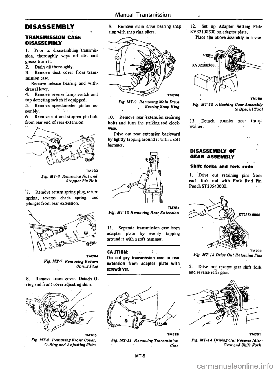
TM783
Fig
MT
6
Removing
Nut
and
Stopper
Pin
Bolt
7
Remove
return
spring
plug
return
spring
reverse
check
spring
and
plunger
from
rear
extension
@
@
j
TM784
Fig
MT
7
Rt
moving
Return
Spring
Plug
8
Remove
front
cover
Detach
0
ring
and
front
cover
adjusting
shim
TM785
Fig
MT
B
Removing
Front
Cover
a
Ring
and
Adju
ting
Shim
Manual
Transmission
9
Remove
main
drive
bearing
snap
ring
with
snap
ring
pliers
o
TM188
Fig
MT
9
Rt
mouing
Main
Drive
BNring
Snap
Ring
10
Remove
rear
extenSion
secUring
baits
and
turn
the
striliing
rod
clock
wise
Drive
out
rear
extension
backward
by
lightly
ta
pping
around
it
with
a
soft
hammer
TM787
Fig
MT
10
Removing
Rear
Extemion
11
Separate
transmission
case
from
adapter
plate
by
evenly
tapping
around
it
with
a
soft
hammer
CAUTION
Do
not
pry
transmission
case
or
rear
extension
from
edapter
plate
with
screwdriver
TM788
Fig
MT
II
Removing
Tronsmiuion
COSf
MT
5
12
Set
up
Adapter
Setting
Plate
KV32100300
on
adapter
plate
Place
the
above
assembly
in
a
vise
TM789
Fig
MT
12
A
ttaching
Gear
A
mbly
to
Special
Tool
13
Detach
counter
gear
thrust
washer
DISASSEMBLY
OF
GEAR
ASSEMBLY
Shift
forks
and
fork
rods
I
Drive
out
retaining
pins
from
each
fork
rod
with
Fork
Rod
Pin
Punch
ST23540000
TM790
Fig
MT
13
Drive
Out
Retaining
Pim
2
Drive
out
reverse
gear
shift
fork
and
reverse
idief
gea
TM791
Fig
MT
14
Driving
Out
Re
1dkr
Gear
and
Shift
Fork
Page 222 of 548
3
Remove
three
3
chick
ball
plugs
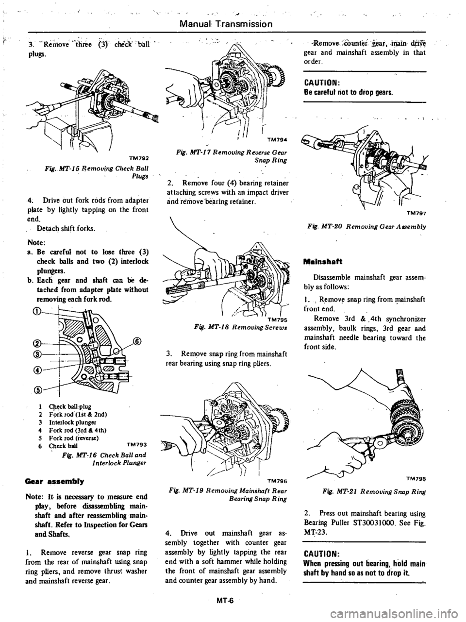
TM792
Fig
MT
15
Removing
Check
Ball
Plug
4
Drive
out
fork
rods
from
adapter
plate
by
lightly
tapping
on
the
front
end
Detach
shift
forks
Note
a
Be
careful
not
to
lose
three
3
check
balls
and
two
2
interlock
pluDgl
rs
b
Each
gear
and
sbaft
can
be
de
tached
from
adapter
plate
without
removing
each
fork
rod
D
t
@
@
6
@
1
q
eck
ball
ptug
2
Fork
Tod
1st
2nd
3
InterJock
plunger
4
Fork
rod
3rd
4th
5
Fork
rod
reverse
6
Check
ball
TM793
Fig
MT
16
Check
Ball
and
Interlock
Plunger
Gear
assembly
Note
It
is
necessary
to
measure
end
play
before
disassembling
main
sbaft
and
after
reassembling
main
shaft
Refer
to
Inspection
for
Gears
and
Shafts
1
Remove
reverse
gear
snap
ring
from
the
rear
of
mainshaft
using
snap
ring
pliers
and
remove
thrust
washer
and
mainshaft
reverse
gear
Manual
Transmission
TM794
Fig
MT
17
R
molJing
Reuerse
Gear
SfUJpRing
2
Remove
four
4
bearing
retainer
attaching
screws
with
an
impact
driver
and
remove
bearing
retainer
TM79S
Fif
MT
18
RemouingBcrews
3
Remove
snap
ring
from
mainshaft
rear
bearing
using
snap
ring
pliers
TM796
Fig
MT
19
Removing
Mainshaft
Rear
Bearing
Snap
Ring
4
Drive
out
mainshaft
gear
as
sembly
together
with
counter
gear
assembly
by
lightly
tapping
the
rea
end
with
a
soft
hammer
while
holding
the
front
of
mainshaft
gear
assembly
and
counter
gear
assembly
by
hand
MT
6
Remove
counter
g
ar
main
dfN
gear
and
mainshaft
assembly
in
that
order
CAUTION
Be
careful
not
to
drop
gears
TM797
Fig
MT
20
Removing
Gear
AlSembly
Malnshaft
Disassemble
mainsltaft
gear
assem
bly
as
follows
1
R
emove
snap
ring
from
l
l
Iinshaft
front
end
Remove
3rd
4th
synchronizer
assembly
baulk
rings
3r
gear
and
mainshaft
needle
bearing
toward
the
front
side
Fig
MT
21
Removing
Snap
Ring
2
Press
out
mainsltaft
bearing
using
Bearing
Puller
ST3003Iooo
See
Fig
MT
23
CAUTION
When
pressing
out
bearing
hold
main
shaft
by
hand
so
as
not
to
drop
it
Page 225 of 548
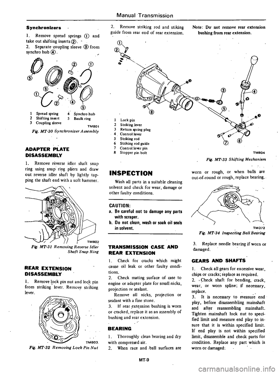
Synchronizers
I
Remove
spread
springs
j
and
take
out
shifting
inserts@
2
Separate
coupling
sleeve
@
from
synchro
hub
@
0
t
j
@
O
LJ
J
1
ID
4
Synchro
hub
S
Baulk
ring
1
Spread
spring
2
Shifting
insert
3
Coupling
sleeve
TMSOl
Fig
MT
30
Synchronjzer
Assembly
ADAPTER
PLATE
DISASSEMBLY
1
Remove
reverse
idler
shaft
snap
ring
using
snap
ri
1g
pliers
and
draw
out
reverse
idler
shaft
by
lightly
tap
ping
the
shaft
end
with
a
soft
hammer
k
Fig
MT
31
Removing
Reverse
Idler
Shaft
Snap
Ring
REAR
EXTENSION
DISASSEMBLY
I
Remove
lock
pin
nut
and
lock
pin
from
striking
1
lever
Remov
str
iking
lever
TM803
Fig
MT
32
Removing
Lock
Pin
Nut
Manual
Transmission
2
Remove
striking
rod
and
stiking
guide
from
rear
end
of
rear
extension
j
1
Lock
pin
2
Striking
lever
3
Return
spring
plug
4
Con
trollevcr
5
Striking
rod
6
Striking
fod
guide
7
Control
Ie
o
eI
pin
8
Stopper
pin
bolt
INSPECTION
Wash
all
parts
in
a
suitable
cleaning
solvent
and
check
for
wear
damage
or
other
faulty
conditions
CAUTION
a
Be
careful
not
to
damage
any
parts
with
scraper
b
Do
not
clean
wash
or
soak
oil
seals
in
solvent
TRANSMISSION
CASE
AND
REAR
EXTENSION
I
Check
for
cracks
which
might
cause
oil
leak
or
other
faulty
condi
tions
2
Check
mating
surface
of
case
to
engine
or
adapter
plate
for
small
nicks
projection
or
sealant
Remove
all
nicks
projection
or
sealant
with
a
fine
stone
3
If
rear
ext
nsion
bushing
is
worn
or
cracked
replace
it
as
an
assembly
of
bushing
and
rear
extension
BEARING
Thoroughly
clean
bearing
and
dry
with
compressed
air
2
When
race
and
ball
surfaces
are
MT
9
Note
Do
not
remove
rear
extension
bushing
from
rear
extension
@
TM804
Fig
MT
33
Shifting
Mechanism
worn
or
rough
or
when
balls
are
out
of
round
or
rough
replace
bearing
TM372
Fig
MT
34
In
pecting
Ball
Bearing
3
Replace
needle
bearing
if
worn
or
damaged
GEARS
AND
SHAFTS
I
Check
all
gears
for
excessive
wear
chips
or
cracks
replace
as
required
2
Check
shaft
for
bending
crack
wear
or
worn
spline
if
necessary
replace
3
It
is
necessary
to
measure
end
play
before
disassembling
mainshaft
and
after
reassembling
rnainshaft
Tighten
mainshaft
lock
nut
to
speci
fied
limit
and
measure
end
play
to
in
sure
that
it
is
within
specified
limit
If
end
play
is
not
within
specified
limit
disassemble
and
check
parts
for
condition
Replace
any
part
which
is
worn
or
damaged
Page 227 of 548
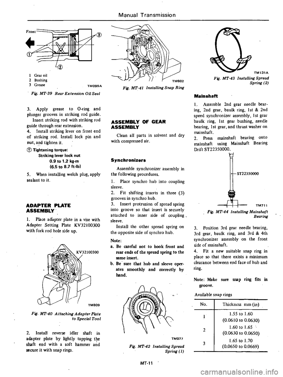
Front
if
r@
t
1
1
Gear
oil
2
Bushing
3
Grease
TM099A
Fig
MT
39
Rear
Extension
Oil
Seal
3
Apply
grease
to
D
ring
and
plunger
grooves
in
striking
rod
guide
Insert
striking
rod
with
striking
rod
guide
through
rear
extension
4
Install
striking
lever
on
front
end
of
striking
rod
Install
lock
pin
and
nut
and
tighten
it
fl
Tightening
torque
Striking
lever
lock
nut
0
9
to
1
2
kg
m
16
5
to
8
7
ft
Ib
5
When
installing
welch
plug
apply
sealant
to
it
ADAPTER
PLATE
ASSEMBLY
1
Place
adapter
plate
in
a
vise
with
Adaptet
Selling
Plate
KV32100300
with
fork
rod
hole
side
up
TMB09
Fig
MT
40
Attaching
Adapter
Phlte
to
Special
Tool
2
Install
reverse
idler
shaft
in
adapter
plate
by
lightly
tapping
the
shaft
end
with
a
soft
hammer
a
d
secure
it
with
snap
rings
Manual
Transmission
Fig
MT
4J
Installing
Snap
Ring
ASSEMBLY
OF
GEAR
ASSEMBLY
Clean
all
parts
in
solvent
and
dry
with
compressed
air
Synchronizers
Assemble
synchronizer
assembly
in
the
following
procedures
Place
synchro
hub
into
coupling
sleeve
2
Fit
shifting
inserts
in
three
3
grooves
in
synchro
hub
3
Insert
protrusion
of
spread
spring
into
groove
so
that
insert
is
securely
attached
to
inner
side
of
coupling
sleeve
Install
the
other
spread
spring
on
the
opposite
side
of
synchro
hub
Note
e
Be
careful
not
to
hook
front
and
rear
ends
of
the
spread
spring
to
the
same
insert
b
Be
sure
that
hub
and
sleeve
oper
ates
smoothly
and
correctly
by
hand
TM017
Fig
MT
42
Installing
Spread
Spring
MT
11
TM131A
Fig
MT
43
Installing
Spread
Spring
2
Mainshaft
Assemble
2nd
gear
needle
bear
ing
2nd
gear
baulk
ting
1
st
2nd
speed
synchronizer
assembly
I
st
gear
baulk
ring
1st
gear
bushing
needle
bearing
1st
gear
and
thrust
washer
on
mainshaft
2
Press
mainshaft
bearing
onto
mainshaft
using
Mainshaft
Bearing
Drift
ST22350000
H
ST22350000
TM711
Fig
MT
44
Installing
Mainshaft
Bearing
3
Position
3rd
gear
needle
bearing
3rd
gear
baulk
ring
and
3rd
4th
synchronizer
assembly
on
the
front
side
of
mainshaft
4
Fit
a
new
suitable
snap
ring
in
place
so
that
there
exists
a
minimum
clearance
between
end
face
of
hub
and
ring
Note
Make
sure
snap
ring
fits
in
groove
Available
snap
rings
No
Thickness
mm
in
1
55
to
1
60
0
0610
to
0
0630
1
60
to
1
65
0
0630
to
0
0650
1
65
to
I
70
0
0650
to
0
0669
1
2
3
Page 229 of 548
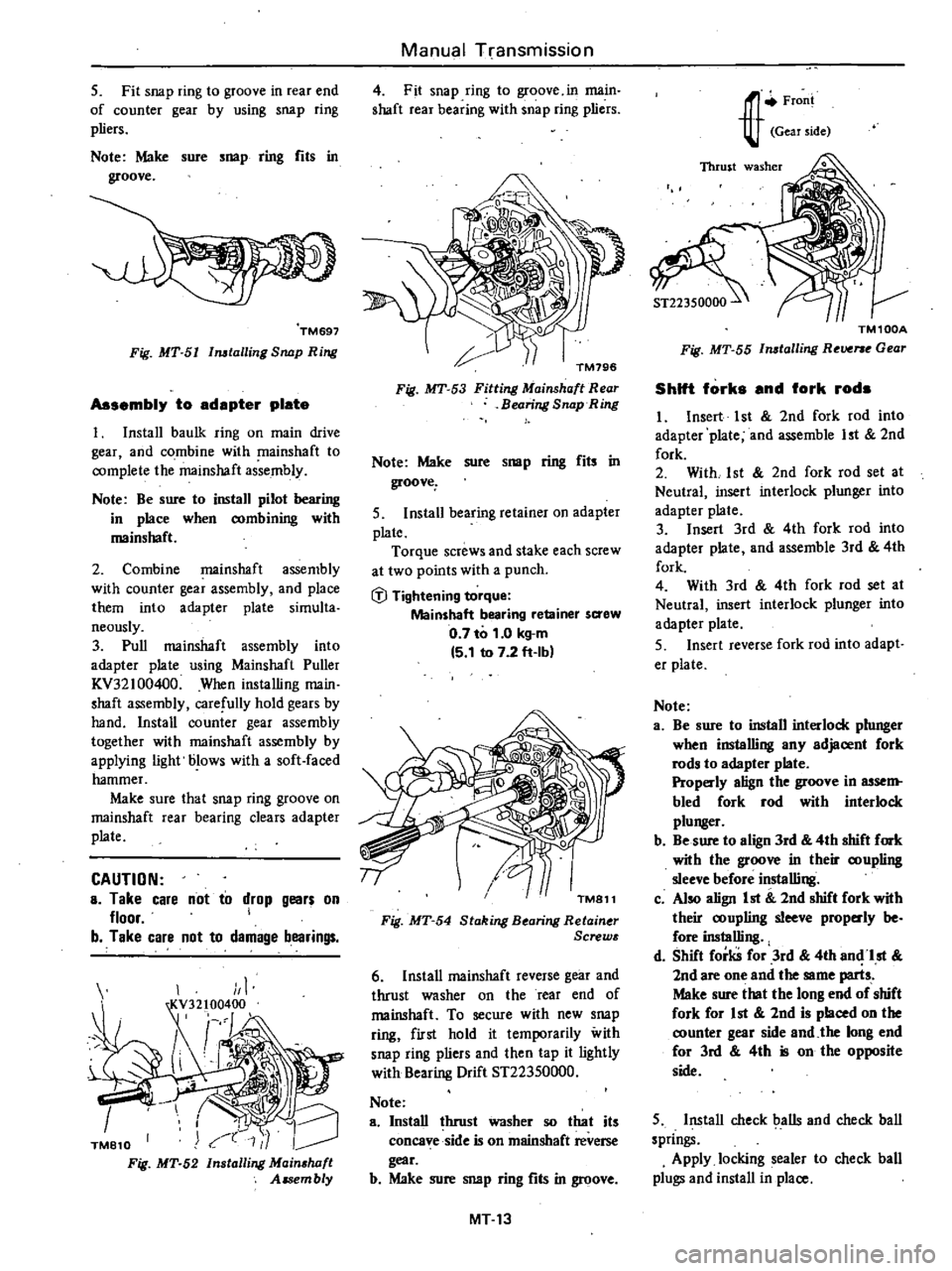
5
Fit
snap
ring
to
groove
in
rear
end
of
counter
gear
by
using
snap
ring
pliers
Note
Maire
sure
snap
ring
fits
in
groove
TM697
Fig
MT
5I
Imtalling
Snap
Ring
Assembly
to
adapter
plate
t
Install
baulk
ring
on
main
drive
gear
and
combine
with
mainshaft
to
complete
the
mainshaft
assembly
Note
Be
sure
to
install
pilot
bearing
in
place
when
combining
with
mainshaft
2
Combine
mainshaft
assembly
with
counter
gear
assembly
and
place
them
into
adapter
plate
simulta
neously
3
Pull
mainshaft
assembly
into
adapter
plate
using
Mainshaft
Puller
KV32
100400
When
installing
main
shaft
assembly
carefully
hold
gears
by
hand
Install
counter
gear
assembly
together
with
mainshaft
assembly
by
applying
light
blows
with
a
soft
faced
hammer
Make
sure
that
snap
ring
groove
on
mainshaft
rear
bearing
clears
adapter
plate
CAUTION
a
Take
care
not
to
drop
gears
on
floor
I
b
Take
care
not
to
damage
bearings
TM810
Fig
MT
52
1
Installing
Mainshaft
Assembly
Manual
Transmission
4
Fit
snap
ring
to
groove
in
main
shaft
rear
bearing
with
snap
ring
pliers
TM796
Fig
MT
53
Fitting
Mainshaft
Rear
Bearing
Snap
Ring
Note
Make
sure
snap
ring
fils
in
groove
5
Install
bearing
retainer
on
adapter
plate
Torque
screws
and
stake
each
screw
at
two
points
with
a
punch
fj
Tightening
torque
Mainshaft
bearing
retainer
saew
0
7
to
1
0
kg
m
15
1
to
7
2
ft
Ibl
TM811
Fig
MT
54
Staking
B
aring
Retain
r
Screw
6
Install
mainshaft
reverse
gear
and
thrust
washer
on
the
rear
end
of
mainshaft
To
secure
with
new
snap
ring
first
hold
it
temporarily
with
snap
ring
pliers
and
then
tap
it
lightly
with
Bearing
Drift
ST22350000
Note
a
Install
lhrust
washer
so
that
its
concave
side
is
on
mainshaet
reverse
gear
b
Make
sure
snap
ring
fits
in
groove
MT
13
J
r
Froni
Gear
side
TM100A
Fig
MT
55
Imtalling
R
Vf
e
Gear
Shift
forks
and
fork
rods
I
Insert
1st
2nd
fork
rod
into
adapter
plate
and
assemble
1st
2nd
fork
2
With
1st
2nd
fork
rod
set
at
Neutral
insert
interlock
plunger
into
adapter
plate
3
Insert
3rd
4th
fork
rod
into
adapter
plate
and
assemble
3rd
4th
fork
4
With
3rd
4th
fork
rod
set
at
Neutral
insert
interlock
plunger
into
adapter
plate
S
Insert
reverse
fork
rod
into
adapt
er
plate
Nole
a
Be
sure
to
install
interlock
plunger
when
installing
any
adjacent
fork
rods
to
adapter
plate
Properly
align
the
groove
in
assem
bled
fork
rod
with
interlock
plunger
b
Be
sure
to
align
3rd
4th
shift
fork
wilh
the
groove
in
their
coupling
sleeve
before
installing
c
Also
align
1st
2nd
shift
fork
with
their
coupling
sleeve
prop
dy
be
fore
inslalling
d
Shift
forks
for
3rd
4th
an
1st
2nd
are
one
and
the
same
parts
Make
sure
that
the
long
end
of
shift
fork
for
1st
2nd
is
placed
on
the
counter
gear
side
and
the
long
end
for
3rd
4th
is
on
the
opposite
side
5
Install
check
balls
and
check
ball
springs
Apply
locking
sealer
to
check
ball
plugs
and
install
in
place
Page 230 of 548
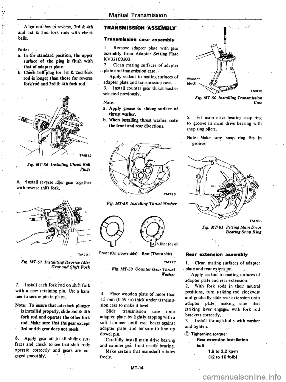
Align
notches
in
reverse
3rd
4th
and
1st
2nd
fork
rods
with
check
balls
Note
a
In
the
standard
position
the
upper
surface
of
the
ping
is
nush
with
thaI
of
adapter
plate
b
CheCk
balfpIug
for
i
st
2nd
fork
rod
is
longer
than
those
for
reverse
forkrod
and
3rd
4th
fork
rod
Manual
Transmission
TRANS
SSION
ASSEMBLY
Transmission
case
assembly
Remove
adapter
plale
with
gear
assembly
from
Adapter
Setting
Plate
KV32100300
2
Clean
mating
surfaces
of
adapter
plate
and
transmission
case
Apply
sealant
to
mating
surfaces
of
adapter
plate
3
nd
transmission
case
3
Install
counter
gear
thrust
washer
selected
previously
Note
a
Apply
grease
to
stiding
sorface
of
thrust
washer
b
When
installing
thrust
washer
note
the
front
and
rear
directions
Fig
MT
56
Installing
Check
Ball
0
Plugs
6
1nstall
rev
rse
idler
gear
together
with
reverse
shift
fork
TM791
Fig
MT
57
Installting
Re
ldler
Getg
and
Shift
Fork
7
Install
each
fork
rod
on
shift
fork
with
new
retainif
g
pin
U
a
ham
mer
toseCUfe
pin
in
place
Note
To
insure
that
interlock
plunger
is
installed
properly
slide
3rd
4th
fork
rod
and
operate
the
other
fork
rod
Make
sure
that
the
gear
except
lrd
or
4th
gear
does
not
mesh
8
Apply
g
ar
oil
o
all
sliding
sur
faces
and
check
to
see
that
shift
rods
operate
correctly
and
gears
are
en
gaged
smoothly
Fig
MT
58
Installing
Thrust
Washer
Front
Oil
groove
side
Rear
Thrust
side
TM727
Fig
MT
59
Counter
Gear
Thru
t
Washt
r
4
Place
wooden
plate
of
more
than
15
mm
0
59
in
thick
under
transmis
sion
case
to
make
it
level
Slide
transmission
case
onto
adapter
plate
by
lightly
tapping
with
a
soft
hammer
until
case
bears
against
adapter
plate
and
be
sure
to
line
up
dowel
pin
Carefully
install
main
drive
bearing
and
counter
gear
front
needle
bearing
Make
certain
that
rnainshaft
rotates
freely
MT14
1
Wooden
block
TM813
Fig
MT
60
Installing
Transmiuion
Cale
5
Fit
main
drive
bearing
snap
ring
to
groove
in
main
drive
bearing
with
snap
ring
pliers
Note
Make
sure
snap
ring
fits
in
groove
Fig
MT
61
Fitting
Main
Dri
Bearing
Snap
Ring
Rear
extension
assembly
Clean
mating
surfaces
of
adapter
p
Iat
aIld
rear
e
tens
i91
Apply
sealant
to
mating
surfaces
of
adapter
plate
and
rear
extension
2
With
fork
rods
in
their
neutral
positions
turn
striking
rod
clockwise
and
gradually
slide
rear
extension
onto
adapter
plate
making
sure
that
striking
lever
engages
with
fork
rod
brackets
correctly
3
Install
through
bolts
with
washer
and
tighten
b
Tightening
torque
Rear
extension
installation
bolt
1
6
to
2
2
kg
m
12
to
16
ft
lb