engine DATSUN PICK-UP 1977 Service Manual
[x] Cancel search | Manufacturer: DATSUN, Model Year: 1977, Model line: PICK-UP, Model: DATSUN PICK-UP 1977Pages: 537, PDF Size: 35.48 MB
Page 122 of 537
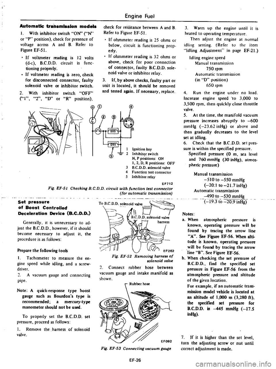
AUtomatic
trailamlsalon
modela
I
With
inhibitor
switch
ON
UN
or
P
position
check
for
presence
of
voltage
across
A
and
B
Refer
to
Figure
EF
51
If
voltmeter
ading
is
12
volts
d
c
B
C
D
O
circuit
is
func
tioning
properly
If
vol
tmeter
ading
is
zero
check
for
disconnected
connector
faulty
solenoid
valve
m
inhibitor
switch
2
With
inhibitor
switch
OFF
HI
2
IY
or
oR
position
Engine
Fuel
check
for
resistance
between
A
and
B
Refer
to
Figure
EF
51
If
ohmmeter
reading
is
25
ohms
or
below
circuit
is
functioning
prop
erly
If
ohmmeter
reading
is
32
ohms
or
above
check
for
poor
connection
of
connec
or
faulty
B
C
D
D
sole
noid
valve
or
inhibitor
relay
3
If
by
above
checks
faulty
part
or
unit
is
located
it
should
be
moved
and
tested
again
If
necessary
replace
yu
@
@
1
Ignition
key
2
Inhibit
T
switch
N
P
positions
ON
I
2
D
R
positions
OFF
3
D
C
D
D
solenoid
valve
4
Function
test
connector
5
Inhibitor
relay
EF712
Fig
EF
51
Checking
B
C
D
D
circuit
with
unction
t
st
connector
for
automatic
transmi
sion
Set
pressure
of
Boost
Controlled
Deceleration
Device
B
C
D
O
Generally
it
is
unnecessary
to
ad
just
the
B
CD
D
however
if
it
should
become
necessary
to
adjust
it
the
procedure
is
3S
follows
Prepare
the
foUowing
tool
I
Tachometer
to
measure
the
en
gine
speed
while
idling
and
a
screw
driver
2
A
vacuum
gauge
and
connecting
pipe
Note
A
quick
response
type
hoost
gauge
such
as
Bourdon
s
type
is
recommended
a
mercury
type
manometer
should
not
be
used
To
properly
set
the
B
C
D
D
set
pressure
proceed
as
follows
I
Remove
the
harness
of
solenoid
valve
To
B
D
D
solenoid
valve
1
B
C
D
D
olenoid
valve
harness
EF262
Fig
EF
52
Removing
harness
of
solenoid
valve
2
Connect
rubber
hose
between
vacuum
gauge
and
intake
manifold
as
shown
Fig
EF
53
Connecting
vacuum
gauge
EF
26
3
Warm
up
the
engine
until
it
is
heated
to
operating
temperature
Then
adjust
the
engine
at
nunnal
idling
setting
Refer
to
the
item
Idling
Adjustmenl
in
page
EF
21
Idling
engine
speed
Manual
transmission
750
rpm
Automatic
transmission
in
D
position
650
rpm
4
Run
the
engine
under
no
load
Increase
engine
speed
to
3
000
to
3
500
rpm
then
quickly
close
throttle
valve
5
At
the
time
the
manifold
vacuum
p
ssure
increases
abruptly
to
600
mmHg
23
62
inHg
or
above
and
then
graduaUy
decreases
to
the
level
set
at
idling
6
Check
that
the
B
C
D
D
set
pres
sure
is
within
the
specified
pressure
Specified
pressure
0
m
sea
level
and
760
mmHg
30
inHg
atmos
pheric
pressu
Manual
transmission
510
to
550
mmHg
20
1
to
21
7
inHg
Automatic
transmission
490
to
530
mmHg
19Tto
20
9
inHg
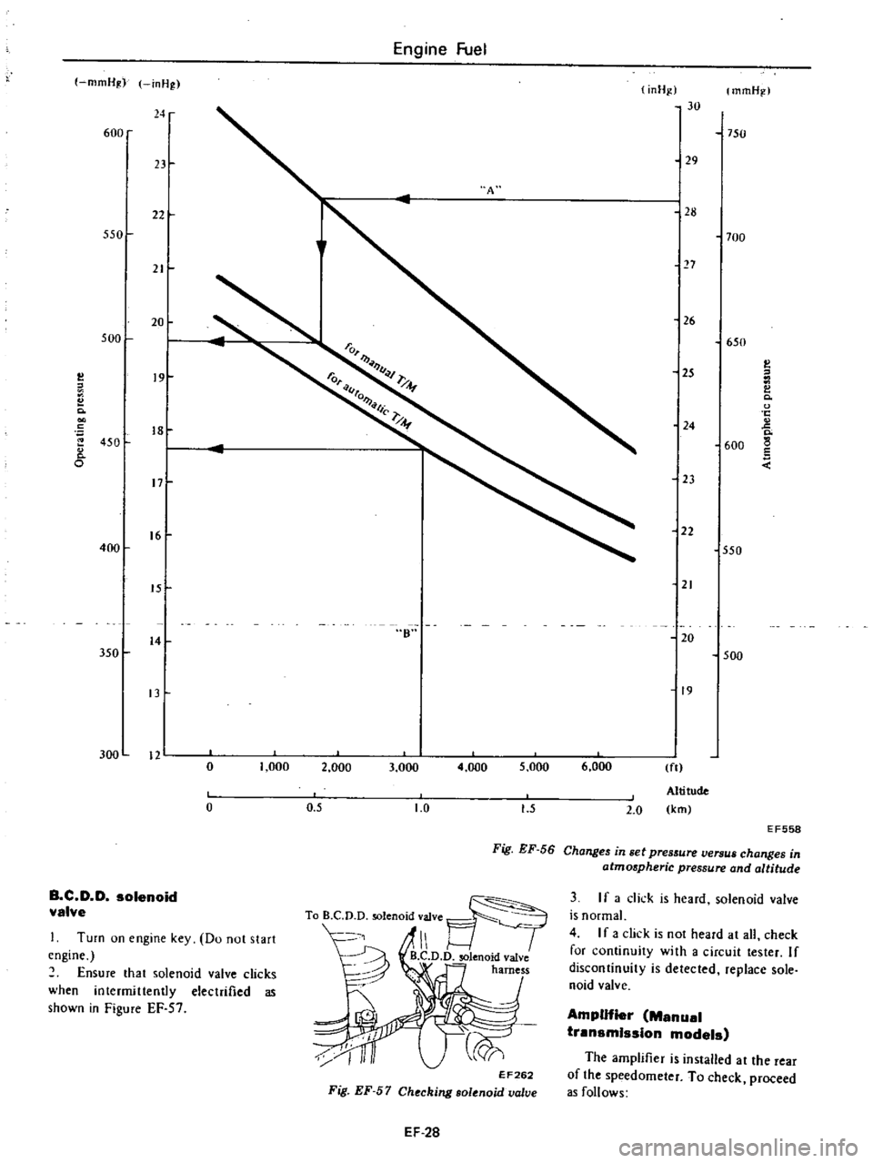
Notes
a
When
atmospheric
pressure
is
known
operating
pressure
will
be
found
by
tracing
the
arrow
line
A
See
Figure
EF
56
When
alti
tude
is
known
operating
pressure
will
be
found
by
tracing
the
arrow
line
B
See
Figu
EF
56
b
When
checking
the
set
pressu
of
B
CD
D
find
the
specified
set
pressu
in
Figure
EF
56
from
the
atmospheric
pressure
and
altitude
of
the
given
location
For
example
if
an
automatic
trans
mission
model
vehicle
is
located
at
an
altitude
of
1
000
m
3
280
ft
the
specified
set
p
ssu
for
B
C
D
D
is
445
mmHg
17
5
inHg
7
If
it
is
higher
than
the
set
level
turn
the
adjusting
screw
or
nut
until
correct
adjustment
is
made
Page 123 of 537
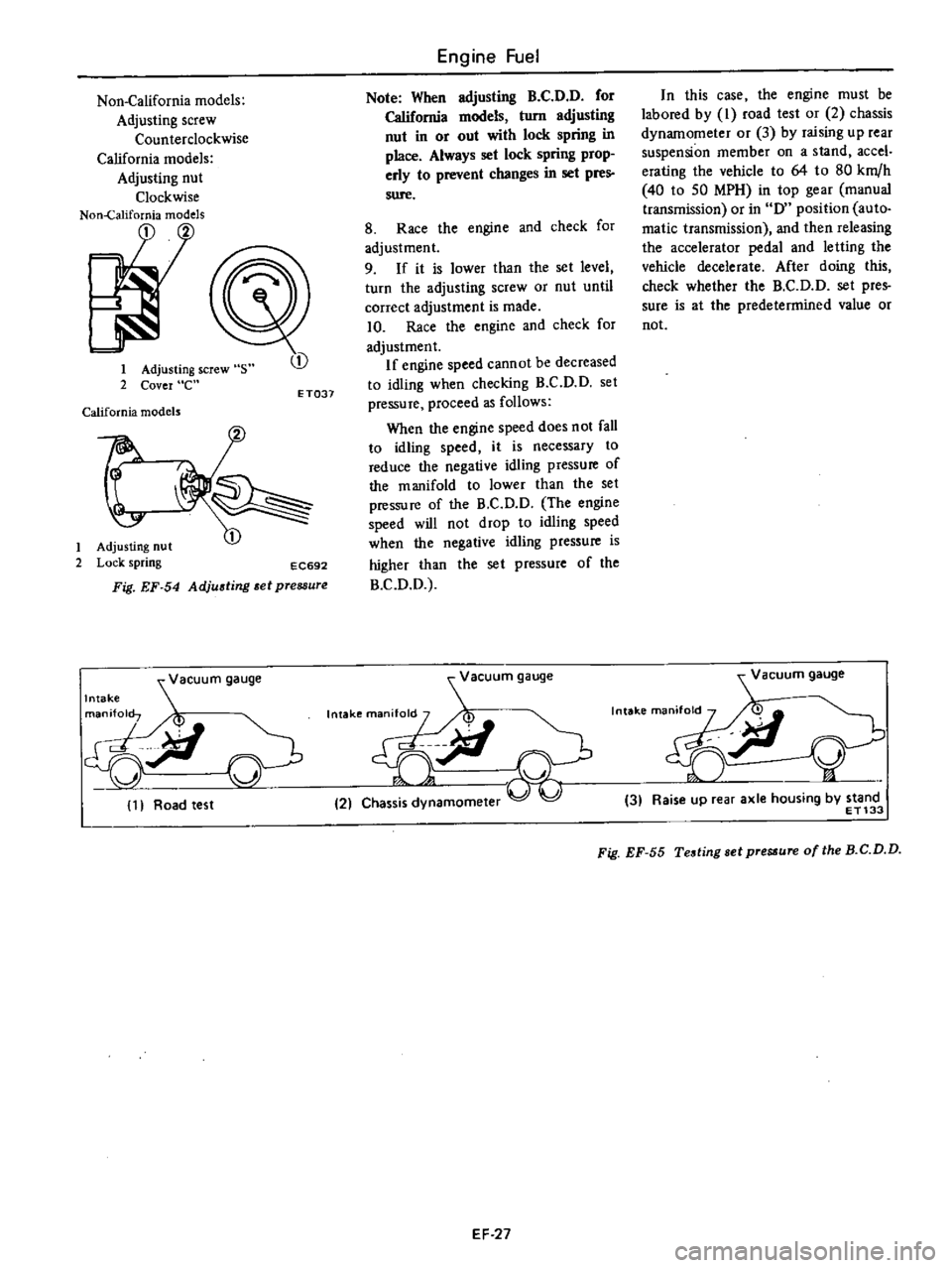
Non
California
models
Adjusting
screw
Counterclockwise
California
models
Adjusting
nut
Clockwise
Non
California
models
1
2
1
Adjusting
screw
s
2
Cover
e
California
models
t
1
Adjusting
nut
2
Lock
spring
EC692
Fig
EF
54
Adjusting
et
pressure
vacuum
gauge
Intake
gjl
11
Road
test
CD
ET037
Engine
Fuel
Note
When
adjusting
B
C
D
D
for
California
models
turn
adjusting
nut
in
or
out
with
lock
spring
in
place
Always
set
lock
spring
prop
erly
to
prevent
changes
in
set
pres
sure
8
Race
the
engine
and
check
for
adjustment
9
If
it
is
lower
than
the
set
level
turn
the
adjusting
screw
or
nut
until
correct
adjustment
is
made
10
Race
the
engine
and
check
for
adjustment
If
engine
speed
cannot
be
decreased
to
idling
when
checking
B
C
D
D
set
pressure
proceed
as
follows
When
the
engine
speed
does
not
fall
to
idling
speed
it
is
necessary
to
reduce
the
negative
idling
pressure
of
the
manifold
to
lower
than
the
set
pressure
of
the
B
C
D
O
The
engine
speed
will
not
drop
to
idling
speed
when
the
negative
idling
pressure
is
higher
Ihan
the
sel
pressure
of
the
B
C
O
O
acuum
gauge
Intakema
M
V
9iI
21
Chas
amomeler
In
this
case
the
engine
must
be
labored
by
I
road
test
or
2
chassis
dynamometer
or
3
by
raising
up
rear
suspension
member
on
a
stand
accel
erating
the
vehicle
to
64
to
80
km
h
40
10
50
MPH
in
top
gear
manual
transmission
or
in
0
position
auto
matic
transmission
and
then
releasing
the
accelerator
pedal
and
letting
the
vehicle
decelerate
After
doing
this
check
whether
the
B
C
O
D
set
pres
sure
is
at
the
predetermined
value
or
not
Vacuum
gauge
n
i
Y
3
Raise
up
rear
axle
housing
by
stand
ET133
Fig
EF
55
Testing
sel
pre
ure
of
the
B
C
D
D
EF
27
Page 124 of 537
300
n
o
o
B
C
D
D
solenoid
valve
I
Turn
on
engine
key
Do
not
start
engine
Ensure
that
solenoid
valve
clicks
when
intermittently
electrified
as
shown
in
Figure
EF
57
1
000
2
000
3
000
4
000
5
000
0
5
1
0
6
000
ft
Altitude
km
1
5
2
0
EF558
Fig
EF
56
Changes
in
set
pres
ure
versus
changes
in
atmospheric
pressure
and
altitude
EF262
Fig
EF
57
Checking
solenoid
valve
EF
28
3
If
a
dick
is
heard
solenoid
valve
is
normal
4
I
f
a
dick
is
not
heard
ar
all
check
for
continuity
with
a
circuit
tester
If
discontinuity
is
detected
replace
sole
noid
valve
Amplifier
Manual
transmIssIon
models
The
amplifier
is
installed
at
the
rear
of
the
speedometer
To
check
proceed
as
follows
Page 125 of 537
I
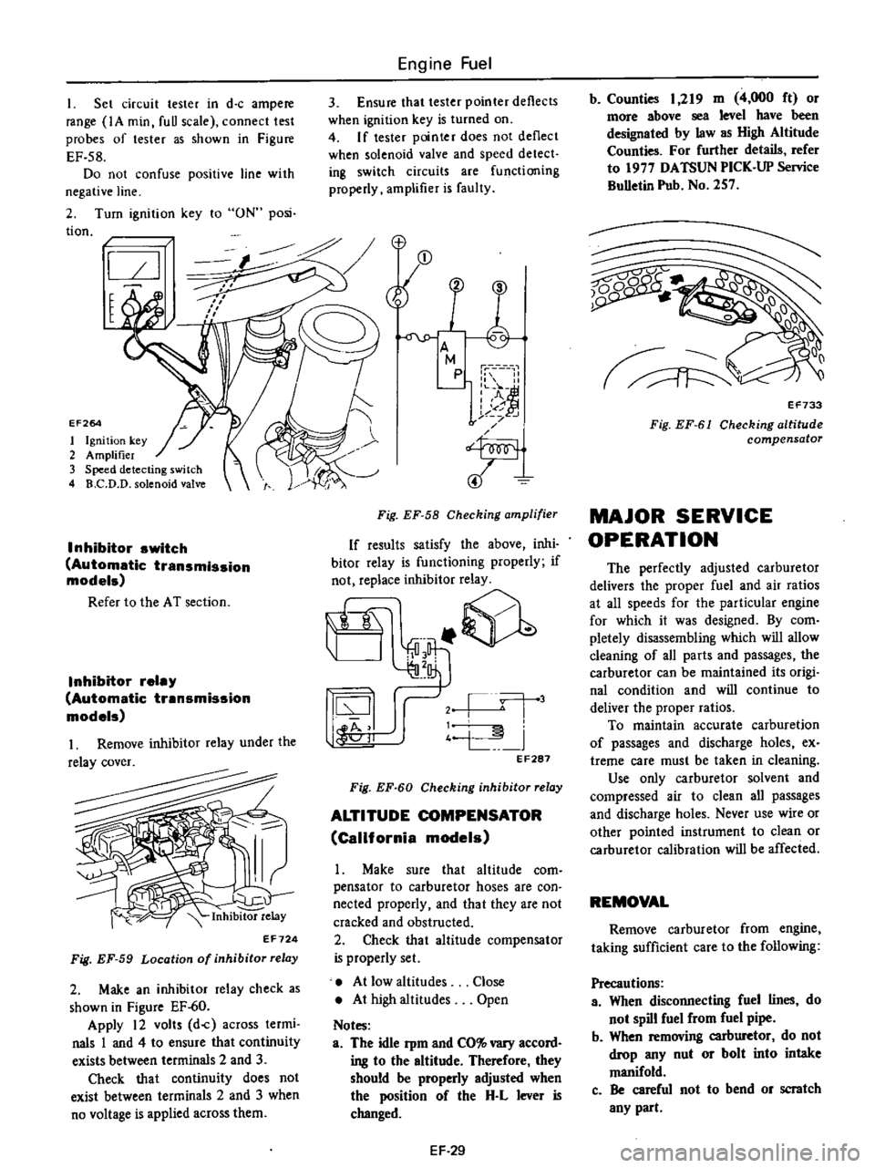
Set
circuit
tester
in
d
c
ampere
range
IA
min
fuU
scale
connect
test
probes
of
tester
as
shown
in
Figure
EF
58
Do
not
confuse
positive
line
with
negative
line
2
Turn
ignition
key
to
ON
posi
tion
I
t
EF264
1
Ignition
key
2
Amplifier
3
Speed
detecting
switch
4
B
C
D
D
solenoid
valve
Inhibitor
switch
Automatic
transmission
models
Refer
to
the
AT
section
Inhibitor
relay
Automatic
transmission
models
Inhibitor
relay
EF724
Fig
EF
59
Location
of
inhibitor
relay
2
Make
an
inhibitor
relay
check
as
shown
in
Figure
EF
60
Apply
12
volts
d
c
across
termi
nals
1
and
4
to
ensure
that
continuity
exists
between
terminals
2
and
3
Check
that
continuity
does
not
exist
between
terminals
2
and
3
when
no
voltage
is
applied
across
them
Engine
Fuel
3
Ensure
that
tester
pointer
deflects
when
ignition
key
is
turned
on
4
If
tester
pointer
does
not
deflect
when
solenoid
valve
and
speed
detect
ing
switch
circuits
are
functioning
properly
amplifier
is
faulty
Fig
EF
58
Checking
amplifier
If
results
satisfy
the
above
inhi
bitor
relay
is
functioning
properly
if
not
replace
inhibitor
relay
it
@
j
l
j
4
L
I
44
11
oJ
EF287
Fig
EF
60
Checking
inhibitor
relay
ALTITUDE
COMPENSATOR
California
models
Make
sure
that
altitude
com
pensator
to
carburetor
hoses
are
con
nected
properly
and
that
they
are
not
cracked
and
obstructed
2
Check
that
altitude
compensator
is
properly
set
At
low
altitudes
At
high
altitudes
Notes
a
The
idle
Pm
and
CO
vary
accord
ing
to
the
altitude
Therefore
they
should
be
properly
adjusted
when
the
position
of
the
H
L
lever
is
changed
Close
Open
EF
29
b
Counties
1
219
m
4
000
ft
or
more
above
sea
level
have
been
designated
by
law
as
High
Altitude
Counties
For
further
details
refer
to
1977
DATSUN
PICK
UP
Service
BuUetin
Pub
No
257
Q0
1
v
EF733
Fig
EF
61
Checking
altitude
compensator
MAJOR
SERVICE
OPERATION
The
perfectly
adjusted
carburetor
delivers
the
proper
fuel
and
air
ratios
at
all
speeds
for
the
particular
engine
for
which
it
was
designed
By
com
pletely
disassembling
which
will
allow
deaning
of
all
parts
and
passages
the
carburetor
can
be
maintained
its
origi
nal
condition
and
will
continue
to
deliver
the
proper
ratios
To
maintain
accurate
carburetion
of
passages
and
discharge
holes
ex
treme
care
must
be
taken
in
cleaning
Use
only
carburetor
solvent
and
compressed
air
to
clean
all
passages
and
discharge
holes
Never
use
wire
or
other
pointed
instrument
to
clean
or
carburetor
calibration
will
be
affected
REMOVAL
Remove
carburetor
from
engine
taking
sufficient
care
to
the
following
Precautions
a
When
disconnecting
fuel
lines
do
not
spill
fuel
from
fuel
pipe
b
When
removing
carburetor
do
not
drop
any
nut
or
bolt
into
intake
manifold
c
Be
careful
not
to
bend
or
scratch
any
part
Page 126 of 537
Engine
Fuel
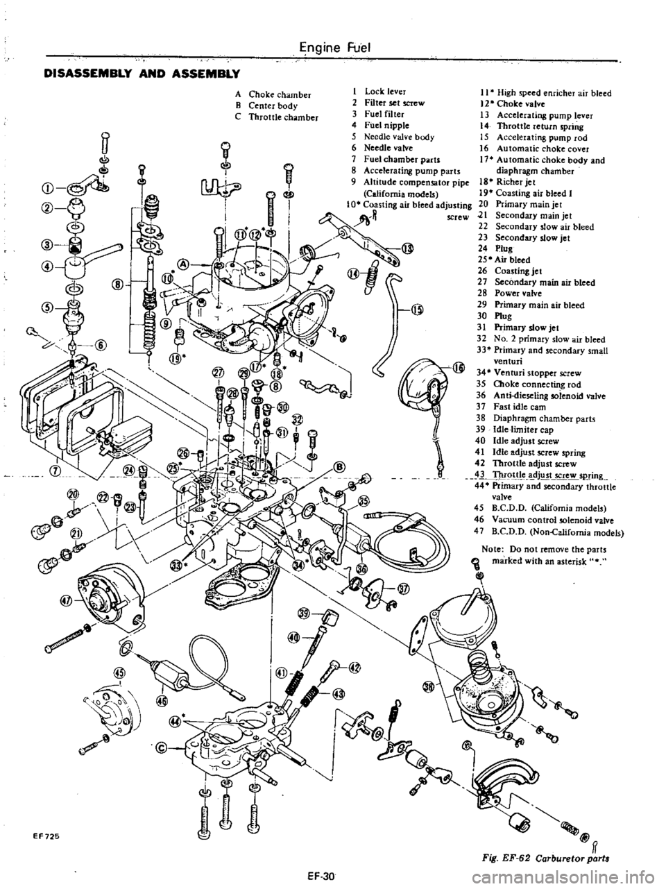
DISASSEMBLY
AND
ASSEMBLY
ff
C
oI
Q
f
@
ID
J
@
tJ
@
1
Lock
lever
2
Filter
set
screw
3
Fuel
filter
4
Fuel
nipple
5
Needle
valve
body
6
Needle
valve
7
Fuel
chamber
parts
8
Accelerating
pump
parts
9
Altitude
compensator
pipe
California
models
tng
ail
bleed
adJ
@
@1
@
A
Choke
chamber
B
Center
body
C
Throttle
chamber
I
J
@
EF725
EF30
11
High
speed
enricher
air
bleed
12
Choke
valve
13
Accelerating
pump
lever
14
Throttle
return
spring
15
Accelerating
pump
rod
16
Automatic
choke
cover
17
Automatic
choke
body
and
diaphragm
chamber
18
Richer
jet
19
Coasting
air
bleed
I
20
Primary
main
jet
21
Secondary
main
jet
22
Secondary
slow
air
bleed
23
Secondary
slow
jet
24
Plug
25
Air
bleed
26
Coasting
jet
27
Secondary
main
air
bleed
28
Power
valve
29
Primary
main
air
bleed
30
Plug
31
Primary
slow
jet
32
No
2
primary
slow
air
bleed
33
Primary
and
secondary
small
venturi
34
Venturi
stopper
screw
35
Choke
connecting
rod
36
Anti
dieseling
solenoid
valve
37
Fast
idle
cam
38
Diaphragm
chamber
parts
39
Idle
limiter
cap
40
Idle
adjust
screw
41
Idle
adjust
screw
spring
42
Throttle
adjust
screw
3
Thr9ttle
dj
t
5Crew
spring
44
Primary
and
secondary
throttle
valve
45
B
C
D
D
California
models
46
Vacuum
control
solenoid
valve
47
B
C
D
D
Non
Califomia
models
Note
Do
not
remove
the
parts
marked
with
an
asterisk
Ill
@ff
Fig
EF
62
Carburetor
part
Page 127 of 537
Engine
Fuel
Disassembly
Properly
filling
wrenches
and
screwdrivers
must
be
used
on
the
nozzles
and
jets
as
well
as
on
the
screws
and
nuts
and
care
must
be
ex
ercised
not
to
damage
any
parts
2
Clean
the
carburetor
thorougWy
beiore
disassembly
3
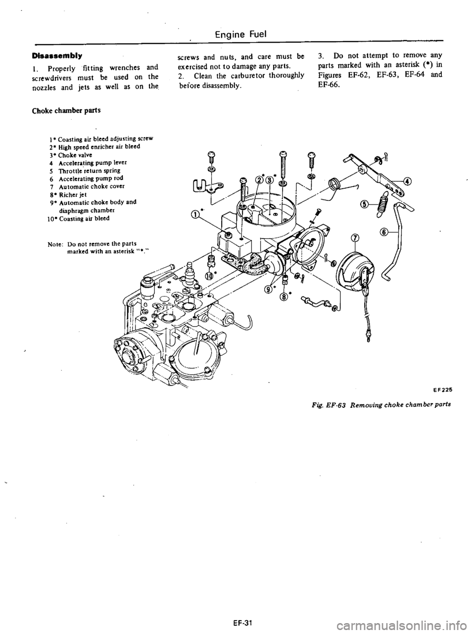
Do
not
attempt
to
remove
any
parts
marked
with
an
asterisk
CO
in
Figures
EF
62
EF
63
EF
64
and
EF
66
Choke
chamber
parts
1
Coasting
air
bleed
adjusting
screw
2
High
speed
enricher
air
bleed
3
Choke
valve
4
AcceJera
ing
pump
lever
5
Throttle
return
spring
6
Accelerating
pump
rod
7
Automatic
choke
cover
8
Richer
jet
9
Automatic
choke
body
and
diaphragm
chamber
10
Coasting
air
bleed
I
fi
1i
8
J
@
Note
Do
not
remove
the
parts
marked
with
an
asterisk
l
EF
225
Fig
EF
63
Removing
choke
chamber
parts
EF
31
Page 128 of 537
Engine
Fuel
1
l
@
Vacuum
control
solenoid
valve
2
B
C
D
D
3
Coasting
jet
4
Secondary
slow
jet
5
ptug
6
Air
bleed
1
Secondary
slow
air
bleed
8
Secondary
main
air
bleed
9
Power
valve
10
Primary
main
air
bleed
11
Weight
and
outlet
valve
12
ptug
13
Primary
slow
jet
14
Ptirnar
slow
air
bleed
15
Accelerator
pump
assembly
16
AntkUeselingsolenoid
vain
17
Fast
idle
earn
18
Chok
e
connecting
rod
19
Fast
idle
earn
shaft
20
Ventuci
stopper
screw
21
Primary
and
secondary
small
venturi
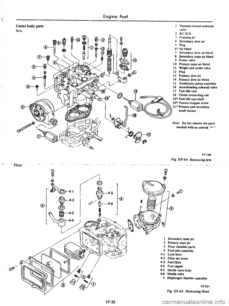
Center
body
parts
Sets
Note
Do
not
remove
the
parts
marked
with
an
asterisk
It
EF726
Fig
EF
64
Removing
jets
Float
I
i
@
i
j
1
L
4
2
V
4
S
@
c
4
6
e4
11
Qll
1D
Yr
J
1
t
t
1
lil
c
@5
1
p
u
I
r
i
r
1
CJi
U
7
to1
8rtj
lv
Ji
JlJ
if
I
1
2
3
4
4
1
4
2
4
3
44
4
5
Hi
5
Secondary
main
jet
Primary
main
jet
Float
chamber
parts
Fuel
inlet
assembly
Lock
lever
Filter
set
screw
Fuel
f1Iter
Fuel
nipple
Needle
valve
body
Needle
valve
Diaphragm
chamber
aiSembly
EF227
Fig
EF
65
Removing
float
EF
32
Page 129 of 537
Engine
Fuel
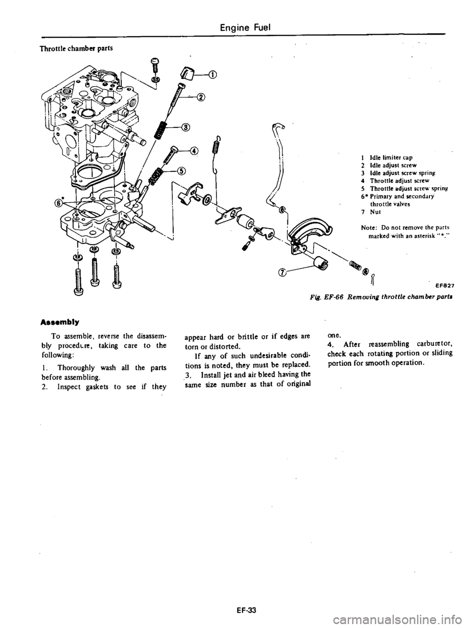
Throttle
chamber
parts
I
Idle
limiter
cap
2
Idle
adjust
screw
3
Idle
adjust
screw
sprinl
4
Throttle
adjust
screw
5
Throttle
adjust
screw
sprini
6
Primary
and
secondary
throttle
valves
7
Nut
Notc
Do
not
remove
the
parlS
marked
with
an
asterisk
@ff
EF827
Fig
EF
66
Removing
throttle
chamlHr
parta
Assembly
To
assemble
reverse
the
disassem
bly
procedcre
taking
care
to
the
following
I
Thoroughly
wash
all
the
parts
before
assembling
2
Inspect
gaskets
to
see
if
they
appear
hard
or
brittle
or
if
edges
are
torn
or
distorted
If
any
of
such
undesirable
condi
tions
is
noted
they
must
be
replaced
3
Install
jet
and
air
bleed
having
the
same
size
number
as
that
of
original
one
4
After
reassembling
carburetor
check
each
rotating
portion
or
sliding
portion
for
smooth
operation
EF
33
Page 130 of 537
CLEANING
AND
INSPECTION
Dirt
gum
wuler
or
l
arbon
con
taminatiun
in
or
on
exterior
moving
parts
of
a
arburctor
arc
often
respon
sihk
for
unsatisfactory
performance
For
this
reason
efficient
carbutetioll
dcpends
upon
careful
cleaning
and
inspection
while
servicing
I
Blow
all
passages
and
castings
with
compressed
air
and
blow
off
all
parts
until
dry
Note
Do
not
pass
drills
or
wires
through
calibrated
jet
or
passaaa
as
this
may
enlarge
orirlce
and
seriously
affect
carburetor
calibrs
lion
2
Check
all
parts
for
wear
If
wear
is
noted
damaged
parts
must
be
re
placed
Note
especially
the
following
Engine
Fuel
I
Check
float
needle
and
seat
for
wear
If
wear
is
noted
assembly
must
be
replaced
2
Check
throule
and
choke
shaft
bores
in
throtlle
chamber
and
choice
chamber
for
wear
or
out
of
roundness
3
Inspect
idle
adjusting
needle
for
burrs
or
ridges
Such
a
condition
re
quires
replacemen
1
3
Inspect
gaskets
0
see
if
they
appear
hard
or
briUle
or
if
edges
are
torn
or
distorted
If
any
such
condi
tion
i
noted
they
must
be
replaced
4
Check
filter
screen
for
dirt
or
lint
Clean
and
if
screen
is
distorted
or
remain
plugged
replace
5
Check
linkage
for
operating
condition
6
Inspect
operation
of
accelerating
pump
Pour
f
el
into
jloat
chamber
and
make
throtlle
lever
operate
Check
condition
of
fuel
injection
from
the
EF
34
accelerating
nowe
7
Push
connecting
rod
of
dia
phragm
chamber
and
block
passage
of
vacuum
with
finger
When
connecting
rod
becomes
free
check
for
leakage
of
air
or
damage
to
diaphragm
Jets
Carburetor
performance
depends
on
jet
and
air
bleed
That
is
why
these
components
must
be
fabricated
with
utmost
care
To
clean
them
use
cleaning
solvent
and
blow
air
on
them
Larger
inner
numbers
tamped
on
the
jet
indicate
larger
diameters
Ac
cordingly
main
and
slow
jets
with
lalger
nUmbers
provide
richer
mixture
the
smaller
the
numbers
the
leaner
the
mixture
Conversely
the
main
and
slow
air
bleeds
through
which
air
to
passes
through
make
the
fueLleaner
if
they
bear
larger
numbers
the
smaller
the
numbers
the
richer
the
fuel
Page 131 of 537
Engine
Fuel
SERVICE
DATA
AND
SPECIFICATIONS
Airclelllcr
Ail
control
val
partially
opem
Air
ntrol
valve
fuUy
opens
Idle
ompensatoI
partially
opens
Hi
mettiNo
l
Bi
metal
No
2
Idle
ompen
tor
fully
opens
Bi
metal
No
1
Hi
metd
No
2
Fuels
Stem
Fuel
prtuure
Fuel
pump
apacHy
C
rbu
tor
C
rbu
tor
type
Carburetor
model
Oc
oF
oCe
F
oCe
F
Oc
OF
kpJcm2
poi
US
pt
min
at
rpm
Outlet
diameter
Venturi
diameter
Main
jet
Main
air
bleed
Slow
jet
Power
val
Float
level
U
fuel
preuure
rom
in
mm
in
mm
in
kg
cm2
psi
Adjustment
Engine
idling
Ignition
timing
Idle
speed
CO
at
mloro
Fuel
level
adjustment
Gap
between
Ive
stem
and
noat
at
mm
in
H
H
h
Fast
idle
adjwtmcnt
Fast
idle
earn
tint
step
Gap
between
throttle
IYe
and
carburetor
body
mm
in
Vacuum
break
adjustment
Gap
between
choke
alve
and
carburetor
body
mm
in
Choke
unloadel
adjusttncnt
Gap
between
choke
alw
and
carburetor
body
rom
in
Bi
metalsettinl
Bi
metal
resistance
at
2Ioe
700F
n
Bi
metalsettina
lnterloc
k
opcnina
of
primary
and
secondary
throtUc
valves
mmOn
Duh
pot
adjustment
without
loadin
I
m
Anti
diclClinasolenoid
valV
C
tiahtenina
torque
ka
m
in
lb
a
c
D
D
set
p
JSure
0
m
sea
level
and
760
mmHg
30
inlla
atmospheric
pressure
J
mmHa
inHg
R
C
D
D
tiahteninl
torque
kg
m
n
b
Nl
n
California
modell
Manual
transmiSsion
I
Automatic
transmission
California
modeb
Manual
transmission
I
Automatic
transmission
30
to
54
86
to
129
above
55
131
30
to
54
86
to
129
above
55
131
60
to
70
140
to
158
70
to
90
158
to
194
60
to
70
140
to
158
70
to
90
158
to
194
above
70
158
above
90
194
above
70
158
above
90
194
0
21
to
0
27
2
99
to
3
84
t
OOO
2
i
I
OOO
0
21
to
0
27
2
99
to
3
84
1
000
2
i
I
OOO
Strombcra
type
OCH340
7A
DCH340
48A
Stromt
rg
type
DCH34Q
45B
DCH340
46A
Primary
Secondary
Primary
Secondary
Primary
Secondary
Primary
Secondary
30
I8t
340
339
30
1
181
34
1
339
30
1
181
34
1
339
30
1
181
34
1
339
24
0
945
310
220
24
0
945
31
1
220
24
0
945
31
1
220
24
0
945
31
1
220
199
1160
199
1160
1101
1160
101
1160
170
160
170
160
170
60
170
1
60
148
1100
148
1100
148
1100
148
180
143
143
140
140
23
0
906
23
0
906
23
0
906
23
0
906
0
17
2
408
0
17
2
40B
0
17
2
408
0
17
2
408
1201750
rpm
CO
2
1
120
650
rpm
0
100
750rpm
C02
t
1
120
650
rpm
0
position
CO
2
t
1
position
CO
2
t
1
7
2
0
283
7
2
0
283
7
2
0
283
7
2
0
283
23
0
906
23
0
906
23
0
906
23
0
906
1
3
to
1
7
1
3
to
1
7
1
3
to
1
7
1
3
to
1
7
0
051
to
0
067
0
051
to
0
067
0
051
to
0
067
0
051
to
0
067
1
33
to
1
47
1
58
to
1
72
1
33
to
1
47
1
58
to
1
72
0
0524
to
0
0579
0
0622
to
0
0677
0
0524
to
0
0579
0
0622
to
0
0677
1
42
0
056
1
42
0
056
1
42
0
056
1
5
0
059
2
45
0
096
2
45
0
096
2
4
0
096
2
45
0
096
3
7
to
8
9
3
7
to
8
9
3
7
to
B
9
3
7
to
8
9
Center
of
the
ndex
mark
Center
of
the
index
mark
7
38
0
291
7
38
0
291
7
38
0
290
7
38
0
291
1
900
to
2
100
1
650
to
1
850
1
900
to
2
100
1
650
to
1
850
180
to
350
156
to
304
180
to
350
156
to
304
180
to
350
156
to
304
180
to
350
156
to
304
510
to
550
490
to
530
510
to
550
490
to
530
20
1
to
21
7
19
3
to
20
9
20
1
to
21
7
19
3
to
20
9
20
to
40
17
4
to
34
1
20
to
40
11
4
to
34
7
20
to
40
17
4
to
34
7
20
to
40
17
4
to
34
1
EF
35