engine DATSUN PICK-UP 1977 Manual PDF
[x] Cancel search | Manufacturer: DATSUN, Model Year: 1977, Model line: PICK-UP, Model: DATSUN PICK-UP 1977Pages: 537, PDF Size: 35.48 MB
Page 80 of 537

Engine
Mechanical
SPECIAL
SERVICE
TOOL
No
Tool
number
tool
name
Description
Unit
mm
in
Engine
stand
assembly
This
engine
stand
assembly
is
used
for
disassembling
or
assembling
engine
block
or
differential
carrier
throughout
3600
in
all
directions
ST050lS000
ST050
11000
Engine
stand
ST050
12000
Base
For
use
on
Reference
page
or
Figure
No
All
Fig
EM
II
models
SE184
2
ST0526oo0l
This
engine
attachment
is
installed
to
engine
stand
Ll6
Fig
EM
II
ST0501S000
in
disassembling
or
assembling
engine
Ll8
Engine
attachment
L20B
Q
li
SE185
3
STl
0120000
Special
hollow
set
bolts
are
used
in
tightening
cylinder
heads
All
Fig
EM
18
in
L
series
engines
This
wrench
is
used
to
torque
cylinder
L
series
Cylinder
head
bolt
head
bolts
and
its
head
can
be
inserted
into
the
torque
1
rench
wrench
10
0
39
SE186
4
STl
064000
I
This
tool
is
used
togetller
with
a
torque
wrench
in
tightening
pivot
lock
nut
for
valve
clearance
adjustment
Pivot
adjuster
SE187
EM
33
All
Fig
EM
105
L
series
Page 81 of 537

Engine
Mechanical
Tool
number
For
Referenl
t
No
Description
use
page
or
tool
name
Unit
mm
in
on
Figure
No
S
KV10
1039S0
Valve
guide
reamer
This
guide
is
used
for
All
Fig
EM
44
set
o
Pressing
used
guide
out
of
place
L
series
0
Driving
a
new
guide
into
place
and
STIlO81000
0
Finishing
the
bore
of
new
guide
A
series
Reamer
12
2
mm
dia
STlI
032000
Reamer
8
0
mm
dia
STl1320000
Drift
V
SE192
6
STll6S0001
Valve
seat
cutter
set
This
valve
seat
cutter
set
is
used
to
or
refinish
a
valve
seat
All
Fig
EM
4S
L
series
7
STl2070000
Valve
lifter
SE193
This
t
ol
is
used
to
compress
valve
spring
by
the
combined
action
of
its
eam
and
lever
thereby
facilitating
the
removal
or
installation
of
valve
collet
for
general
use
All
models
Fig
EM
32
Fig
EM
8l
SE194
EM
34
Page 82 of 537

Engine
Mechanical
Tool
number
For
Reference
No
Description
use
page
or
tool
name
Unit
mm
in
on
Figure
No
8
ST13030001
This
tool
is
used
with
a
press
to
drive
pin
into
or
out
of
All
Fig
EM
29
connecting
rod
L
series
Fig
EM
84
Piston
pin
press
stand
1
20
0
79
I
8
M
e
120
4
722
0
SE1BS
9
ST153
10000
This
tool
is
used
to
push
a
lip
type
rear
oil
seal
for
L
series
All
Fig
EM
9l
Crankshaft
rear
oil
engine
into
place
by
giving
hammer
blows
L
series
seal
drift
SE189
10
KVI01041S0
This
tool
is
used
to
remove
the
cap
from
main
bearing
All
Fig
EM
25
When
using
thds
tool
turn
its
adapter
into
the
threaded
hole
L
series
Crankshaft
main
in
main
bearing
cap
bearing
cap
puller
KVI0104110
Body
250
9
8
ST165
12001
l
Adapter
se1g0
II
ST166
10001
This
tool
is
used
to
pull
pilot
bushing
out
of
place
All
Fig
EM
66
Pilot
bushing
puller
L
series
SE191
EM
35
Page 83 of 537
r
Engine
Mechanical
Tool
number
For
Reference
No
Description
use
page
or
tool
name
Unit
mm
in
on
Figure
No
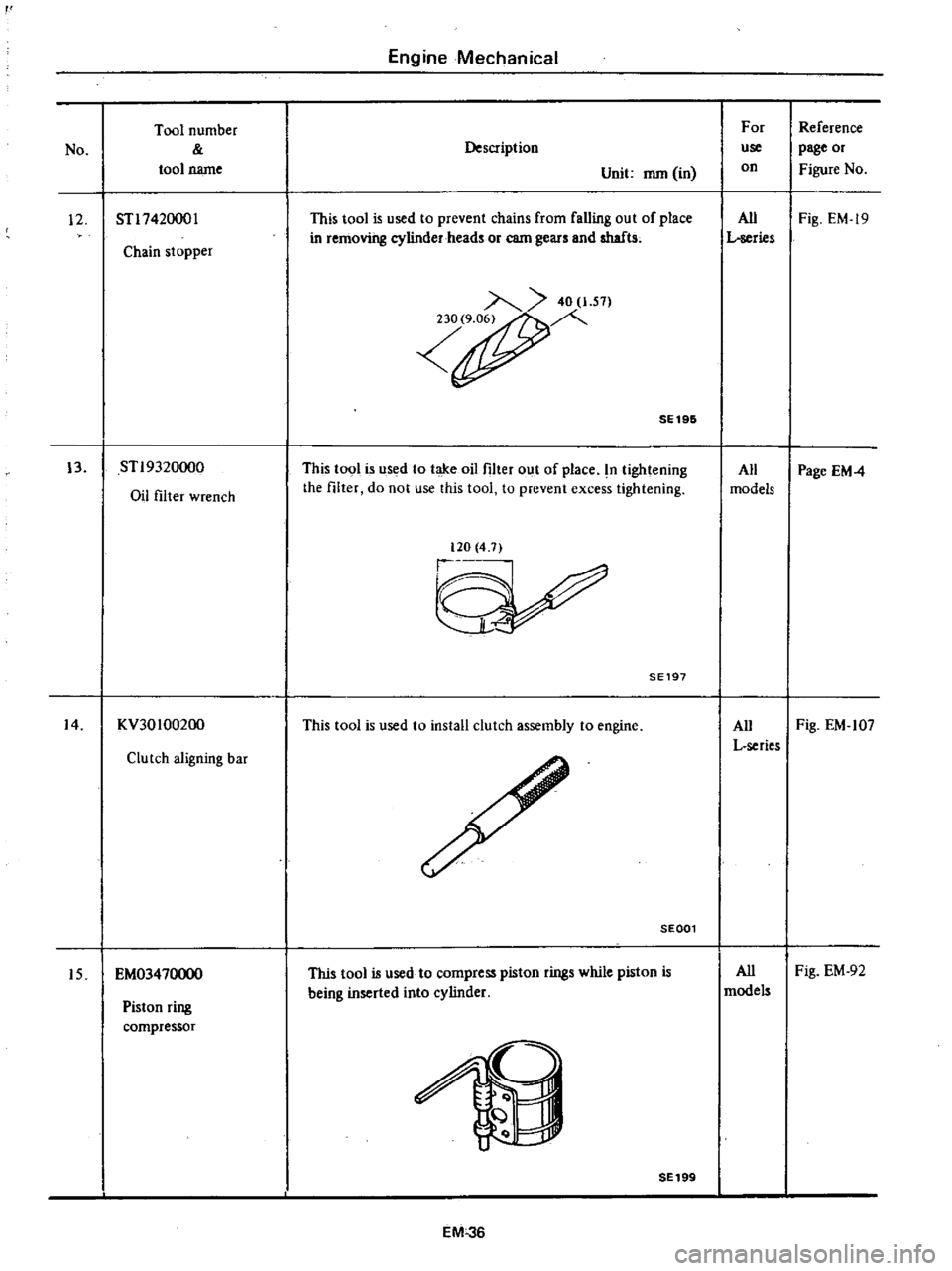
12
STl742000l
This
tool
is
used
to
prevent
chains
from
falling
out
of
place
All
Fig
EM
19
in
removing
cylinder
heads
or
earn
gears
and
shafts
L
series
Chain
stopper
40
1
S1
r
SE196
13
STl9320oo0
This
tool
is
used
to
take
oil
filter
out
of
place
n
tightening
All
Page
EM4
Oil
filter
wrench
the
filter
do
not
use
this
tool
to
prevent
excess
tightening
models
120
4
7
SE197
14
KV30100200
This
tool
is
used
to
install
clutch
assembly
to
engine
All
Fig
EM
107
L
series
Clutch
aligning
bar
SEGOl
Piston
ring
compressor
This
tool
is
used
to
compress
piston
rings
while
piston
is
being
inserted
into
cylinder
All
Fig
EM
92
models
15
EM03470000
2
SE199
EM
36
Page 84 of 537

DATSUN
PICK
UP
MODEL
620
SERIES
I
NISSAN
J
NISSAN
MOTOR
CO
LTD
TOKYO
JAPAN
SECTION
EL
ENGINE
LUBRICATION
SYSTEM
ENGINE
LUBRICATION
SYSTEM
EL
2
SERVICE
DATA
AND
EL
5
SPECIFICATIONS
TROUBLE
DIAGNOSES
AND
EL
5
CORRECTIONS
SPECIAL
SERVICE
TOOLS
EL
6
Page 85 of 537
ENGINE
LUBRICATION
SYSTEM
ENGINE
LUBRICATION
SYSTEM
CONTENTS
LUBRICATION
CIRCUIT
01
L
PUMP
Removal
Installation
Disassembly
and
assembly
EL
2
EL
2
EL
2
EL
2
EL
3
Inspection
OIL
PRESSURE
REGULATOR
VALVE
OIL
FILTER
RELIEF
VALVE
EL
3
EL
4
EL
4
EL
4
E
L049
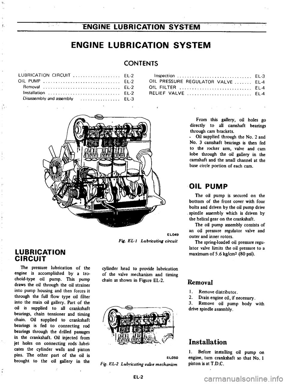
Fig
Elr
I
Lubricating
circuit
LUBRICATION
CIRCUIT
The
pressure
lubrication
of
the
engine
is
accomplished
by
a
tro
choid
type
oil
pump
This
pump
draws
the
oil
through
the
oil
strainer
into
pump
housing
and
then
forces
it
through
the
full
flow
type
oil
filter
into
the
main
oil
gallery
Part
of
the
oil
is
supplied
to
all
crankshaft
bearings
chain
tensioner
and
timing
chain
Oil
supplied
to
crankshaft
bearings
is
fed
to
connecting
rod
bearings
through
the
drilled
passages
in
the
crankshaft
Oil
injected
from
jet
holes
on
connecting
rods
Iubri
cates
the
cylinder
walls
and
piston
pins
The
other
part
of
the
oil
is
brought
to
the
oil
gallery
in
the
cylinder
head
to
provide
lubrication
of
the
valve
mechanism
and
timing
chain
as
shown
in
Figure
EL
2
ELOSO
Fig
EL
2
Lubricating
vallie
mechanism
EL
2
From
this
gallery
oil
holes
go
directly
to
all
camshaft
bearings
through
cam
brackets
Oil
supplied
through
the
No
2
and
No
3
camshaft
bearings
is
then
fed
to
the
rocker
arm
valve
and
eam
lobe
through
the
oil
gallery
in
the
camshaft
and
the
small
channel
at
the
base
circle
portion
of
each
earn
OIL
PUMP
The
oil
pump
is
secured
on
the
bottom
of
the
front
cover
with
four
bolts
and
driven
by
the
oil
pump
drive
spindle
assembly
which
is
driven
by
the
helical
gear
on
the
crankshaft
The
oil
pump
assembly
consists
of
an
oil
pressure
regulator
valve
and
outer
and
inn
r
rotors
The
spring
loaded
oil
pressure
regu
lator
valve
limits
the
oil
pressure
to
a
maximum
of
5
6
kg
em
80
psi
Removal
I
Remove
distributor
2
Drain
engine
oil
if
necessary
3
Remove
oil
pump
body
with
drive
spindle
assembly
Installation
I
Before
installing
oil
pump
on
engine
turn
crankshaft
so
that
No
I
piston
is
at
TD
C
Page 86 of 537
ENGINE
LUBRICATION
SYSTEM
2
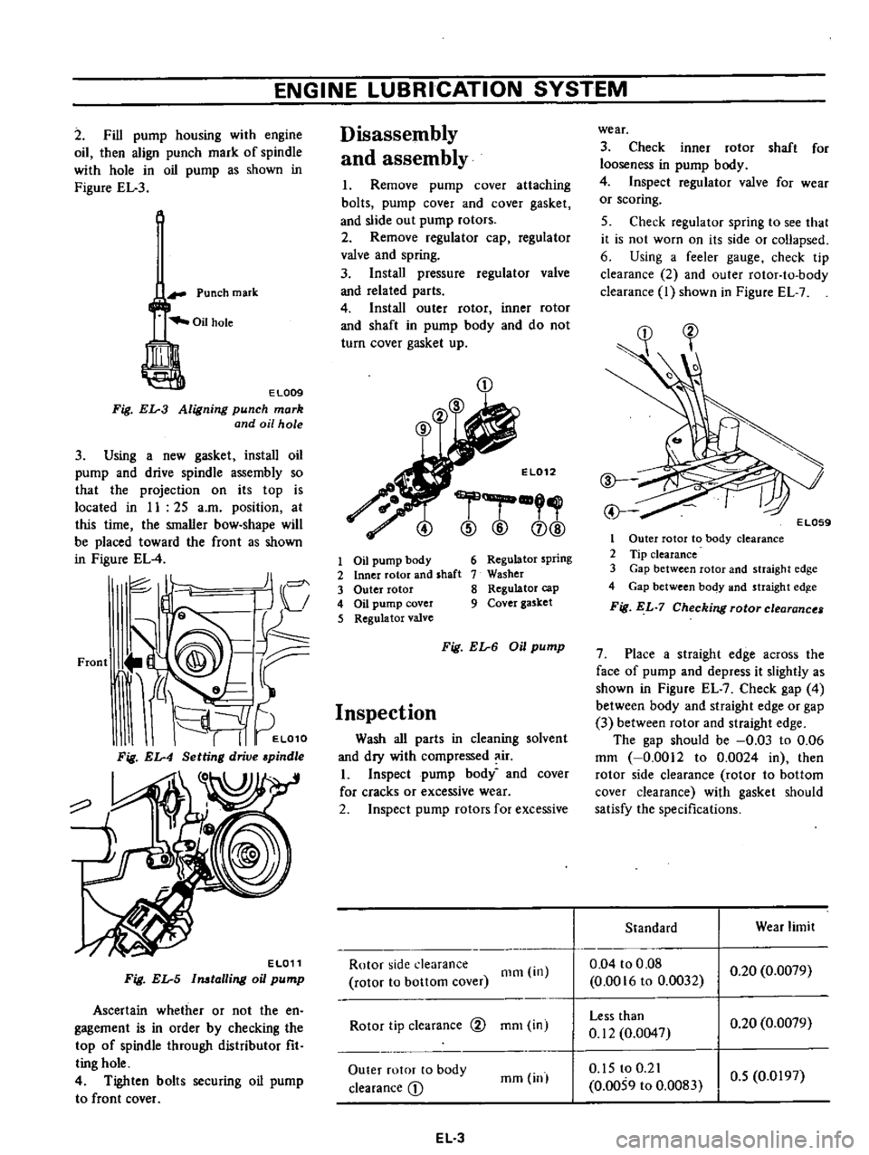
Fill
pump
housing
with
engine
oil
then
align
punch
mark
of
spindle
with
hole
in
oil
pump
as
shown
in
Figure
EL
3
Punch
mark
EL009
Fig
EL
3
Aligning
punch
mark
and
oil
hole
3
Using
a
new
gasket
install
oil
pump
and
drive
spindle
assembly
so
that
the
projection
on
its
top
is
located
in
II
25
a
m
position
at
this
time
the
smaller
bow
shape
will
be
placed
toward
the
front
as
shown
in
Figure
EL
4
JI
I
c
J
V
Front
J
@
9@
tr
i
d
L
It
I
I
EL010
Fig
EL
4
Setting
drive
pindle
o
EL011
Fig
EL
5
Imtalling
oil
pump
Ascertain
whether
or
not
the
en
gagement
is
in
order
by
checking
the
top
of
spindle
through
distributor
fit
ting
hole
4
Tighten
bolts
securing
oil
pump
to
front
cover
Disassembly
and
assembly
I
Remove
pump
cover
attaching
bolts
pump
cover
and
cover
gasket
and
slide
out
pump
rotors
2
Remove
regulator
cap
regulator
valve
and
spring
3
Install
pressure
regulator
valve
and
related
parts
4
Install
outer
rotor
inner
rotor
and
shaft
in
pump
body
and
do
not
turn
cover
gasket
up
CD
El012
r
@
@
CD@
1
Oil
pump
body
2
Inner
rotor
and
shaft
3
Outer
rotor
4
Oil
pump
cover
5
Regulator
valve
6
Regulator
spring
7
Washer
8
Regulator
cap
9
Cover
gasket
Fig
EL
6
Oil
pump
Inspection
Wash
all
parts
in
cleaning
solvent
and
dry
with
compressed
ir
I
Inspect
pump
body
and
cover
for
cracks
or
excessive
wear
2
Inspect
pump
rotors
for
excessive
Rotor
side
clearance
rotor
to
bottom
cover
Olm
in
Rotor
tip
clearance
@
mOl
in
Outer
rotor
to
body
clearance
D
mm
inl
EL
3
wear
3
Check
inner
rotor
shaft
for
looseness
in
pump
body
4
Inspect
regulator
valve
for
wear
or
scoring
5
Check
regulator
spring
to
see
that
it
is
not
worn
on
its
side
or
collapsed
6
Using
a
feeler
gauge
check
tip
clearance
2
and
outer
rotor
to
body
clearance
I
shown
in
Figure
EL
7
1
Outer
rotor
to
body
clearance
2
Tip
clearance
3
Gap
between
rotor
and
straight
edge
4
Gap
between
body
and
straight
edg
e
Fig
EL
7
Checking
rotor
clearance
7
Place
a
straight
edge
across
the
face
of
pump
and
depress
it
slightly
as
shown
in
Figure
EL
7
Check
gap
4
between
body
and
straight
edge
or
gap
3
between
rotor
and
straight
edge
The
gap
should
be
0
03
to
0
06
mm
0
0012
to
0
0024
in
then
rotor
side
clearance
rotor
to
bottom
cover
clearance
with
gasket
should
satisfy
the
specifications
Standard
Wear
limit
0
04
to
0
08
0
0016
to
0
0032
0
20
0
0079
Less
than
0
12
0
0047
0
20
0
0079
0
15
to
0
21
0
0059
to
0
0083
0
5
0
0197
Page 87 of 537
ENGINE
LUBRI
CATION
SYSTEM
Note
Pump
rotors
and
body
are
not
serviced
separately
If
pump
rotors
or
body
are
damaged
or
worn
replacement
of
the
entire
oil
pump
assembly
is
necessary
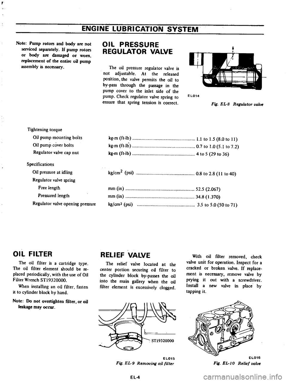
Tightening
torque
Oil
pump
mounting
bolts
Oil
pump
cover
bolts
Regulator
valve
cap
nut
Specifications
Oil
pressure
at
idling
Regulator
valve
spring
Free
length
Pressured
length
Regulator
valve
opening
pressure
OIL
FILTER
The
oil
filter
is
a
cartridge
type
The
oil
filter
element
should
be
reo
placed
periodically
with
the
use
of
Oil
Filter
Wrench
ST19320000
When
installing
an
oil
filter
fasten
it
to
cylinder
block
by
hand
Note
Do
not
overtighten
filter
or
oil
leakage
may
occur
OIL
PRESSURE
REGULATOR
VALVE
The
oil
pressure
regulator
valve
is
not
adjustable
At
the
released
position
the
valve
permits
the
oil
to
by
pass
through
the
passage
in
the
pump
cover
to
the
inlet
side
of
the
pump
Check
regulator
valve
spring
to
ensure
that
spring
tension
is
correct
kg
m
ft
Ib
kg
m
ft
lb
kg
m
ft
lb
kg
cm2
psi
mm
in
mm
in
kg
em
2
psi
RELIEF
VALVE
The
relief
valve
located
at
the
center
portion
securing
oil
fIlter
to
the
cylinder
block
by
passes
the
oil
into
the
main
gallery
when
the
oil
fIlter
element
is
excessively
clogged
STl9320000
EL015
Fig
EL
9
Removing
oil
filter
EL
4
EL014
Fig
EL
B
Regulator
value
l
l
to
1
5
8
0
to
11
0
7
to
1
0
5
Ito
7
2
4
to
5
29
to
36
0
8
to
2
8
II
to
40
52
5
2
067
34
8
1
370
35
to
5
0
50
to
71
With
oil
fIlter
removed
check
valve
unit
for
operation
Inspect
for
a
cracked
or
broken
valve
If
replace
ment
is
necessary
remove
valve
by
prying
it
out
with
a
screwdriver
Install
a
new
valve
in
place
by
tapping
it
EL016
Fig
EL
JO
Relief
lJOlue
Page 88 of 537
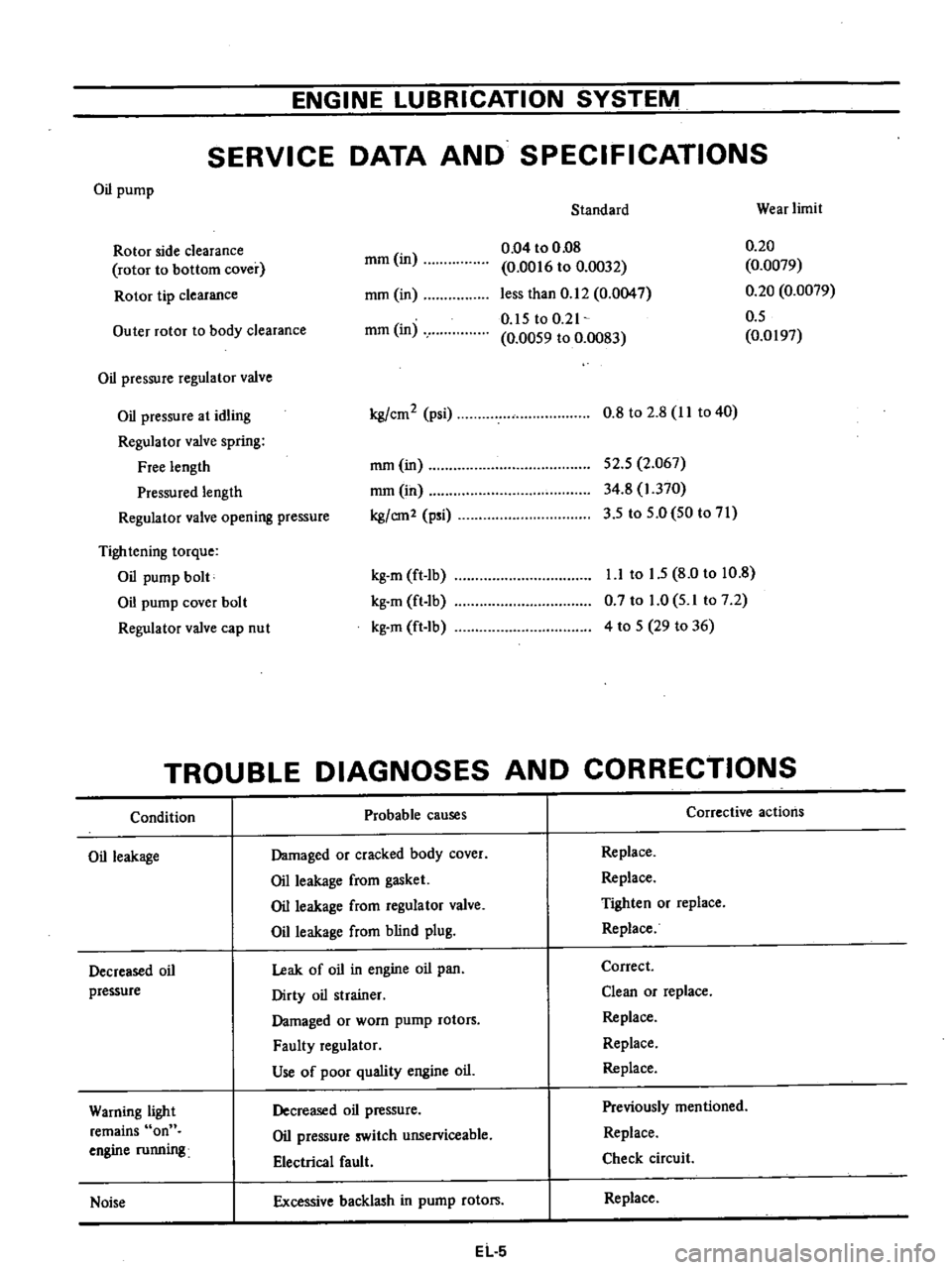
ENGINE
LUBRICATION
SYSTEM
SERVICE
DATA
AND
SPECIFICATIONS
Oil
pump
Standard
Wear
limit
mm
in
0
04
to
0
08
0
0016
to
0
0032
less
than
0
12
0
0047
0
15
toO
21
0
0059
to
0
0083
0
20
0
0079
0
20
0
0079
0
5
0
0197
Rotor
side
clearance
rotor
to
bottom
cover
Rotor
tip
clearance
mm
in
Outer
rotor
to
body
clearance
mm
in
Oil
pressure
regulator
valve
Oil
pressure
at
idling
Regulator
valve
spring
Free
length
Pressured
length
Regulator
valve
opening
pressure
kg
cm2
psi
0
8
to
2
8
II
to
40
mm
in
mmOn
kg
em2
psi
52
5
2
067
34
8
1
370
3
5
to
5
0
50
to
71
Tightening
torque
Oil
pump
bolt
Oil
pump
cover
bolt
Regulator
valve
cap
nut
kg
m
ft
lb
kg
m
ft
lb
kg
m
ft
Ib
1
1
to
1
5
8
0
to
10
8
0
7
to
1
0
5
1
to
7
2
4
to
5
29
to
36
TROUBLE
DIAGNOSES
AND
CORRECTIONS
Condition
Probable
causes
Corrective
actions
Oil
leakage
Damaged
or
cracked
body
cover
Oil
leakage
from
gasket
Oil
leakage
from
regulator
valve
Oil
leakage
from
blind
plug
Replace
Replace
Tighten
or
replace
Replace
Decreased
oil
pressure
Leak
of
oil
in
engine
oil
pan
Dirty
oil
strainer
Damaged
or
worn
pump
rotors
Faulty
regulator
Use
of
poor
quality
engine
oiL
Correct
Clean
or
replace
Replace
Replace
Replace
Warning
light
remains
on
engine
running
Decreased
oil
pressure
Oil
pressure
switch
unserviceable
Electrical
fault
Previously
mentioned
Replace
Check
circuit
Noise
Excessive
backlash
in
pump
rotors
Replace
EL
5
Page 89 of 537

No
Tool
number
tool
name
STl9320000
Oil
filter
wrench
ENGINE
LUBRICATION
SYSTEM
SPECIAL
SERVICE
TOOL
Description
Unit
nun
in
For
use
on
Reference
page
or
Figure
No
This
tool
is
used
to
take
oil
f1Iter
out
of
place
In
tightening
All
Fig
EL
9
the
f1Iter
do
not
use
this
tool
to
prevent
excess
tightening
models
I
120
4
7
SE197
EL
6