DODGE NEON 1999 Service Repair Manual
Manufacturer: DODGE, Model Year: 1999, Model line: NEON, Model: DODGE NEON 1999Pages: 1200, PDF Size: 35.29 MB
Page 1181 of 1200
EXHAUST GAS RECIRCULATION (EGR) SYSTEM
INDEX
page page
DESCRIPTION AND OPERATION
EXHAUST GAS RECIRCULATION (EGR)
SYSTEM............................. 18
DIAGNOSIS AND TESTING
EGR GAS FLOW TEST................... 19
EGR SYSTEM ON-BOARD DIAGNOSTICS..... 19
EGR SYSTEM TEST..................... 19EGR VALVE CONTROL (TRANSDUCER) TEST . 20
EGR VALVE LEAKAGE TEST............... 20
REMOVAL AND INSTALLATION
EGR TUBE............................. 22
EGRVALVE ............................ 21
SPECIFICATIONS
TORQUE.............................. 22
DESCRIPTION AND OPERATION
EXHAUST GAS RECIRCULATION (EGR) SYSTEM
Refer to Monitored Systems - EGR Monitor in this
group for more information.
The EGR system reduces oxides of nitrogen (NOx)
in engine exhaust and helps prevent detonation
(engine knock). Under normal operating conditions,
engine cylinder temperature can reach more than
3000ÉF. Formation of NOx increases proportionally
with combustion temperature. To reduce the emission
of these oxides, the cylinder temperature must be
lowered. The system allows a predetermined amount
of hot exhaust gas to recirculate and dilute the
incoming air/fuel mixture. The diluted air/fuel mix-
ture reduces peak flame temperature during combus-
tion.
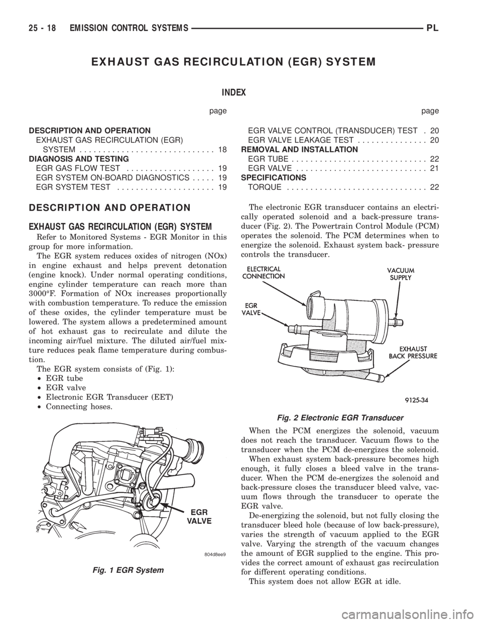
The EGR system consists of (Fig. 1):
²EGR tube
²EGR valve
²Electronic EGR Transducer (EET)
²Connecting hoses.The electronic EGR transducer contains an electri-
cally operated solenoid and a back-pressure trans-
ducer (Fig. 2). The Powertrain Control Module (PCM)
operates the solenoid. The PCM determines when to
energize the solenoid. Exhaust system back- pressure
controls the transducer.
When the PCM energizes the solenoid, vacuum
does not reach the transducer. Vacuum flows to the
transducer when the PCM de-energizes the solenoid.
When exhaust system back-pressure becomes high
enough, it fully closes a bleed valve in the trans-
ducer. When the PCM de-energizes the solenoid and
back-pressure closes the transducer bleed valve, vac-
uum flows through the transducer to operate the
EGR valve.
De-energizing the solenoid, but not fully closing the
transducer bleed hole (because of low back-pressure),
varies the strength of vacuum applied to the EGR
valve. Varying the strength of the vacuum changes
the amount of EGR supplied to the engine. This pro-
vides the correct amount of exhaust gas recirculation
for different operating conditions.
This system does not allow EGR at idle.
Fig. 1 EGR System
Fig. 2 Electronic EGR Transducer
25 - 18 EMISSION CONTROL SYSTEMSPL
Page 1182 of 1200
DIAGNOSIS AND TESTING
EGR SYSTEM ON-BOARD DIAGNOSTICS
The PCM performs an on-board diagnostic check of
the EGR system. The diagnostic system uses the
electronic EGR transducer for the system tests.
The diagnostic check activates only during selected
engine/driving conditions. When the conditions are
met, the PCM energizes the transducer solenoid to
disable the EGR. The PCM checks for a change in
the heated oxygen sensor signal. If the air-fuel mix-
ture goes lean, the PCM will attempt to enrichen the
mixture. The PCM registers a Diagnostic Trouble
Code (DTC) if the EGR system is not operating cor-
rectly. After registering a DTC, the PCM turns on the
malfunction indicator (Check Engine) lamp after 2
consecutive trips. There are 2 types of failures sensed
by the PCM. The first is a short or open in the elec-
trical solenoid circuit. the second is a mechhanical
failure or loss of vacuum. The Malfunction Indicator
Lamp (MIL) indicates the need for service.
If a problem is indicated by the MIL and a DTC for
the EGR system is set, check for proper operation of
the EGR system. Use the System Test, EGR Gas
Flow Test. If the EGR system tests properly, check
the system using the DRB scan tool. Refer to
On-Board Diagnosis sections in this Group. Also,
refer to the DRB scan tool and the appropriate Pow-
ertrain Diagnostics Procedure manual.
EGR SYSTEM TEST
WARNING: APPLY PARKING BRAKE AND/OR
BLOCK WHEELS BEFORE TESTING THE EGR SYS-
TEM.
(1) Check the condition of all EGR system hoses
and tubes for leaks, blockages, cracks, kinks and
hardening of rubber hoses. Repair and correct these
conditions before performing any tests.
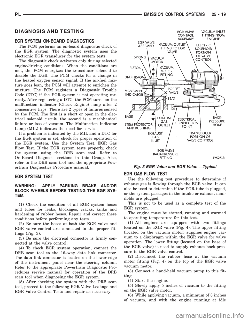
(2) Be sure the hoses at both the EGR valve and
EGR valve control are connected to the proper fit-
tings (Fig. 3).
(3) Be sure the electrical connector is firmly con-
nected at the valve control.
(4) To check EGR system operation, connect the
DRB scan tool to the 16±way data link connector.
The data link connector is located on the lower edge
of the instrument panel near the steering column.
Refer to the appropriate Powertrain Diagnostic Pro-
cedures service manual for operation of the DRB
scan tool when diagnosing the EGR system.
(5) After checking the system with the DRB scan
tool, proceed to the following EGR Valve Leakage and
EGR Valve Control Tests and repair as necessary.
EGR GAS FLOW TEST
Use the following test procedure to determine if
exhaust gas is flowing through the EGR valve. It can
also be used to determine if the EGR tube is plugged,
or the system passages in the intake or exhaust man-
ifolds are plugged.
This is not to be used as a complete test of the
EGR system.
The engine must be started, running and warmed
to operating temperature for this test.
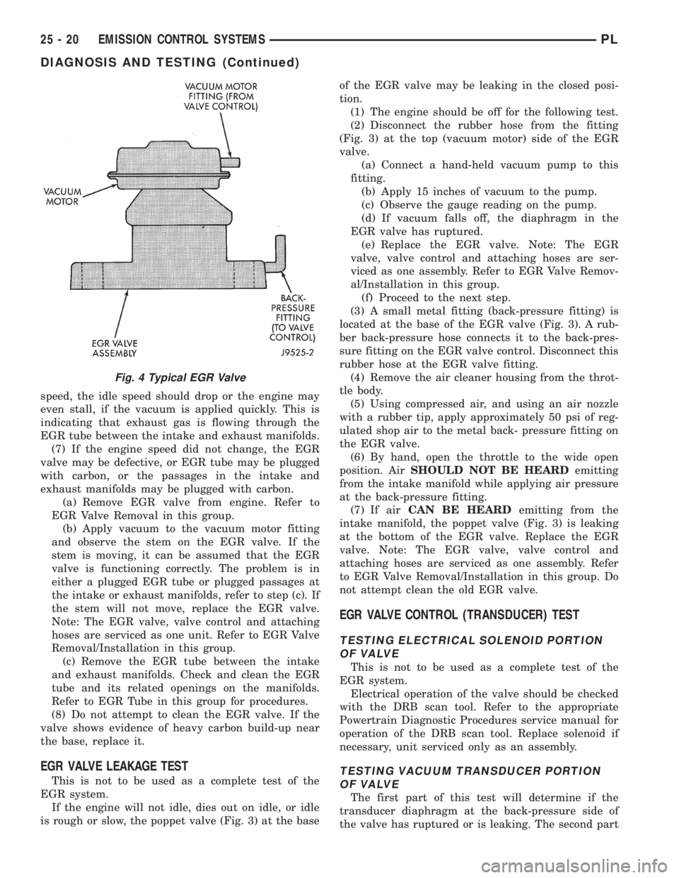
(1) All engines are equipped with two fittings
located on the EGR valve (Fig. 4). The upper fitting
(located on the vacuum motor) supplies engine vac-
uum to a diaphragm within the EGR valve for valve
operation. The lower fitting (located on the base of
the EGR valve) is used to supply exhaust back-pres-
sure to the EGR valve control.
(2) Disconnect the rubber hose at the vacuum
motor fitting (Fig. 4) on the top of the EGR valve
vacuum motor.
(3) Connect a hand-held vacuum pump to this fit-
ting.
(4) Start the engine.
(5) Slowly apply 5 inches of vacuum to the fitting
on the EGR valve motor.
(6) While applying vacuum, a minimum of 3 inches
of vacuum, and with the engine running at idle
Fig. 3 EGR Value and EGR Value ÐTypical
PLEMISSION CONTROL SYSTEMS 25 - 19
Page 1183 of 1200
speed, the idle speed should drop or the engine may
even stall, if the vacuum is applied quickly. This is
indicating that exhaust gas is flowing through the
EGR tube between the intake and exhaust manifolds.
(7) If the engine speed did not change, the EGR
valve may be defective, or EGR tube may be plugged
with carbon, or the passages in the intake and
exhaust manifolds may be plugged with carbon.
(a) Remove EGR valve from engine. Refer to
EGR Valve Removal in this group.
(b) Apply vacuum to the vacuum motor fitting
and observe the stem on the EGR valve. If the
stem is moving, it can be assumed that the EGR
valve is functioning correctly. The problem is in
either a plugged EGR tube or plugged passages at
the intake or exhaust manifolds, refer to step (c). If
the stem will not move, replace the EGR valve.
Note: The EGR valve, valve control and attaching
hoses are serviced as one unit. Refer to EGR Valve
Removal/Installation in this group.
(c) Remove the EGR tube between the intake
and exhaust manifolds. Check and clean the EGR
tube and its related openings on the manifolds.
Refer to EGR Tube in this group for procedures.
(8) Do not attempt to clean the EGR valve. If the
valve shows evidence of heavy carbon build-up near
the base, replace it.
EGR VALVE LEAKAGE TEST
This is not to be used as a complete test of the
EGR system.
If the engine will not idle, dies out on idle, or idle
is rough or slow, the poppet valve (Fig. 3) at the baseof the EGR valve may be leaking in the closed posi-
tion.
(1) The engine should be off for the following test.
(2) Disconnect the rubber hose from the fitting
(Fig. 3) at the top (vacuum motor) side of the EGR
valve.
(a) Connect a hand-held vacuum pump to this
fitting.
(b) Apply 15 inches of vacuum to the pump.
(c) Observe the gauge reading on the pump.
(d) If vacuum falls off, the diaphragm in the
EGR valve has ruptured.
(e) Replace the EGR valve. Note: The EGR
valve, valve control and attaching hoses are ser-
viced as one assembly. Refer to EGR Valve Remov-
al/Installation in this group.
(f) Proceed to the next step.
(3) A small metal fitting (back-pressure fitting) is
located at the base of the EGR valve (Fig. 3). A rub-
ber back-pressure hose connects it to the back-pres-
sure fitting on the EGR valve control. Disconnect this
rubber hose at the EGR valve fitting.
(4) Remove the air cleaner housing from the throt-
tle body.
(5) Using compressed air, and using an air nozzle
with a rubber tip, apply approximately 50 psi of reg-
ulated shop air to the metal back- pressure fitting on
the EGR valve.
(6) By hand, open the throttle to the wide open
position. AirSHOULD NOT BE HEARDemitting
from the intake manifold while applying air pressure
at the back-pressure fitting.
(7) If airCAN BE HEARDemitting from the
intake manifold, the poppet valve (Fig. 3) is leaking
at the bottom of the EGR valve. Replace the EGR
valve. Note: The EGR valve, valve control and
attaching hoses are serviced as one assembly. Refer
to EGR Valve Removal/Installation in this group. Do
not attempt clean the old EGR valve.
EGR VALVE CONTROL (TRANSDUCER) TEST
TESTING ELECTRICAL SOLENOID PORTION
OF VALVE
This is not to be used as a complete test of the
EGR system.
Electrical operation of the valve should be checked
with the DRB scan tool. Refer to the appropriate
Powertrain Diagnostic Procedures service manual for
operation of the DRB scan tool. Replace solenoid if
necessary, unit serviced only as an assembly.
TESTING VACUUM TRANSDUCER PORTION
OF VALVE
The first part of this test will determine if the
transducer diaphragm at the back-pressure side of
the valve has ruptured or is leaking. The second part
Fig. 4 Typical EGR Valve
25 - 20 EMISSION CONTROL SYSTEMSPL
DIAGNOSIS AND TESTING (Continued)
Page 1184 of 1200
of the test will determine if engine vacuum (full-man-
ifold) is flowing from the inlet to the outlet side of
the valve. This is not to be used as a complete test of
the EGR system.
(1) Disconnect the rubber back-pressure hose from
the fitting at the bottom of EGR valve (Fig. 3).
(2) Connect a hand-held vacuum pump to this fit-
ting.
(3) Apply 10 inches of vacuum to this fitting.
(4) If vacuum falls off, the valve diaphragm is
leaking.
(5) Replace the Complete EGR valve assembly.
Proceed to next step for further testing.
(6) Reconnect hose to EGR valve.
(7) Remove the vacuum supply hose at the vacuum
inletfitting (Fig. 3) on the EGR solenoid.
(8) Connect a vacuum gauge to this disconnected
vacuum line.
(9) Start the engine and bring to operating tem-
perature. Hold engine speed at approximately 1500
rpm.
(10) Check for steady engine vacuum (full-mani-
fold) at this hose.
(11) If engine vacuum (full-manifold) is not
present, check vacuum line to engine and repair as
necessary before proceeding to next step.
(12) Reconnect the rubber hose to the vacuum
inletfitting (Fig. 3) on the EGR valve.
(13) Disconnect the rubber hose at the vacuum
outletfitting (Fig. 3) on the EGR valve.
(14) Connect a vacuum gauge to this fitting.
(15) Disconnect the electrical connector (Fig. 3) at
the valve control. This will simulate an open circuit
(no ground from the PCM) at the valve, activating
the valve. A DTC will be set in the PCM that must
be erased after testing is complete.
(16) Start the engine and bring to operating tem-
perature.
(17) Hold the engine speed to approximately 2000
rpm while checking for engine vacuum (full-manifold)
at this fitting.To allow full manifold vacuum to
flow through the valve, exhaust back-pressure
must be present at valve. It must be high
enough to hold the bleed valve in the trans-
ducer portion of the valve closed.Have a helper
momentarily (a second or two) hold a rag over the
tailpipe opening to build some exhaust back-pressure
while observing the vacuum gauge. Heavy gloves
should be worn.Do not cover the tailpipe open-
ing for an extended period of time as damage to
components or overheating may result.(18) As temporary back-pressure is built, full man-
ifold vacuum should be observed at the vacuum out-
let fitting. Without back-pressure, and engine at
approximately 2000 rpm, the gauge reading will be
low. This low reading is normal. At idle speed, the
gauge reading may be erratic. This is also normal.
(19) If full manifold vacuum is not present at the
outlet fitting, but was present at the inlet fitting,
replace the valve. Note: The EGR valve, valve control
and attaching hoses are serviced as one assembly.
Refer to EGR Valve Removal/Installation in this
group.
REMOVAL AND INSTALLATION
EGR VALVE
If the EGR system operates incorrectly, replace the
entire EGR valve and transducer together. The EGR
valve and electrical transducer are calibrated
together.
REMOVAL
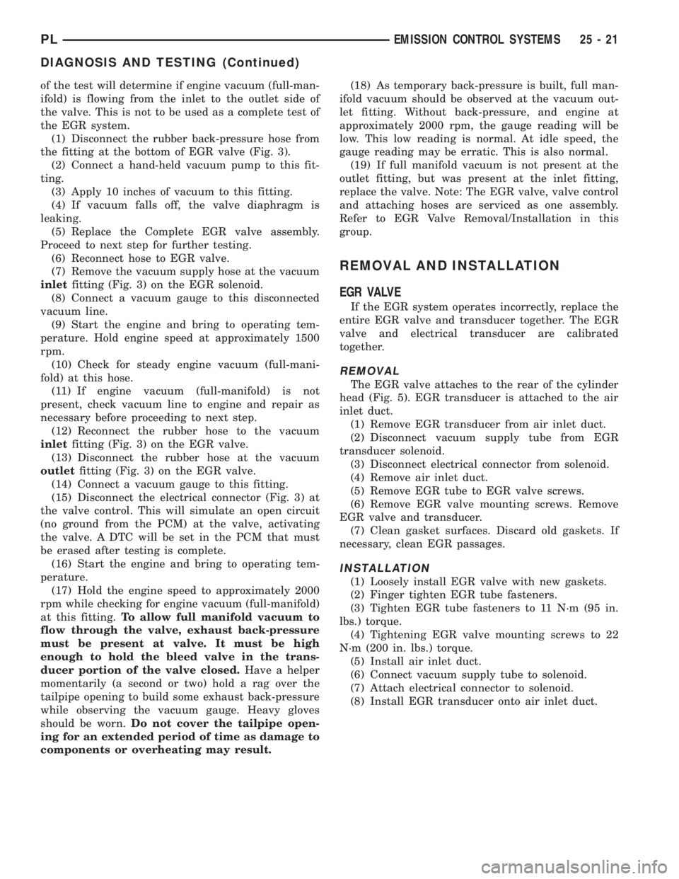
The EGR valve attaches to the rear of the cylinder
head (Fig. 5). EGR transducer is attached to the air
inlet duct.
(1) Remove EGR transducer from air inlet duct.
(2) Disconnect vacuum supply tube from EGR
transducer solenoid.
(3) Disconnect electrical connector from solenoid.
(4) Remove air inlet duct.
(5) Remove EGR tube to EGR valve screws.
(6) Remove EGR valve mounting screws. Remove
EGR valve and transducer.
(7) Clean gasket surfaces. Discard old gaskets. If
necessary, clean EGR passages.
INSTALLATION
(1) Loosely install EGR valve with new gaskets.
(2) Finger tighten EGR tube fasteners.
(3) Tighten EGR tube fasteners to 11 N´m (95 in.
lbs.) torque.
(4) Tightening EGR valve mounting screws to 22
N´m (200 in. lbs.) torque.
(5) Install air inlet duct.
(6) Connect vacuum supply tube to solenoid.
(7) Attach electrical connector to solenoid.
(8) Install EGR transducer onto air inlet duct.
PLEMISSION CONTROL SYSTEMS 25 - 21
DIAGNOSIS AND TESTING (Continued)
Page 1185 of 1200
EGR TUBE
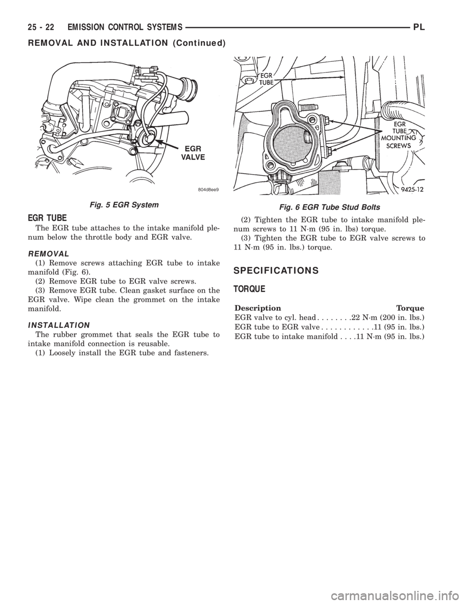
The EGR tube attaches to the intake manifold ple-
num below the throttle body and EGR valve.
REMOVAL
(1) Remove screws attaching EGR tube to intake
manifold (Fig. 6).
(2) Remove EGR tube to EGR valve screws.
(3) Remove EGR tube. Clean gasket surface on the
EGR valve. Wipe clean the grommet on the intake
manifold.
INSTALLATION
The rubber grommet that seals the EGR tube to
intake manifold connection is reusable.
(1) Loosely install the EGR tube and fasteners.(2) Tighten the EGR tube to intake manifold ple-
num screws to 11 N´m (95 in. lbs) torque.
(3) Tighten the EGR tube to EGR valve screws to
11 N´m (95 in. lbs.) torque.
SPECIFICATIONS
TORQUE
Description Torque
EGR valve to cyl. head........22N´m(200 in. lbs.)
EGR tube to EGR valve............11(95in.lbs.)
EGR tube to intake manifold....11N´m(95in.lbs.)
Fig. 5 EGR SystemFig. 6 EGR Tube Stud Bolts
25 - 22 EMISSION CONTROL SYSTEMSPL
REMOVAL AND INSTALLATION (Continued)
Page 1186 of 1200
EMISSION CONTROL SYSTEMÐ1.8L ENGINE
CONTENTS
page page
GENERAL INFORMATION
EMISSION CONTROL SYSTEMÐ1.8L SOHC
ENGINE............................. 1
GENERAL INFORMATION
EMISSION CONTROL SYSTEMÐ1.8L SOHC
ENGINE
The emission control system used on the 1.8L
SOHC engine operates the same as the emission con-
trol system used on the 2.0L SOHC engine. It alsocontains the same components as the 2.0L engine,
and the service procedures are the same. Refer to
group 25 for the 2.0L engine in this manual for a
complete description of the fuel system and its ser-
vice procedures.
PLEMISSION CONTROL SYSTEMÐ1.8L ENGINE 25 - 1
Page 1187 of 1200

Page 1188 of 1200
INTRODUCTION
CONTENTS
page page
GENERAL INFORMATION
BODY CODE EMBOSS.................... 3
BODY CODE EMBOSS/PLATE............... 2
BODY CODE PLATE...................... 3
FASTENER IDENTIFICATION................ 5INTERNATIONAL VEHICLE CONTROL AND
DISPLAY SYMBOLS.................... 5
METRIC SYSTEM........................ 8
STANDARD BODY DIMENSIONS............ 4
TORQUE REFERENCES................... 10
VEHICLE IDENTIFICATION NUMBER......... 1
VEHICLE SAFETY CERTIFICATION LABEL..... 2
GENERAL INFORMATION
VEHICLE IDENTIFICATION NUMBER
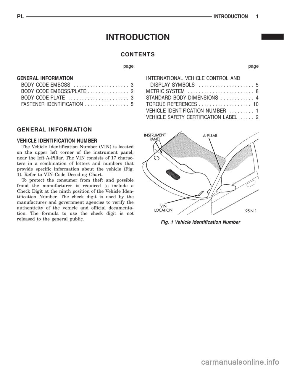
The Vehicle Identification Number (VIN) is located
on the upper left corner of the instrument panel,
near the left A-Pillar. The VIN consists of 17 charac-
ters in a combination of letters and numbers that
provide specific information about the vehicle (Fig.
1). Refer to VIN Code Decoding Chart.
To protect the consumer from theft and possible
fraud the manufacturer is required to include a
Check Digit at the ninth position of the Vehicle Iden-
tification Number. The check digit is used by the
manufacturer and government agencies to verify the
authenticity of the vehicle and official documenta-
tion. The formula to use the check digit is not
released to the general public.
Fig. 1 Vehicle Identification Number
PLINTRODUCTION 1
Page 1189 of 1200
VEHICLE SAFETY CERTIFICATION LABEL
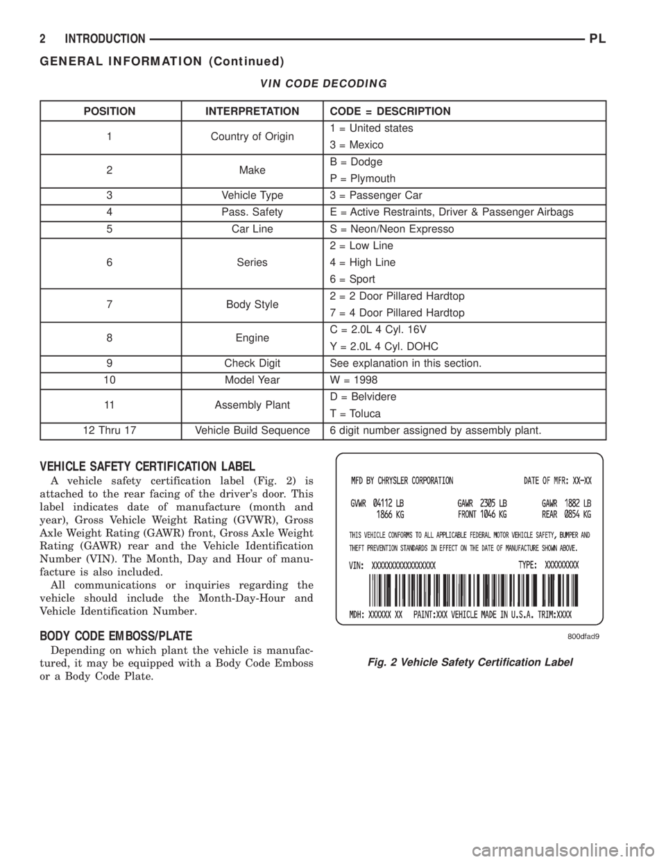
A vehicle safety certification label (Fig. 2) is
attached to the rear facing of the driver's door. This
label indicates date of manufacture (month and
year), Gross Vehicle Weight Rating (GVWR), Gross
Axle Weight Rating (GAWR) front, Gross Axle Weight
Rating (GAWR) rear and the Vehicle Identification
Number (VIN). The Month, Day and Hour of manu-
facture is also included.
All communications or inquiries regarding the
vehicle should include the Month-Day-Hour and
Vehicle Identification Number.
BODY CODE EMBOSS/PLATE
Depending on which plant the vehicle is manufac-
tured, it may be equipped with a Body Code Emboss
or a Body Code Plate.
VIN CODE DECODING
POSITION INTERPRETATION CODE = DESCRIPTION
1 Country of Origin1 = United states
3 = Mexico
2 MakeB = Dodge
P = Plymouth
3 Vehicle Type 3 = Passenger Car
4 Pass. Safety E = Active Restraints, Driver & Passenger Airbags
5 Car Line S = Neon/Neon Expresso
6 Series2 = Low Line
4 = High Line
6 = Sport
7 Body Style2 = 2 Door Pillared Hardtop
7 = 4 Door Pillared Hardtop
8 EngineC = 2.0L 4 Cyl. 16V
Y = 2.0L 4 Cyl. DOHC
9 Check Digit See explanation in this section.
10 Model Year W = 1998
11 Assembly PlantD = Belvidere
T = Toluca
12 Thru 17 Vehicle Build Sequence 6 digit number assigned by assembly plant.
Fig. 2 Vehicle Safety Certification Label
2 INTRODUCTIONPL
GENERAL INFORMATION (Continued)
Page 1190 of 1200
BODY CODE EMBOSS
The Body Code Emboss is located in the engine
compartment on the front of the right strut tower.
There are two lines of information in the body code
emboss.
BODY CODE EMBOSS LINE 1
Line 1 contains the Vehicle Identification Number
(VIN). Refer to Vehicle Identification Number (VIN)
paragraph for proper breakdown of VIN code.
BODY CODE EMBOSS LINE 2
DIGITS 1-3ÐPaint Code
Refer to Group 23, Body for paint information.
DIGITS 4-7ÐTrim Code
Refer to Parts Catalog for more information.
DIGITS 5-10ÐOpen
DIGITS 11-14ÐVehicle Order Number
BODY CODE PLATE
LOCATION AND DECODING
The Body Code Plate is located in the engine com-
partment on the radiator closure panel. There are
seven lines of information on the body code plate.
Lines 4, 5, 6, and 7 are not used to define service
information. Information reads from left to right,
starting with line 3 in the center of the plate to line
1 at the bottom of the plate.
BODY CODE PLATE ± LINE 3
DIGITS 1, 2, AND 3
Paint procedure
DIGIT 4
Open Space
DIGITS 5 THROUGH 8
Primary paint
See Group 23, Body for color codes.
DIGIT 9
Open Space
DIGITS 10 THROUGH 13
Secondary Paint
DIGIT 14
Open Space
DIGITS 15 THROUGH 18
Interior Trim Code
DIGIT 19
Open SpaceDIGITS 20, 21, AND 22
Engine Code
²ECB = 2.0L Four Cylinder SOHC Gasoline
²ECC = 2.0L Four Cylinder DOHC Gasoline
BODY CODE PLATE LINE 2
DIGITS 1 THROUGH 12
Vehicle Order Number
DIGITS 13, THROUGH 15
Vinyl Roof Code
DIGITS 16 AND 17
Open space
DIGITS 18 AND 19
Vehicle Shell Line
²PL
DIGITS 20
Carline
²C = Chrysler
²D = Dodge
²H = Plymouth
DIGIT 21
Price Class
²E = Economy
²H = High Line
²L = Low Line
²M = Mid Line
²P = Premium
²S = Special/Sport
²X = Performance Image
DIGITS 20 AND 21
Body Type
²22 = Two Door Sedan
²42 = Four Door Sedan
BODY CODE PLATE LINE 1
DIGITS 1, 2, AND 3
Transaxle Codes
²DGA = 31TH 3-Speed Automatic Transaxle
²DD4 = NV T350 5-Speed Manual Transaxle
²DD5 = NV T350 5-Speed Manual Transaxle
DIGIT 4
Open Space
PLINTRODUCTION 3
GENERAL INFORMATION (Continued)