DODGE NEON 1999 Service Repair Manual
Manufacturer: DODGE, Model Year: 1999, Model line: NEON, Model: DODGE NEON 1999Pages: 1200, PDF Size: 35.29 MB
Page 161 of 1200
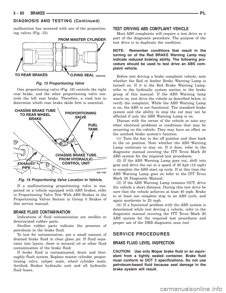
malfunction has occurred with one of the proportion-
ing valves (Fig. 15).
One proportioning valve (Fig. 16) controls the right
rear brake, and the other proportioning valve con-
trols the left rear brake. Therefore, a road test to
determine which rear brake skids first is essential.
If a malfunctioning proportioning valve is sus-
pected on a vehicle equipped with ABS brakes, refer
to Proportioning Valve Test With ABS Brakes in the
Proportioning Valves Section in Group 5 Brakes of
this service manual.
BRAKE FLUID CONTAMINATION
Indications of fluid contamination are swollen or
deteriorated rubber parts.
Swollen rubber parts indicate the presence of
petroleum in the brake fluid.
To test for contamination, put a small amount of
drained brake fluid in clear glass jar. If fluid sepa-
rates into layers, there is mineral oil or other fluid
contamination of the brake fluid.
If brake fluid is contaminated, drain and thor-
oughly flush system. Replace master cylinder, propor-
tioning valve, caliper seals, wheel cylinder seals,
Antilock Brakes hydraulic unit and all hydraulic
fluid hoses.
TEST DRIVING ABS COMPLAINT VEHICLE
Most ABS complaints will require a test drive as a
part of the diagnostic procedure. The purpose of the
test drive is to duplicate the condition.
NOTE: Remember conditions that result in the
turning on of the Red BRAKE Warning Lamp may
indicate reduced braking ability. The following pro-
cedure should be used to test drive an ABS com-
plaint vehicle.
Before test driving a brake complaint vehicle, note
whether the Red or Amber Brake Warning Lamp is
turned on. If it is the Red Brake Warning Lamp,
refer to the hydraulic system section in the brake
group of this manual. If the ABS Warning lamp
was/is on, test drive the vehicle as described below, to
verify the complaint. While the ABS Warning Lamp
is on, the ABS is not functional. The standard brake
system and the ability to stop the car may not be
affected if only the ABS Warning Lamp is on.
Discuss with the owner of the vehicle or note any
other electrical problems or conditions that may be
occurring on the vehicle. They may have an effect on
the antilock brake system's function.
(1) Turn the key to the off position and then back
to the on position. Note whether the ABS Warning
Lamp continues to stay on. If it does, refer to the
diagnostic manual covering the ITT Teves Mark 20
ABS system for the required test procedures.
(2) If the ABS Warning Lamp goes out, shift into
gear and drive the car to a speed of 20 kph (12 mph)
to complete the ABS start up cycle. If at this time the
ABS Warning Lamp goes on refer to the ITT Teves
Mark 20 Diagnostic Manual.
(3) If the ABS Warning Lamp remains OUT, drive
the vehicle a short distance. During this test drive be
sure that the vehicle achieves at least 40 mph. Brake
to at least one complete stop in an ABS cycle, and
again accelerate to 25 mph.
(4) If a functional problem with the ABS system is
determined while test driving a vehicle, refer to the
diagnostic manual covering the ITT Teves Mark 20
ABS system for the required test procedures and
proper use of the DRB diagnostic scan tool.
SERVICE PROCEDURES
BRAKE FLUID LEVEL INSPECTION
CAUTION: Use only Mopar brake fluid or an equiv-
alent from a tightly sealed container. Brake fluid
must conform to DOT 3 specifications. Do not use
petroleum-based fluid because seal damage in the
brake system will result.
Fig. 15 Proportioning Valve
Fig. 16 Proportioning Valve Location In Vehicle
5 - 80 BRAKESPL
DIAGNOSIS AND TESTING (Continued)
Page 162 of 1200
For the specific procedure covering the inspection
of the brake fluid level and adding brake fluid to the
reservoir, refer to the Service Adjustments Section in
this group of the service manual.
BLEEDING TEVES MARK 20 HYDRAULIC SYSTEM
The hydraulic system for the base brakes must be
bled anytime air enters the hydraulic system. Air can
enter the hydraulic system for the base brakes due to
the disconnection of brake lines, hoses or any other
hydraulically operated component of the base brake
system. The ABS system, particularly the ICU,
should only be bled when the ICU is replaced or it is
removed from the vehicle. The ICU must also always
be bled if for any reason it is suspected that the ICU
has ingested air. Under most circumstances that
require the bleeding of the brakes hydraulic system,
only the base brake hydraulic system needs to be
bled.
It is important to note that excessive air in the
brake system will cause a soft or spongy feeling
brake pedal.
During the brake bleeding procedure, be sure the
brake fluid level remains close to the FULL level in
the master cylinder fluid reservoir. Check the fluid
level periodically during the bleeding procedure and
add DOT 3 brake fluid as required.
The ITT Teves Mark 20 ABS must be bled as two
independent braking systems. The non ABS portion
of the brake system is to be bled the same as any
non ABS system. Refer to the Service Adjustments
section in this manual for the proper bleeding proce-
dure to be used. This brake system can be either
pressure bled or manually bled.
The ABS portion of the brake system MUST be
bled separately. This bleeding procedure requires the
use of the DRB Diagnostic Tester and the bleeding
sequence procedure outlined below.
ABS BLEEDING PROCEDURE
When bleeding the ABS system, the following
bleeding sequenceMUSTbe followed to insure com-
plete and adequate bleeding. The ABS system can be
bled using a manual bleeding procedure or standard
pressure bleeding equipment.
If the brake system is to be bled using pressurized
bleeding equipment, refer to Bleeding Brake System
in the Service Adjustments section at the beginning
of this group for proper equipment usage and proce-
dures.
(1) Assemble and install all brake system compo-
nents on the vehicle making sure all hydraulic fluid
lines are installed and properly torqued.
(2) Connect the DRB Diagnostics Tester to the
diagnostics connector. The Teves Mark 20 ABS diag-
nostic connector is located under the instrument
panel to the left of the steering column cover.(3) Using the DRB, check to make sure the CAB
does not have any fault codes stored. If it does,
remove them using the DRB.
WARNING: WHEN BLEEDING THE BRAKE SYS-
TEM WEAR SAFETY GLASSES. A CLEAR BLEED
TUBE MUST BE ATTACHED TO THE BLEEDER
SCREWS AND SUBMERGED IN A CLEAR CON-
TAINER FILLED PART WAY WITH CLEAN BRAKE
FLUID. DIRECT THE FLOW OF BRAKE FLUID AWAY
FROM THE PAINTED SURFACES OF THE VEHICLE.
BRAKE FLUID AT HIGH PRESSURE MAY COME
OUT OF THE BLEEDER SCREWS WHEN OPENED.
(4) Bleed the base brake system using the stan-
dard pressure or manual bleeding procedure as out-
lined in the Service Adjustments section of this
service manual.
(5) Using the DRB, go to the9Bleed ABS9routine.
Apply the brake pedal firmly and initiate the9Bleed
ABS9cycle one time. Release the brake pedal.
(6) Bleed the base brake system again, as in step
Step 4 above.
(7) Repeat steps Step 5 and Step 6 above until
brake fluid flows clear and is free of any air bubbles.
Check brake fluid level in reservoir periodically to
prevent reservoir from running low on brake fluid.
(8) Test drive the vehicle to be sure brakes are
operating correctly and that the brake pedal does not
feel spongy.
REMOVAL AND INSTALLATION
ABS GENERAL SERVICE PRECAUTIONS
CAUTION: Review this entire section prior to per-
forming any mechanical work on a vehicle equipped
with the ITT Tevis Mark 20 ABS brake system. This
section contains information on precautions per-
taining to potential component damage, vehicle
damage and personal injury which could result
when servicing an ABS equipped vehicle.
CAUTION: Only the recommended jacking or hoist-
ing positions for this vehicle are to be used when-
ever it is necessary to lift a vehicle. Failure to raise
a vehicle from the recommended locations could
result in lifting a vehicle by the hydraulic control
unit mounting bracket. Lifting a vehicle by the
hydraulic control unit mounting bracket will result
in damage to the mounting bracket and the hydrau-
lic control unit.
PLBRAKES 5 - 81
SERVICE PROCEDURES (Continued)
Page 163 of 1200
CAUTION: Certain components of the ABS System
are not intended to be serviced individually.
Attempting to remove or disconnect certain system
components may result in improper system opera-
tion. Only those components with approved
removal and installation procedures in this manual
should be serviced.
CAUTION: Brake fluid will damage painted sur-
faces. If brake fluid is spilled on any painted sur-
faces, wash off with water immediately.
CAUTION: When performing any service procedure
on a vehicle equipped with ABS do not apply a 12
volt power source to the ground circuit of the pump
motor in the HCU. Doing this will damage the pump
motor and will require replacement of the entire
HCU.
The following are general cautions which should be
observed when servicing the ABS system and/or
other vehicle systems. Failure to observe these pre-
cautions may result in ABS System component dam-
age.
If welding work is to be performed on the vehicle,
using an electric arc welder, the CAB connector
should be disconnected during the welding operation.
The CAB 25 way connector connector should never
be connected or disconnected with the ignition switch
in the ON position.
Many components of the ABS System are not ser-
viceable and must be replaced as an assembly. Do not
disassemble any component which is not designed to
be serviced.
ABS HYDRAULIC CONTROL UNIT
REMOVE
(1) Disconnect negative (ground) cable from the
battery and isolate cable.
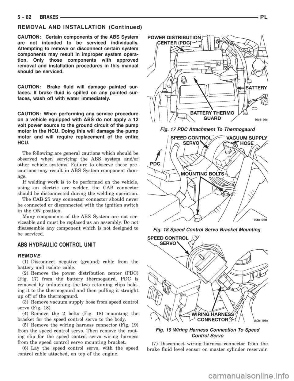
(2) Remove the power distribution center (PDC)
(Fig. 17) from the battery thermogaurd. PDC is
removed by unlatching the two retaining clips hold-
ing it to the thermogaurd and then pulling it straight
up off of the thermogaurd.
(3) Remove vacuum supply hose from speed control
servo (Fig. 18).
(4) Remove the 2 bolts (Fig. 18) mounting the
bracket for the speed control servo to the body.
(5) Remove the wiring harness connector (Fig. 19)
from the speed control servo. Then remove the rout-
ing clip for the speed control servo wiring harness
from the speed control servo mounting bracket.
(6) Lay the speed control servo, with the speed
control cable attached, on top of the engine.(7) Disconnect wiring harness connector from the
brake fluid level sensor on master cylinder reservoir.
Fig. 17 PDC Attachment To Thermogaurd
Fig. 18 Speed Control Servo Bracket Mounting
Fig. 19 Wiring Harness Connection To Speed
Control Servo
5 - 82 BRAKESPL
REMOVAL AND INSTALLATION (Continued)
Page 164 of 1200
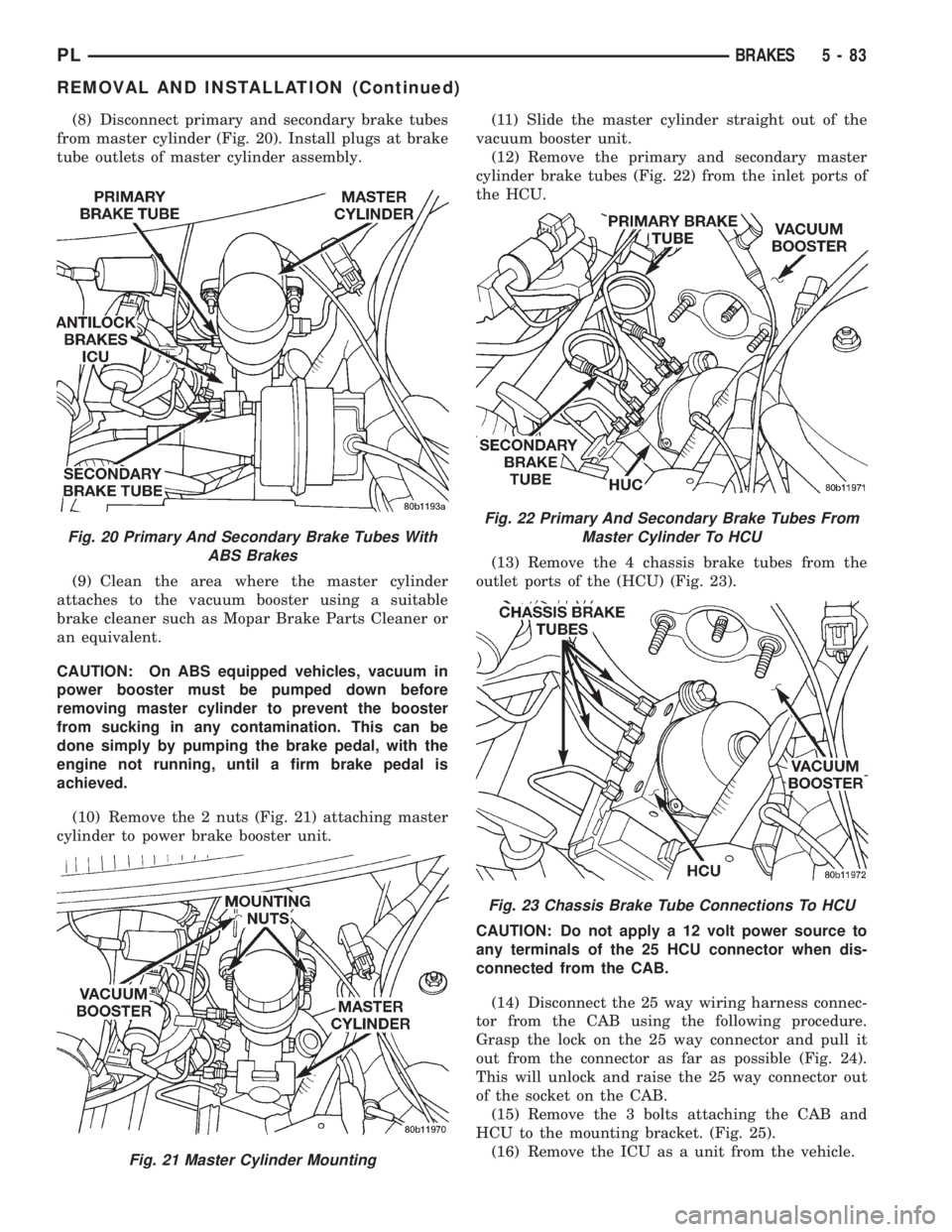
(8) Disconnect primary and secondary brake tubes
from master cylinder (Fig. 20). Install plugs at brake
tube outlets of master cylinder assembly.
(9) Clean the area where the master cylinder
attaches to the vacuum booster using a suitable
brake cleaner such as Mopar Brake Parts Cleaner or
an equivalent.
CAUTION: On ABS equipped vehicles, vacuum in
power booster must be pumped down before
removing master cylinder to prevent the booster
from sucking in any contamination. This can be
done simply by pumping the brake pedal, with the
engine not running, until a firm brake pedal is
achieved.
(10) Remove the 2 nuts (Fig. 21) attaching master
cylinder to power brake booster unit.(11) Slide the master cylinder straight out of the
vacuum booster unit.
(12) Remove the primary and secondary master
cylinder brake tubes (Fig. 22) from the inlet ports of
the HCU.
(13) Remove the 4 chassis brake tubes from the
outlet ports of the (HCU) (Fig. 23).
CAUTION: Do not apply a 12 volt power source to
any terminals of the 25 HCU connector when dis-
connected from the CAB.
(14) Disconnect the 25 way wiring harness connec-
tor from the CAB using the following procedure.
Grasp the lock on the 25 way connector and pull it
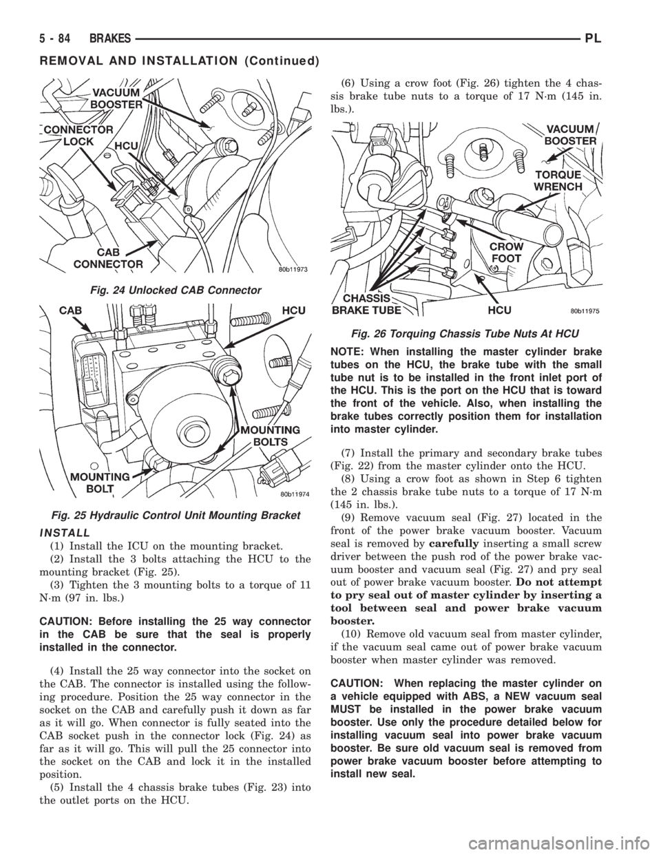
out from the connector as far as possible (Fig. 24).
This will unlock and raise the 25 way connector out
of the socket on the CAB.
(15) Remove the 3 bolts attaching the CAB and
HCU to the mounting bracket. (Fig. 25).
(16) Remove the ICU as a unit from the vehicle.
Fig. 20 Primary And Secondary Brake Tubes With
ABS Brakes
Fig. 21 Master Cylinder Mounting
Fig. 22 Primary And Secondary Brake Tubes From
Master Cylinder To HCU
Fig. 23 Chassis Brake Tube Connections To HCU
PLBRAKES 5 - 83
REMOVAL AND INSTALLATION (Continued)
Page 165 of 1200
INSTALL
(1) Install the ICU on the mounting bracket.
(2) Install the 3 bolts attaching the HCU to the
mounting bracket (Fig. 25).
(3) Tighten the 3 mounting bolts to a torque of 11
N´m (97 in. lbs.)
CAUTION: Before installing the 25 way connector
in the CAB be sure that the seal is properly
installed in the connector.
(4) Install the 25 way connector into the socket on
the CAB. The connector is installed using the follow-
ing procedure. Position the 25 way connector in the
socket on the CAB and carefully push it down as far
as it will go. When connector is fully seated into the
CAB socket push in the connector lock (Fig. 24) as
far as it will go. This will pull the 25 connector into
the socket on the CAB and lock it in the installed
position.
(5) Install the 4 chassis brake tubes (Fig. 23) into
the outlet ports on the HCU.(6) Using a crow foot (Fig. 26) tighten the 4 chas-
sis brake tube nuts to a torque of 17 N´m (145 in.
lbs.).
NOTE: When installing the master cylinder brake
tubes on the HCU, the brake tube with the small
tube nut is to be installed in the front inlet port of
the HCU. This is the port on the HCU that is toward
the front of the vehicle. Also, when installing the
brake tubes correctly position them for installation
into master cylinder.
(7) Install the primary and secondary brake tubes
(Fig. 22) from the master cylinder onto the HCU.
(8) Using a crow foot as shown in Step 6 tighten
the 2 chassis brake tube nuts to a torque of 17 N´m
(145 in. lbs.).
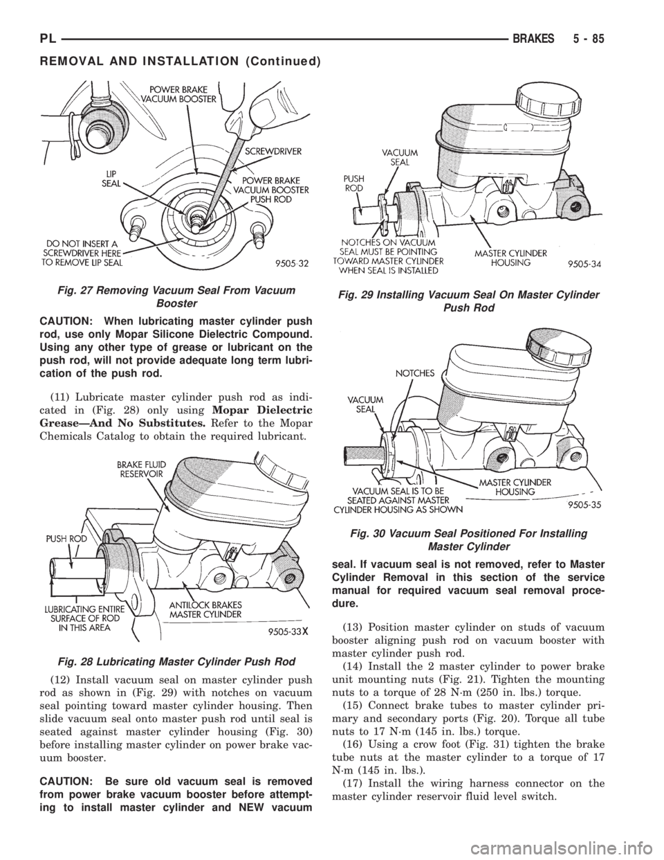
(9) Remove vacuum seal (Fig. 27) located in the
front of the power brake vacuum booster. Vacuum
seal is removed bycarefullyinserting a small screw
driver between the push rod of the power brake vac-
uum booster and vacuum seal (Fig. 27) and pry seal
out of power brake vacuum booster.Do not attempt
to pry seal out of master cylinder by inserting a
tool between seal and power brake vacuum
booster.
(10) Remove old vacuum seal from master cylinder,
if the vacuum seal came out of power brake vacuum
booster when master cylinder was removed.
CAUTION: When replacing the master cylinder on
a vehicle equipped with ABS, a NEW vacuum seal
MUST be installed in the power brake vacuum
booster. Use only the procedure detailed below for
installing vacuum seal into power brake vacuum
booster. Be sure old vacuum seal is removed from
power brake vacuum booster before attempting to
install new seal.
Fig. 24 Unlocked CAB Connector
Fig. 25 Hydraulic Control Unit Mounting Bracket
Fig. 26 Torquing Chassis Tube Nuts At HCU
5 - 84 BRAKESPL
REMOVAL AND INSTALLATION (Continued)
Page 166 of 1200
CAUTION: When lubricating master cylinder push
rod, use only Mopar Silicone Dielectric Compound.
Using any other type of grease or lubricant on the
push rod, will not provide adequate long term lubri-
cation of the push rod.
(11) Lubricate master cylinder push rod as indi-
cated in (Fig. 28) only usingMopar Dielectric
GreaseÐAnd No Substitutes.Refer to the Mopar
Chemicals Catalog to obtain the required lubricant.
(12) Install vacuum seal on master cylinder push
rod as shown in (Fig. 29) with notches on vacuum
seal pointing toward master cylinder housing. Then
slide vacuum seal onto master push rod until seal is
seated against master cylinder housing (Fig. 30)
before installing master cylinder on power brake vac-
uum booster.
CAUTION: Be sure old vacuum seal is removed
from power brake vacuum booster before attempt-
ing to install master cylinder and NEW vacuumseal. If vacuum seal is not removed, refer to Master
Cylinder Removal in this section of the service
manual for required vacuum seal removal proce-
dure.
(13) Position master cylinder on studs of vacuum
booster aligning push rod on vacuum booster with
master cylinder push rod.
(14) Install the 2 master cylinder to power brake
unit mounting nuts (Fig. 21). Tighten the mounting
nuts to a torque of 28 N´m (250 in. lbs.) torque.
(15) Connect brake tubes to master cylinder pri-
mary and secondary ports (Fig. 20). Torque all tube
nuts to 17 N´m (145 in. lbs.) torque.
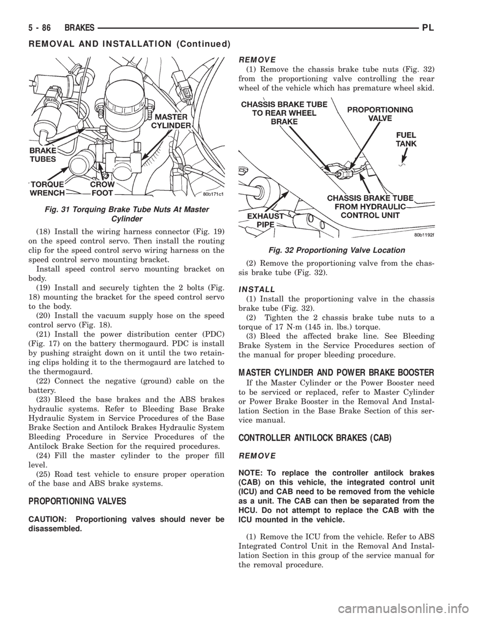
(16) Using a crow foot (Fig. 31) tighten the brake
tube nuts at the master cylinder to a torque of 17
N´m (145 in. lbs.).
(17) Install the wiring harness connector on the
master cylinder reservoir fluid level switch.
Fig. 27 Removing Vacuum Seal From Vacuum
Booster
Fig. 28 Lubricating Master Cylinder Push Rod
Fig. 29 Installing Vacuum Seal On Master Cylinder
Push Rod
Fig. 30 Vacuum Seal Positioned For Installing
Master Cylinder
PLBRAKES 5 - 85
REMOVAL AND INSTALLATION (Continued)
Page 167 of 1200
(18) Install the wiring harness connector (Fig. 19)
on the speed control servo. Then install the routing
clip for the speed control servo wiring harness on the
speed control servo mounting bracket.
Install speed control servo mounting bracket on
body.
(19) Install and securely tighten the 2 bolts (Fig.
18) mounting the bracket for the speed control servo
to the body.
(20) Install the vacuum supply hose on the speed
control servo (Fig. 18).
(21) Install the power distribution center (PDC)
(Fig. 17) on the battery thermogaurd. PDC is install
by pushing straight down on it until the two retain-
ing clips holding it to the thermogaurd are latched to
the thermogaurd.
(22) Connect the negative (ground) cable on the
battery.
(23) Bleed the base brakes and the ABS brakes
hydraulic systems. Refer to Bleeding Base Brake
Hydraulic System in Service Procedures of the Base
Brake Section and Antilock Brakes Hydraulic System
Bleeding Procedure in Service Procedures of the
Antilock Brake Section for the required procedures.
(24) Fill the master cylinder to the proper fill
level.
(25) Road test vehicle to ensure proper operation
of the base and ABS brake systems.
PROPORTIONING VALVES
CAUTION: Proportioning valves should never be
disassembled.
REMOVE
(1) Remove the chassis brake tube nuts (Fig. 32)
from the proportioning valve controlling the rear
wheel of the vehicle which has premature wheel skid.
(2) Remove the proportioning valve from the chas-
sis brake tube (Fig. 32).
INSTALL
(1) Install the proportioning valve in the chassis
brake tube (Fig. 32).
(2) Tighten the 2 chassis brake tube nuts to a
torque of 17 N´m (145 in. lbs.) torque.
(3) Bleed the affected brake line. See Bleeding
Brake System in the Service Procedures section of
the manual for proper bleeding procedure.
MASTER CYLINDER AND POWER BRAKE BOOSTER
If the Master Cylinder or the Power Booster need
to be serviced or replaced, refer to Master Cylinder
or Power Brake Booster in the Removal And Instal-
lation Section in the Base Brake Section of this ser-
vice manual.
CONTROLLER ANTILOCK BRAKES (CAB)
REMOVE
NOTE: To replace the controller antilock brakes
(CAB) on this vehicle, the integrated control unit
(ICU) and CAB need to be removed from the vehicle
as a unit. The CAB can then be separated from the
HCU. Do not attempt to replace the CAB with the
ICU mounted in the vehicle.
(1) Remove the ICU from the vehicle. Refer to ABS
Integrated Control Unit in the Removal And Instal-
lation Section in this group of the service manual for
the removal procedure.
Fig. 31 Torquing Brake Tube Nuts At Master
Cylinder
Fig. 32 Proportioning Valve Location
5 - 86 BRAKESPL
REMOVAL AND INSTALLATION (Continued)
Page 168 of 1200
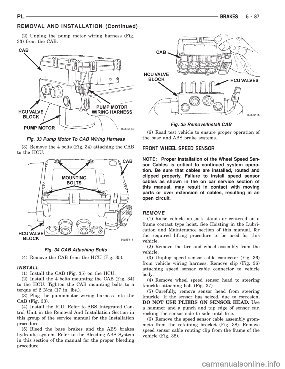
(2) Unplug the pump motor wiring harness (Fig.
33) from the CAB.
(3) Remove the 4 bolts (Fig. 34) attaching the CAB
to the HCU.
(4) Remove the CAB from the HCU (Fig. 35).
INSTALL
(1) Install the CAB (Fig. 35) on the HCU.
(2) Install the 4 bolts mounting the CAB (Fig. 34)
to the HCU. Tighten the CAB mounting bolts to a
torque of 2 N´m (17 in. lbs.).
(3) Plug the pump/motor wiring harness into the
CAB (Fig. 33).
(4) Install the ICU. Refer to ABS Integrated Con-
trol Unit in the Removal And Installation Section in
this group of the service manual for the Installation
procedure.
(5) Bleed the base brakes and the ABS brakes
hydraulic system. Refer to the Bleeding ABS System
in this section of the manual for the proper bleeding
procedure.(6) Road test vehicle to ensure proper operation of
the base and ABS brake systems.
FRONT WHEEL SPEED SENSOR
NOTE: Proper installation of the Wheel Speed Sen-
sor Cables is critical to continued system opera-
tion. Be sure that cables are installed, routed and
clipped properly. Failure to install speed sensor
cables as shown in the on car service section of
this manual, may result in contact with moving
parts or over extension of cables, resulting in an
open circuit.
REMOVE
(1) Raise vehicle on jack stands or centered on a
frame contact type hoist. See Hoisting in the Lubri-
cation and Maintenance section of this manual, for
the required lifting procedure to be used for this
vehicle.
(2) Remove the tire and wheel assembly from the
vehicle.
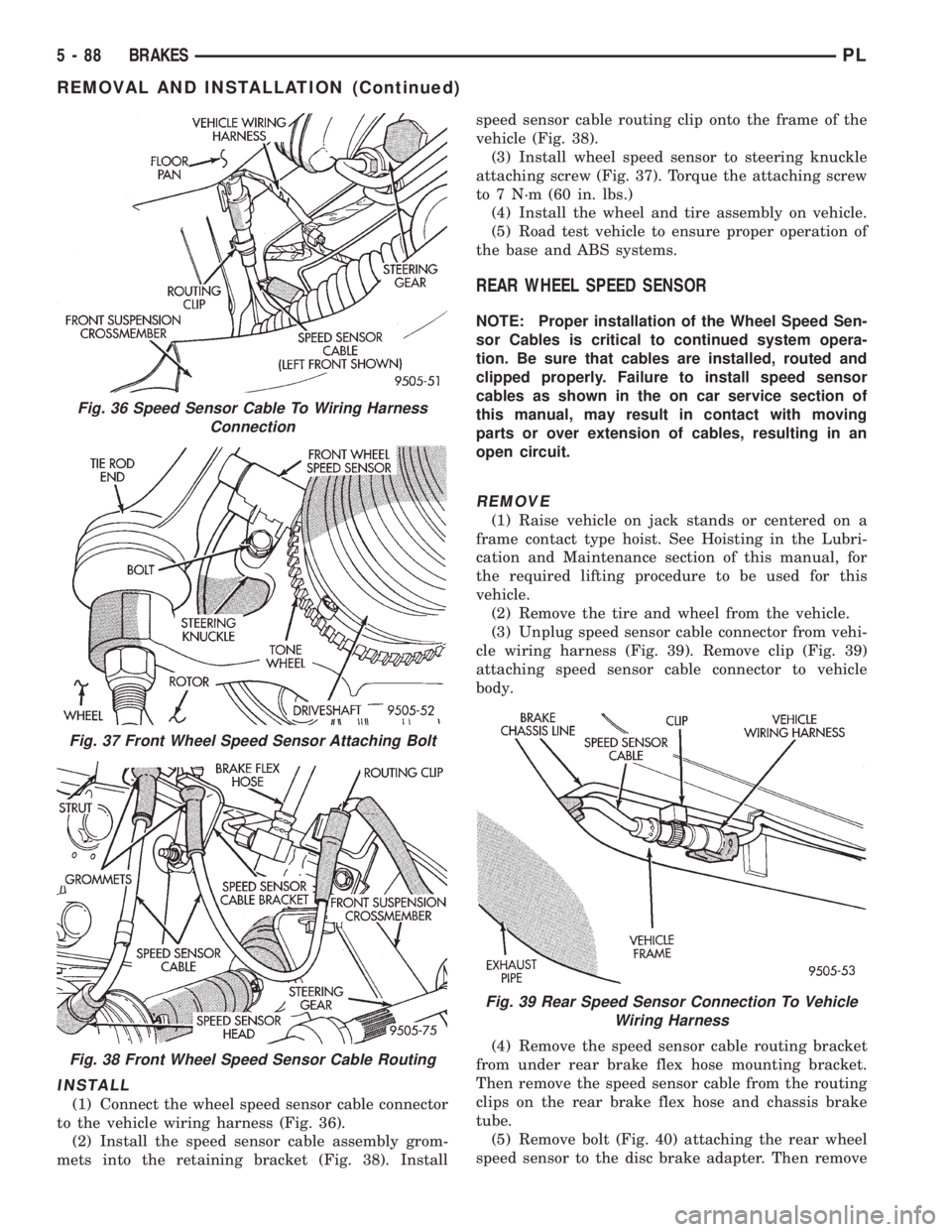
(3) Unplug speed sensor cable connector (Fig. 36)
from vehicle wiring harness. Remove clip (Fig. 36)
attaching speed sensor cable connector to vehicle
body.
(4) Remove wheel speed sensor head to steering
knuckle attaching bolt (Fig. 37).
(5) Carefully, remove sensor head from steering
knuckle. If the sensor has seized, due to corrosion,
DO NOT USE PLIERS ON SENSOR HEAD.Use
a hammer and a punch and tap edge of sensor ear,
rocking the sensor side to side until free.
(6) Remove the speed sensor cable assembly grom-
mets from the retaining bracket (Fig. 38). Remove
speed sensor cable routing clip from the frame of the
vehicle (Fig. 38).
Fig. 33 Pump Motor To CAB Wiring Harness
Fig. 34 CAB Attaching Bolts
Fig. 35 Remove/Install CAB
PLBRAKES 5 - 87
REMOVAL AND INSTALLATION (Continued)
Page 169 of 1200
INSTALL
(1) Connect the wheel speed sensor cable connector
to the vehicle wiring harness (Fig. 36).
(2) Install the speed sensor cable assembly grom-
mets into the retaining bracket (Fig. 38). Installspeed sensor cable routing clip onto the frame of the
vehicle (Fig. 38).
(3) Install wheel speed sensor to steering knuckle
attaching screw (Fig. 37). Torque the attaching screw
to 7 N´m (60 in. lbs.)
(4) Install the wheel and tire assembly on vehicle.
(5) Road test vehicle to ensure proper operation of
the base and ABS systems.
REAR WHEEL SPEED SENSOR
NOTE: Proper installation of the Wheel Speed Sen-
sor Cables is critical to continued system opera-
tion. Be sure that cables are installed, routed and
clipped properly. Failure to install speed sensor
cables as shown in the on car service section of
this manual, may result in contact with moving
parts or over extension of cables, resulting in an
open circuit.
REMOVE
(1) Raise vehicle on jack stands or centered on a
frame contact type hoist. See Hoisting in the Lubri-
cation and Maintenance section of this manual, for
the required lifting procedure to be used for this
vehicle.
(2) Remove the tire and wheel from the vehicle.
(3) Unplug speed sensor cable connector from vehi-
cle wiring harness (Fig. 39). Remove clip (Fig. 39)
attaching speed sensor cable connector to vehicle
body.
(4) Remove the speed sensor cable routing bracket
from under rear brake flex hose mounting bracket.
Then remove the speed sensor cable from the routing
clips on the rear brake flex hose and chassis brake
tube.
(5) Remove bolt (Fig. 40) attaching the rear wheel
speed sensor to the disc brake adapter. Then remove
Fig. 36 Speed Sensor Cable To Wiring Harness
Connection
Fig. 37 Front Wheel Speed Sensor Attaching Bolt
Fig. 38 Front Wheel Speed Sensor Cable Routing
Fig. 39 Rear Speed Sensor Connection To Vehicle
Wiring Harness
5 - 88 BRAKESPL
REMOVAL AND INSTALLATION (Continued)
Page 170 of 1200
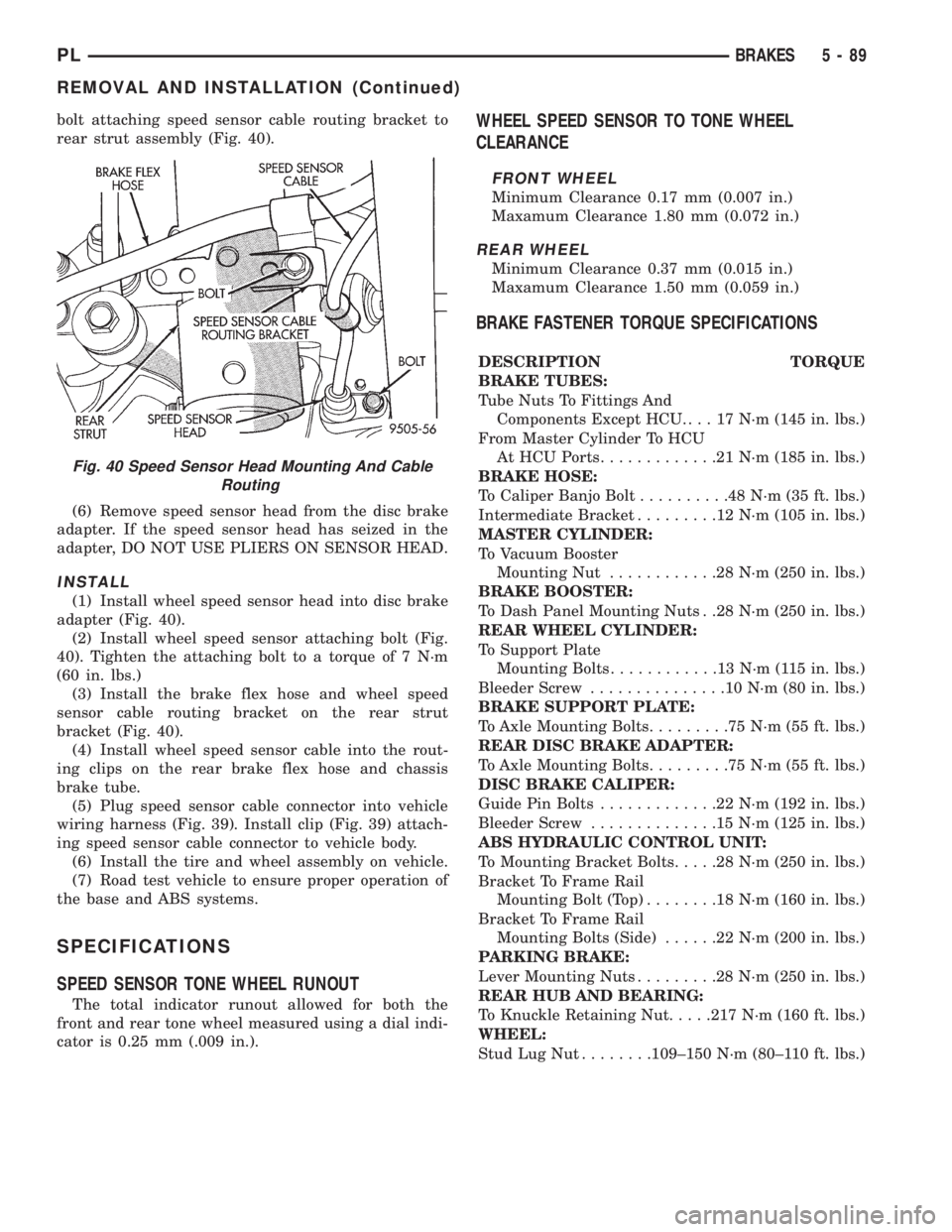
bolt attaching speed sensor cable routing bracket to
rear strut assembly (Fig. 40).
(6) Remove speed sensor head from the disc brake
adapter. If the speed sensor head has seized in the
adapter, DO NOT USE PLIERS ON SENSOR HEAD.
INSTALL
(1) Install wheel speed sensor head into disc brake
adapter (Fig. 40).
(2) Install wheel speed sensor attaching bolt (Fig.
40). Tighten the attaching bolt to a torque of 7 N´m
(60 in. lbs.)
(3) Install the brake flex hose and wheel speed
sensor cable routing bracket on the rear strut
bracket (Fig. 40).
(4) Install wheel speed sensor cable into the rout-
ing clips on the rear brake flex hose and chassis
brake tube.
(5) Plug speed sensor cable connector into vehicle
wiring harness (Fig. 39). Install clip (Fig. 39) attach-
ing speed sensor cable connector to vehicle body.
(6) Install the tire and wheel assembly on vehicle.
(7) Road test vehicle to ensure proper operation of
the base and ABS systems.
SPECIFICATIONS
SPEED SENSOR TONE WHEEL RUNOUT
The total indicator runout allowed for both the
front and rear tone wheel measured using a dial indi-
cator is 0.25 mm (.009 in.).
WHEEL SPEED SENSOR TO TONE WHEEL
CLEARANCE
FRONT WHEEL
Minimum Clearance 0.17 mm (0.007 in.)
Maxamum Clearance 1.80 mm (0.072 in.)
REAR WHEEL
Minimum Clearance 0.37 mm (0.015 in.)
Maxamum Clearance 1.50 mm (0.059 in.)
BRAKE FASTENER TORQUE SPECIFICATIONS
DESCRIPTION TORQUE
BRAKE TUBES:
Tube Nuts To Fittings And
Components Except HCU. . . . 17 N´m (145 in. lbs.)
From Master Cylinder To HCU
At HCU Ports.............21N´m(185 in. lbs.)
BRAKE HOSE:
To Caliper Banjo Bolt..........48N´m(35ft.lbs.)
Intermediate Bracket.........12N´m(105 in. lbs.)
MASTER CYLINDER:
To Vacuum Booster
Mounting Nut............28N´m(250 in. lbs.)
BRAKE BOOSTER:
To Dash Panel Mounting Nuts . .28 N´m (250 in. lbs.)
REAR WHEEL CYLINDER:
To Support Plate
Mounting Bolts............13N´m(115in.lbs.)
Bleeder Screw...............10N´m(80in.lbs.)
BRAKE SUPPORT PLATE:
To Axle Mounting Bolts.........75N´m(55ft.lbs.)
REAR DISC BRAKE ADAPTER:
To Axle Mounting Bolts.........75N´m(55ft.lbs.)
DISC BRAKE CALIPER:
Guide Pin Bolts.............22N´m(192 in. lbs.)
Bleeder Screw..............15N´m(125 in. lbs.)
ABS HYDRAULIC CONTROL UNIT:
To Mounting Bracket Bolts.....28N´m(250 in. lbs.)
Bracket To Frame Rail
Mounting Bolt (Top)........18N´m(160 in. lbs.)
Bracket To Frame Rail
Mounting Bolts (Side)......22N´m(200 in. lbs.)
PARKING BRAKE:
Lever Mounting Nuts.........28N´m(250 in. lbs.)
REAR HUB AND BEARING:
To Knuckle Retaining Nut.....217 N´m (160 ft. lbs.)
WHEEL:
Stud Lug Nut........109±150 N´m (80±110 ft. lbs.)
Fig. 40 Speed Sensor Head Mounting And Cable
Routing
PLBRAKES 5 - 89
REMOVAL AND INSTALLATION (Continued)