DODGE NEON 1999 Service Repair Manual
Manufacturer: DODGE, Model Year: 1999, Model line: NEON, Model: DODGE NEON 1999Pages: 1200, PDF Size: 35.29 MB
Page 341 of 1200
LAMP SYSTEMS
INDEX
page page
REMOVAL AND INSTALLATION
DAYTIME RUNNING LAMP (CANADA)........ 12
REMOVAL AND INSTALLATION
DAYTIME RUNNING LAMP (CANADA)
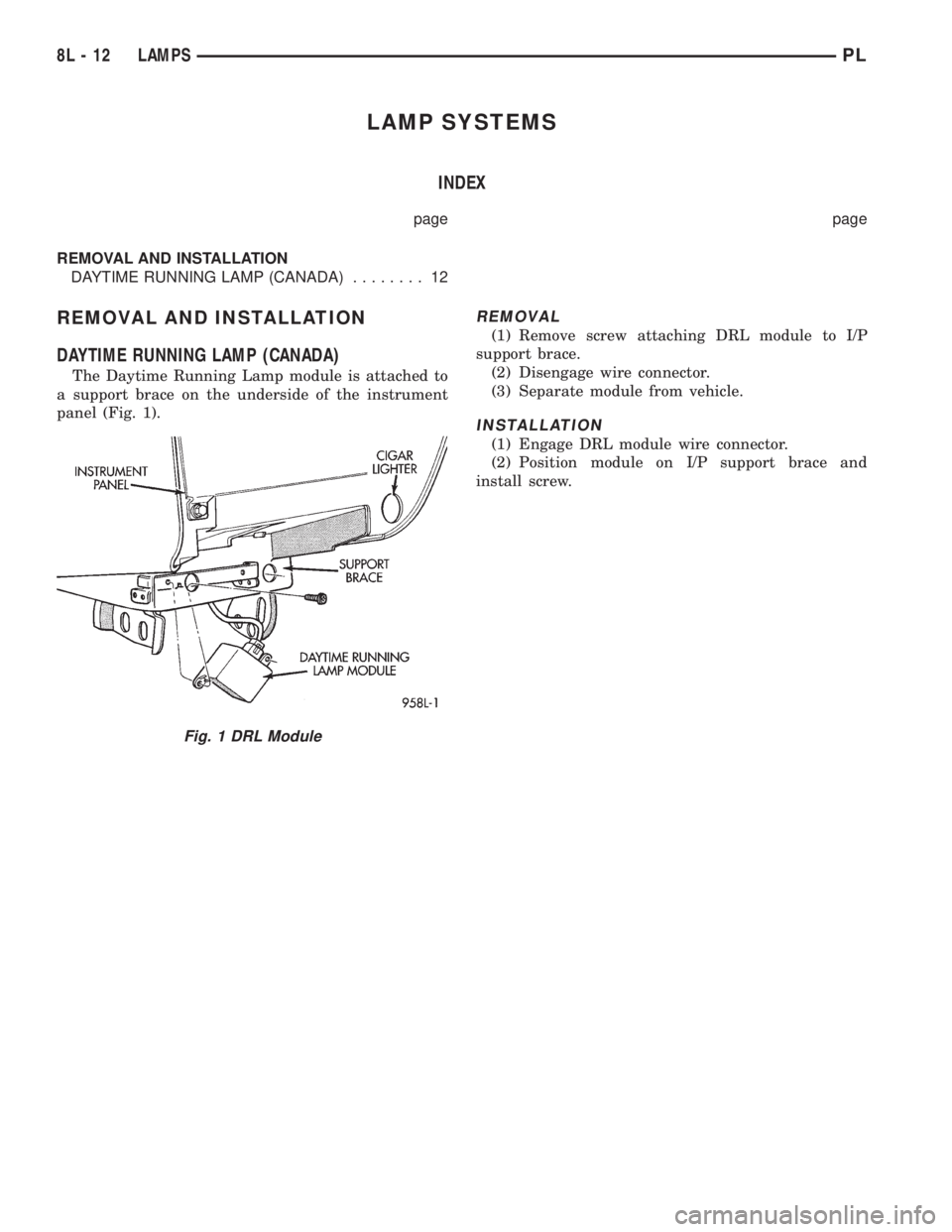
The Daytime Running Lamp module is attached to
a support brace on the underside of the instrument
panel (Fig. 1).
REMOVAL
(1) Remove screw attaching DRL module to I/P
support brace.
(2) Disengage wire connector.
(3) Separate module from vehicle.
INSTALLATION
(1) Engage DRL module wire connector.
(2) Position module on I/P support brace and
install screw.
Fig. 1 DRL Module
8L - 12 LAMPSPL
Page 342 of 1200
BULB APPLICATION
INDEX
page page
SPECIFICATIONS
EXTERIOR LAMPS....................... 13GENERAL INFORMATION................. 13
INTERIOR LAMPS....................... 13
SPECIFICATIONS
GENERAL INFORMATION
The following Bulb Application Tables lists the
lamp title on the left side of the column and trade
number or part number on the right.
CAUTION: Do not use bulbs that have a higher
candle power than the bulb listed in the Bulb Appli-
cation Table. Damage to lamp can result. Do not
touch halogen bulbs with fingers or other oily sur-
faces. Bulb life will be reduced.
EXTERIOR LAMPS
LAMP BULB
Back-up...............................3157
Center High Mounted Stop..................921
Fog.................................GE881
Headlamp..............................9007
License Plate............................168
Park/Turn Signal......................3157NA
Tail/Stop/Turn Signal.....................3157
Front Side Marker........................168
INTERIOR LAMPS
Service procedures for most of the lamps in the
instrument panel, Instrument cluster and switches
are located in Group 8E, Instrument Panel and
Gauges.
LAMP BULB
A/C and Heater Control....................203
Ash Receiver.............................161
Cigar Lighter............................203
Dome Lamp.............................578
Gear Selector Console W/Auto...............161
Glove Compartment.......................194
Ignition Lock............................161
Instrument Panel and Cluster.............PC194
Rear Cargo..............................912
Underhood..............................105
PLLAMPS 8L - 13
Page 343 of 1200

Page 344 of 1200
LAMPS
CONTENTS
page page
BULB APPLICATION....................... 8
LAMP BULB SERVICE..................... 2LAMP DIAGNOSIS........................ 1
LAMP SERVICE........................... 5
LAMP DIAGNOSIS
INDEX
page
GENERAL INFORMATION
HEADLAMP LEVELING MOTOR.............. 1
GENERAL INFORMATION
HEADLAMP LEVELING MOTOR
This vehicle is equipped with a remote headlamp
leveling system. This system allows the driver to
adjust the vertical headlamp aim from the interior ofthe vehicle to compensate for passenger or cargo
load. A headlamp leveling switch is located in the
instrument panel and controls the headlamp leveling
motor and leveling cable found mounted to the upper
radiator crossmember behind the headlamp assem-
bly.
PLLAMPS 8L - 1
Page 345 of 1200
LAMP BULB SERVICE
INDEX
page page
REMOVAL AND INSTALLATION
CITYLIGHT LAMP BULB.................... 3
FOG LAMP BULB......................... 3FRONT TURN SIGNAL LAMP BULB........... 2
HEADLAMP BULB........................ 2
SIDE REPEATER LAMP BULB............... 4
REMOVAL AND INSTALLATION
HEADLAMP BULB
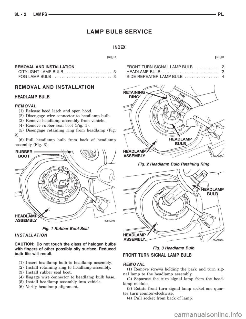
REMOVAL
(1) Release hood latch and open hood.
(2) Disengage wire connector to headlamp bulb.
(3) Remove headlamp assembly from vehicle.
(4) Remove rubber seal boot (Fig. 1).
(5) Disengage retaining ring from headlamp (Fig.
2).
(6) Pull headlamp bulb from back of headlamp
assembly (Fig. 3).
INSTALLATION
CAUTION: Do not touch the glass of halogen bulbs
with fingers of other possibly oily surface. Reduced
bulb life will result.
(1) Insert headlamp bulb to headlamp assembly.
(2) Install retaining ring to headlamp assembly.
(3) Install rubber seal boot.
(4) Engage wire connector to headlamp bulb base.
(5) Install headlamp assembly into vehicle.
(6) Verify headlamp alignment.
FRONT TURN SIGNAL LAMP BULB
REMOVAL
(1) Remove screws holding the park and turn sig-
nal lamp to the headlamp assembly.
(2) Separate the turn signal lamp from the head-
lamp module.
(3) Rotate front turn signal lamp socket one quar-
ter turn counter-clockwise.
(4) Pull socket from back of lamp.
Fig. 1 Rubber Boot Seal
Fig. 2 Headlamp Bulb Retaining Ring
Fig. 3 Headlamp Bulb
8L - 2 LAMPSPL
Page 346 of 1200
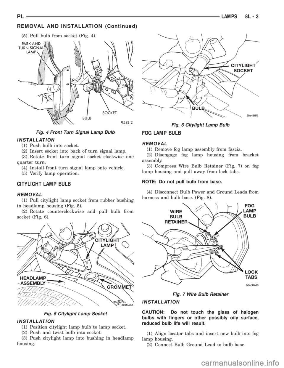
(5) Pull bulb from socket (Fig. 4).
INSTALLATION
(1) Push bulb into socket.
(2) Insert socket into back of turn signal lamp.
(3) Rotate front turn signal socket clockwise one
quarter turn.
(4) Install front turn signal lamp onto vehicle.
(5) Verify lamp operation.
CITYLIGHT LAMP BULB
REMOVAL
(1) Pull citylight lamp socket from rubber bushing
in headlamp housing (Fig. 5).
(2) Rotate counterclockwise and pull bulb from
socket (Fig. 6).
INSTALLATION
(1) Position citylight lamp bulb to lamp socket.
(2) Push and twist bulb into socket.
(3) Push citylight lamp into bushing in headlamp
housing.
FOG LAMP BULB
REMOVAL
(1) Remove fog lamp assembly from fascia.
(2) Disengage fog lamp housing from bracket
assembly.
(3) Compress Wire Bulb Retainer (Fig. 7) on fog
lamp housing and pull away from lock tabs.
NOTE: Do not pull bulb from base.
(4) Disconnect Bulb Power and Ground Leads from
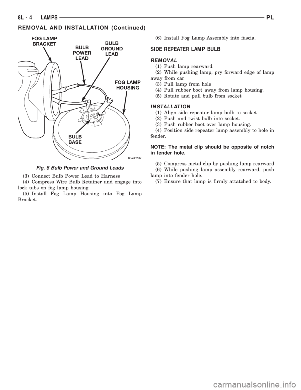
harness and bulb base. (Fig. 8).
INSTALLATION
CAUTION: Do not touch the glass of halogen
bulbs with fingers or other possibly oily surface,
reduced bulb life will result.
(1) Align locator tabs and insert new bulb into fog
lamp housing.
(2) Connect Bulb Ground Lead to bulb base.
Fig. 4 Front Turn Signal Lamp Bulb
Fig. 5 Citylight Lamp Socket
Fig. 6 Citylight Lamp Bulb
Fig. 7 Wire Bulb Retainer
PLLAMPS 8L - 3
REMOVAL AND INSTALLATION (Continued)
Page 347 of 1200
(3) Connect Bulb Power Lead to Harness
(4) Compress Wire Bulb Retainer and engage into
lock tabs on fog lamp housing
(5) Install Fog Lamp Housing into Fog Lamp
Bracket.(6) Install Fog Lamp Assembly into fascia.
SIDE REPEATER LAMP BULB
REMOVAL
(1) Push lamp rearward.
(2) While pushing lamp, pry forward edge of lamp
away from car
(3) Pull lamp from hole
(4) Pull rubber boot away from lamp housing.
(5) Rotate and pull bulb from socket
INSTALLATION
(1) Align side repeater lamp bulb to socket
(2) Push and twist bulb into socket.
(3) Push rubber boot over lamp housing.
(4) Position side repeater lamp assembly to hole in
fender.
NOTE: The metal clip should be opposite of notch
in fender hole.
(5) Compress metal clip by pushing lamp rearward
(6) While pushing lamp assembly rearward, push
lamp into fender hole.
(7) Ensure that lamp is firmly attatched to body.
Fig. 8 Bulb Power and Ground Leads
8L - 4 LAMPSPL
REMOVAL AND INSTALLATION (Continued)
Page 348 of 1200
LAMP SERVICE
INDEX
page page
GENERAL INFORMATION
HEADLAMP DIMMER SWITCH............... 5
HEADLAMP SWITCH...................... 5
REMOVAL AND INSTALLATION
FOG LAMP.............................. 6HEADLAMP ASSEMBLY.................... 5
HEADLAMP LEVELING MOTOR.............. 6
SIDE REPEATER LAMP.................... 6
GENERAL INFORMATION
HEADLAMP SWITCH
Service procedures for the headlamp switch can be
found in Group 8E, Instrument Panel and Gauges.
More information can be found in Group 8W, Wiring
Diagrams.
HEADLAMP DIMMER SWITCH
The headlamp dimmer switch is incorporated into
the multi-function (turn signal) switch. Proper proce-
dures can be found in Group 8J, Turn Signal and
Flashers. More information can be found in Group
8W, Wiring Diagrams.
REMOVAL AND INSTALLATION
HEADLAMP ASSEMBLY
REMOVAL
(1) Release hood latch and open hood.
(2) Remove headlamp horizontal aim cable from
retainer clip on radiator upper crossmember.
(3) Disengage wire connector from leveling motor.
(4) Remove bolts holding headlamp leveling motor
to the upper radiator crossmember.
(5) Remove plastic locking cap holding vertical lev-
eling cable into leveling motor arm.
(6) Separate leveling cable from motor arm.
(7) Rotate leveling cable case one quarter turn
counter-clockwise and separate cable from motor
bracket.
(8) Separate leveling motor and bracket from vehi-
cle.
(9) From between front fascia and headlamp
assembly, remove bolt holding outboard end of
assembly to fender.
(10) Remove bolts holding inboard end of assembly
to radiator closure panel.
(11) Remove bolts holding top of assembly to upper
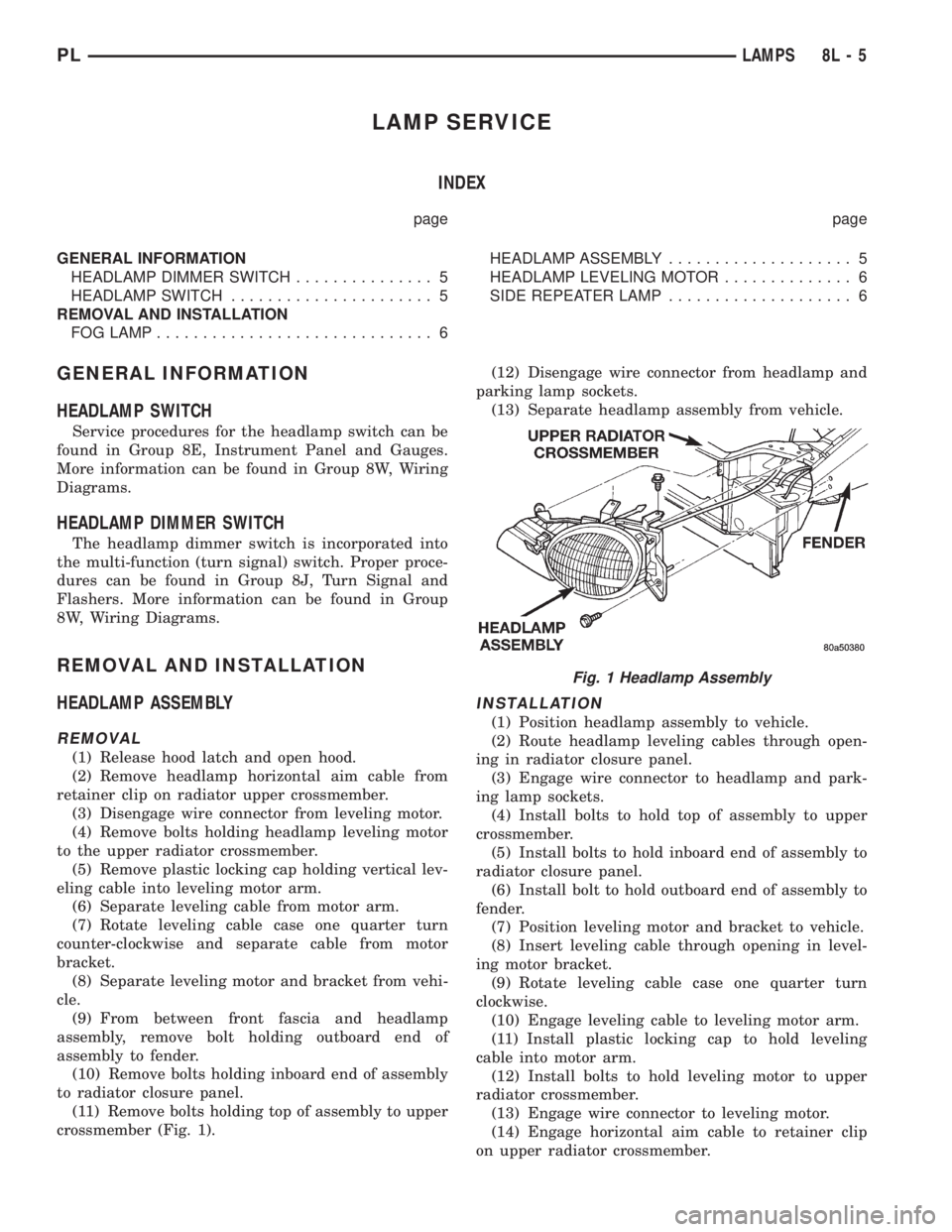
crossmember (Fig. 1).(12) Disengage wire connector from headlamp and
parking lamp sockets.
(13) Separate headlamp assembly from vehicle.
INSTALLATION
(1) Position headlamp assembly to vehicle.
(2) Route headlamp leveling cables through open-
ing in radiator closure panel.
(3) Engage wire connector to headlamp and park-
ing lamp sockets.
(4) Install bolts to hold top of assembly to upper
crossmember.
(5) Install bolts to hold inboard end of assembly to
radiator closure panel.
(6) Install bolt to hold outboard end of assembly to
fender.
(7) Position leveling motor and bracket to vehicle.
(8) Insert leveling cable through opening in level-
ing motor bracket.
(9) Rotate leveling cable case one quarter turn
clockwise.
(10) Engage leveling cable to leveling motor arm.
(11) Install plastic locking cap to hold leveling
cable into motor arm.
(12) Install bolts to hold leveling motor to upper
radiator crossmember.
(13) Engage wire connector to leveling motor.
(14) Engage horizontal aim cable to retainer clip
on upper radiator crossmember.
Fig. 1 Headlamp Assembly
PLLAMPS 8L - 5
Page 349 of 1200
(15) Verify lamp operation.
HEADLAMP LEVELING MOTOR
REMOVAL
(1) Disengage wire connector from headlamp level-
ing motor.
(2) Remove bolts holding headlamp leveling motor
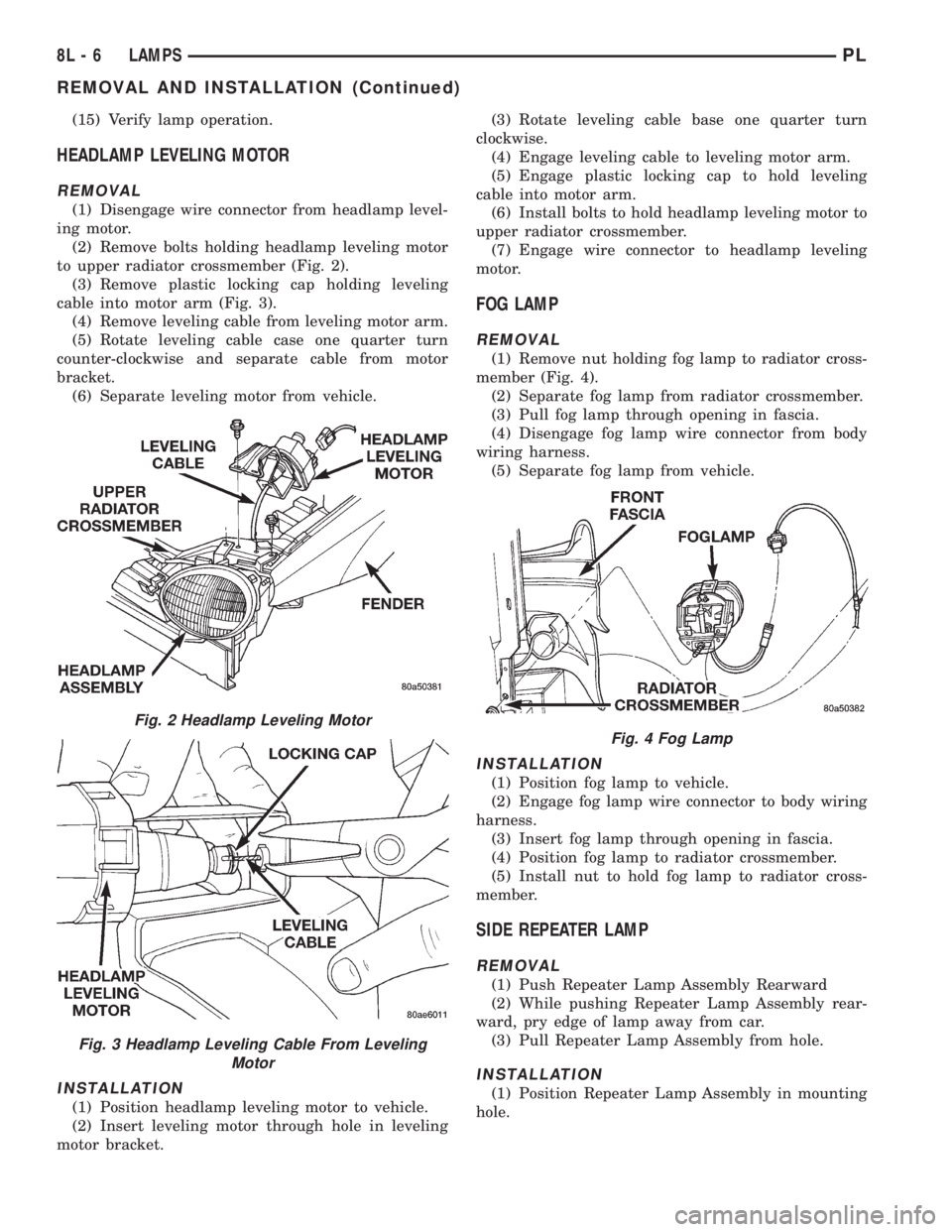
to upper radiator crossmember (Fig. 2).
(3) Remove plastic locking cap holding leveling
cable into motor arm (Fig. 3).
(4) Remove leveling cable from leveling motor arm.
(5) Rotate leveling cable case one quarter turn
counter-clockwise and separate cable from motor
bracket.
(6) Separate leveling motor from vehicle.
INSTALLATION
(1) Position headlamp leveling motor to vehicle.
(2) Insert leveling motor through hole in leveling
motor bracket.(3) Rotate leveling cable base one quarter turn
clockwise.
(4) Engage leveling cable to leveling motor arm.
(5) Engage plastic locking cap to hold leveling
cable into motor arm.
(6) Install bolts to hold headlamp leveling motor to
upper radiator crossmember.
(7) Engage wire connector to headlamp leveling
motor.
FOG LAMP
REMOVAL
(1) Remove nut holding fog lamp to radiator cross-
member (Fig. 4).
(2) Separate fog lamp from radiator crossmember.
(3) Pull fog lamp through opening in fascia.
(4) Disengage fog lamp wire connector from body
wiring harness.
(5) Separate fog lamp from vehicle.
INSTALLATION
(1) Position fog lamp to vehicle.
(2) Engage fog lamp wire connector to body wiring
harness.
(3) Insert fog lamp through opening in fascia.
(4) Position fog lamp to radiator crossmember.
(5) Install nut to hold fog lamp to radiator cross-
member.
SIDE REPEATER LAMP
REMOVAL
(1) Push Repeater Lamp Assembly Rearward
(2) While pushing Repeater Lamp Assembly rear-
ward, pry edge of lamp away from car.
(3) Pull Repeater Lamp Assembly from hole.
INSTALLATION
(1) Position Repeater Lamp Assembly in mounting
hole.
Fig. 2 Headlamp Leveling Motor
Fig. 3 Headlamp Leveling Cable From Leveling
Motor
Fig. 4 Fog Lamp
8L - 6 LAMPSPL
REMOVAL AND INSTALLATION (Continued)
Page 350 of 1200
NOTE: The metal clip on the Repeater Lamp
Assembly should be opposite from notch in fender
hole.
(2) Compress metal clip by pushing Repeater
Lamp Assembly rearward.(3) While pushing Repeater Lamp Assembly rear-
ward, push lamp into fender hole.
(4) Ensure that Repeater Lamp Assembly is firmly
attatched to body.
PLLAMPS 8L - 7
REMOVAL AND INSTALLATION (Continued)