DODGE RAM 2001 Service Repair Manual
Manufacturer: DODGE, Model Year: 2001, Model line: RAM, Model: DODGE RAM 2001Pages: 2889, PDF Size: 68.07 MB
Page 281 of 2889
(4) Have helper press and hold brake pedal to floor
and observe warning light.
(a) If warning light illuminates, switch is operat-
ing correctly.
(b) If light fails to illuminate, check circuit fuse,
bulb, and wiring. The parking brake switch can be
used to aid in identifying whether or not the brake
light bulb and fuse is functional. Repair or replace
parts as necessary and test differential pressure
switch operation again.
(5) If warning light still does not illuminate,
switch is faulty. Replace combination valve assembly,
bleed brake system and verify proper switch and
valve operation.
REMOVAL
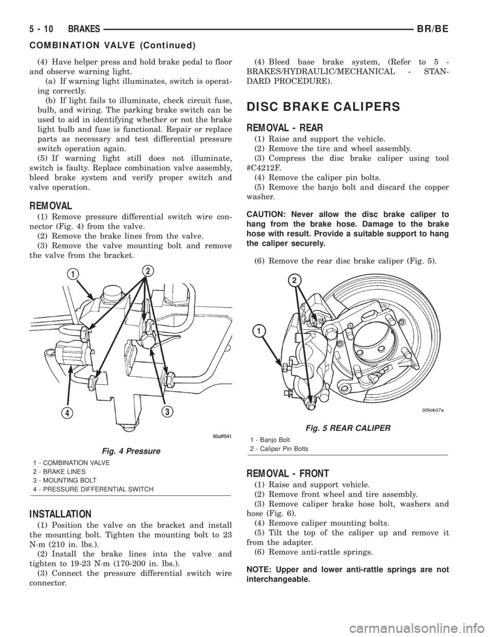
(1) Remove pressure differential switch wire con-
nector (Fig. 4) from the valve.
(2) Remove the brake lines from the valve.
(3) Remove the valve mounting bolt and remove
the valve from the bracket.
INSTALLATION
(1) Position the valve on the bracket and install
the mounting bolt. Tighten the mounting bolt to 23
N´m (210 in. lbs.).
(2) Install the brake lines into the valve and
tighten to 19-23 N´m (170-200 in. lbs.).
(3) Connect the pressure differential switch wire
connector.(4) Bleed base brake system, (Refer to 5 -
BRAKES/HYDRAULIC/MECHANICAL - STAN-
DARD PROCEDURE).
DISC BRAKE CALIPERS
REMOVAL - REAR
(1) Raise and support the vehicle.
(2) Remove the tire and wheel assembly.
(3) Compress the disc brake caliper using tool
#C4212F.
(4) Remove the caliper pin bolts.
(5) Remove the banjo bolt and discard the copper
washer.
CAUTION: Never allow the disc brake caliper to
hang from the brake hose. Damage to the brake
hose with result. Provide a suitable support to hang
the caliper securely.
(6) Remove the rear disc brake caliper (Fig. 5).
REMOVAL - FRONT
(1) Raise and support vehicle.
(2) Remove front wheel and tire assembly.
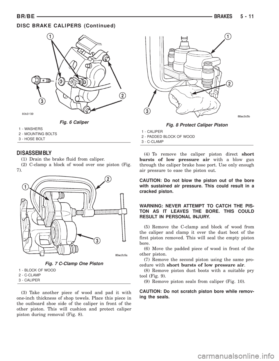
(3) Remove caliper brake hose bolt, washers and
hose (Fig. 6).
(4) Remove caliper mounting bolts.
(5) Tilt the top of the caliper up and remove it
from the adapter.
(6) Remove anti-rattle springs.
NOTE: Upper and lower anti-rattle springs are not
interchangeable.
Fig. 4 Pressure
1 - COMBINATION VALVE
2 - BRAKE LINES
3 - MOUNTING BOLT
4 - PRESSURE DIFFERENTIAL SWITCH
Fig. 5 REAR CALIPER
1 - Banjo Bolt
2 - Caliper Pin Bolts
5 - 10 BRAKESBR/BE
COMBINATION VALVE (Continued)
Page 282 of 2889
DISASSEMBLY
(1) Drain the brake fluid from caliper.
(2) C-clamp a block of wood over one piston (Fig.
7).
(3) Take another piece of wood and pad it with
one-inch thickness of shop towels. Place this piece in
the outboard shoe side of the caliper in front of the
other piston. This will cushion and protect caliper
piston during removal (Fig. 8).(4) To remove the caliper piston directshort
bursts of low pressure airwith a blow gun
through the caliper brake hose port. Use only enough
air pressure to ease the piston out.
CAUTION: Do not blow the piston out of the bore
with sustained air pressure. This could result in a
cracked piston.
WARNING: NEVER ATTEMPT TO CATCH THE PIS-
TON AS IT LEAVES THE BORE. THIS COULD
RESULT IN PERSONAL INJURY.
(5) Remove the C-clamp and block of wood from
the caliper and clamp it over the dust boot of the
first piston removed. This will seal the empty piston
bore.
(6) Move the padded piece of wood in front of the
other piston.
(7) Remove the second piston using the same pro-
cedure withshort bursts of low pressure air.
(8) Remove piston dust boots with a suitable pry
tool (Fig. 9).
(9) Remove piston seals from caliper (Fig. 10).
CAUTION: Do not scratch piston bore while remov-
ing the seals.
Fig. 6 Caliper
1 - WASHERS
2 - MOUNTING BOLTS
3 - HOSE BOLT
Fig. 7 C-Clamp One Piston
1 - BLOCK OF WOOD
2 - C-CLAMP
3 - CALIPER
Fig. 8 Protect Caliper Piston
1 - CALIPER
2 - PADDED BLOCK OF WOOD
3 - C-CLAMP
BR/BEBRAKES 5 - 11
DISC BRAKE CALIPERS (Continued)
Page 283 of 2889
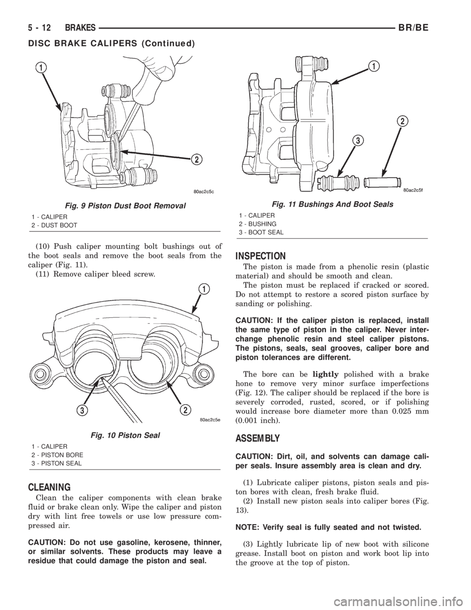
(10) Push caliper mounting bolt bushings out of
the boot seals and remove the boot seals from the
caliper (Fig. 11).
(11) Remove caliper bleed screw.
CLEANING
Clean the caliper components with clean brake
fluid or brake clean only. Wipe the caliper and piston
dry with lint free towels or use low pressure com-
pressed air.
CAUTION: Do not use gasoline, kerosene, thinner,
or similar solvents. These products may leave a
residue that could damage the piston and seal.
INSPECTION
The piston is made from a phenolic resin (plastic
material) and should be smooth and clean.
The piston must be replaced if cracked or scored.
Do not attempt to restore a scored piston surface by
sanding or polishing.
CAUTION: If the caliper piston is replaced, install
the same type of piston in the caliper. Never inter-
change phenolic resin and steel caliper pistons.
The pistons, seals, seal grooves, caliper bore and
piston tolerances are different.
The bore can belightlypolished with a brake
hone to remove very minor surface imperfections
(Fig. 12). The caliper should be replaced if the bore is
severely corroded, rusted, scored, or if polishing
would increase bore diameter more than 0.025 mm
(0.001 inch).
ASSEMBLY
CAUTION: Dirt, oil, and solvents can damage cali-
per seals. Insure assembly area is clean and dry.
(1) Lubricate caliper pistons, piston seals and pis-
ton bores with clean, fresh brake fluid.
(2) Install new piston seals into caliper bores (Fig.
13).
NOTE: Verify seal is fully seated and not twisted.
(3) Lightly lubricate lip of new boot with silicone
grease. Install boot on piston and work boot lip into
the groove at the top of piston.
Fig. 9 Piston Dust Boot Removal
1 - CALIPER
2 - DUST BOOT
Fig. 10 Piston Seal
1 - CALIPER
2 - PISTON BORE
3 - PISTON SEAL
Fig. 11 Bushings And Boot Seals
1 - CALIPER
2 - BUSHING
3 - BOOT SEAL
5 - 12 BRAKESBR/BE
DISC BRAKE CALIPERS (Continued)
Page 284 of 2889
(4) Stretch boot rearward to straighten boot folds,
then move boot forward until folds snap into place.
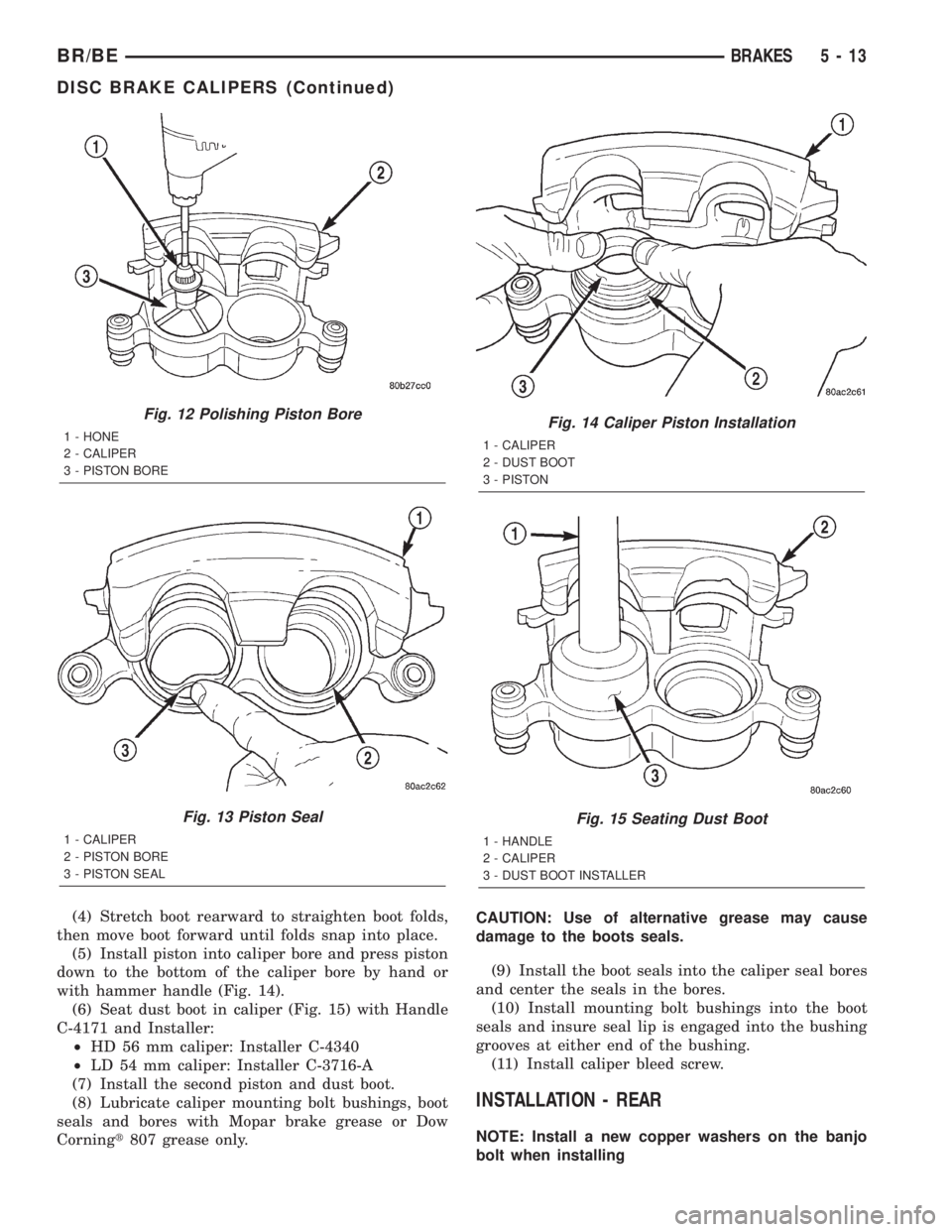
(5) Install piston into caliper bore and press piston
down to the bottom of the caliper bore by hand or
with hammer handle (Fig. 14).
(6) Seat dust boot in caliper (Fig. 15) with Handle
C-4171 and Installer:
²HD 56 mm caliper: Installer C-4340
²LD 54 mm caliper: Installer C-3716-A
(7) Install the second piston and dust boot.
(8) Lubricate caliper mounting bolt bushings, boot
seals and bores with Mopar brake grease or Dow
Corningt807 grease only.CAUTION: Use of alternative grease may cause
damage to the boots seals.
(9) Install the boot seals into the caliper seal bores
and center the seals in the bores.
(10) Install mounting bolt bushings into the boot
seals and insure seal lip is engaged into the bushing
grooves at either end of the bushing.
(11) Install caliper bleed screw.
INSTALLATION - REAR
NOTE: Install a new copper washers on the banjo
bolt when installing
Fig. 12 Polishing Piston Bore
1 - HONE
2 - CALIPER
3 - PISTON BORE
Fig. 13 Piston Seal
1 - CALIPER
2 - PISTON BORE
3 - PISTON SEAL
Fig. 14 Caliper Piston Installation
1 - CALIPER
2 - DUST BOOT
3 - PISTON
Fig. 15 Seating Dust Boot
1 - HANDLE
2 - CALIPER
3 - DUST BOOT INSTALLER
BR/BEBRAKES 5 - 13
DISC BRAKE CALIPERS (Continued)
Page 285 of 2889
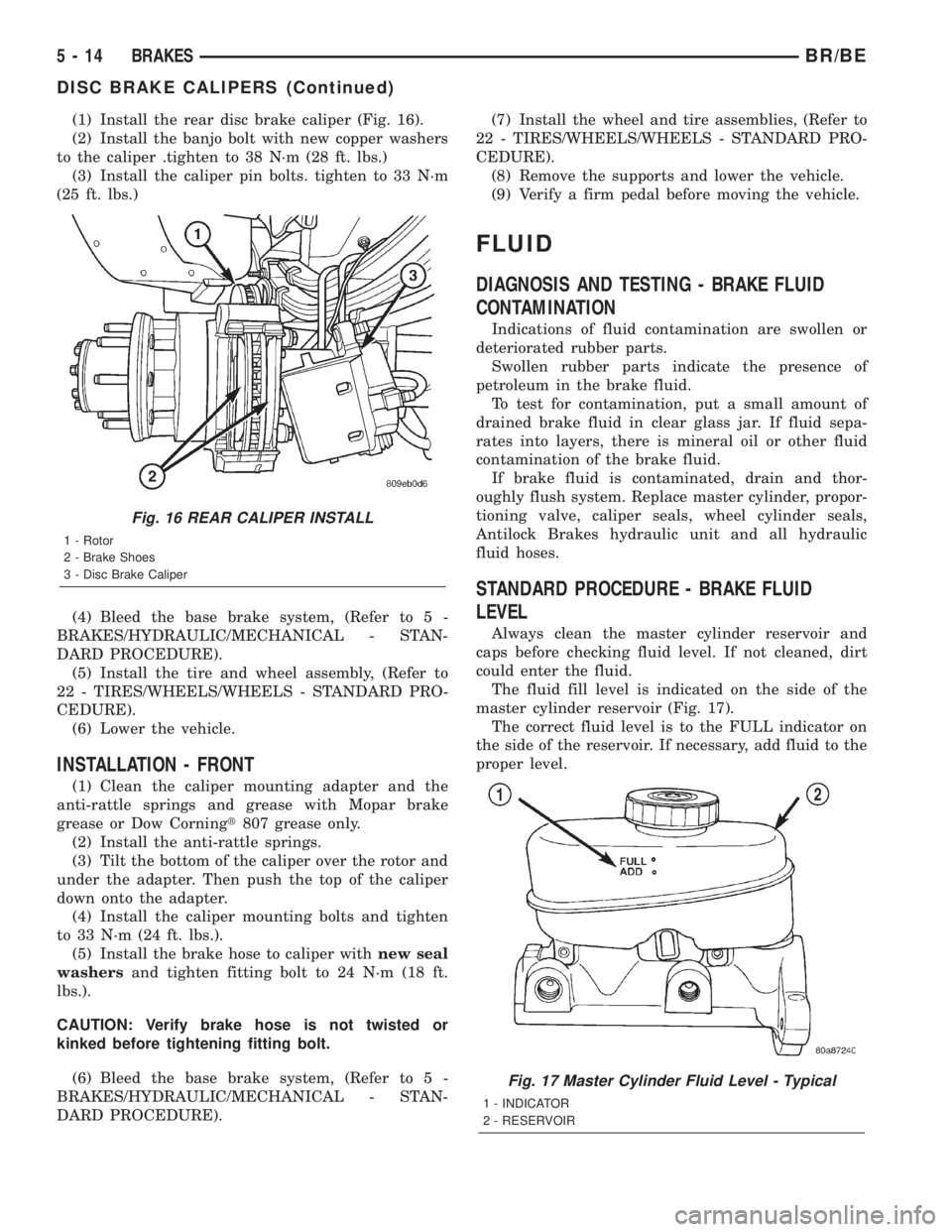
(1) Install the rear disc brake caliper (Fig. 16).
(2) Install the banjo bolt with new copper washers
to the caliper .tighten to 38 N´m (28 ft. lbs.)
(3) Install the caliper pin bolts. tighten to 33 N´m
(25 ft. lbs.)
(4) Bleed the base brake system, (Refer to 5 -
BRAKES/HYDRAULIC/MECHANICAL - STAN-
DARD PROCEDURE).
(5) Install the tire and wheel assembly, (Refer to
22 - TIRES/WHEELS/WHEELS - STANDARD PRO-
CEDURE).
(6) Lower the vehicle.
INSTALLATION - FRONT
(1) Clean the caliper mounting adapter and the
anti-rattle springs and grease with Mopar brake
grease or Dow Corningt807 grease only.
(2) Install the anti-rattle springs.
(3) Tilt the bottom of the caliper over the rotor and
under the adapter. Then push the top of the caliper
down onto the adapter.
(4) Install the caliper mounting bolts and tighten
to 33 N´m (24 ft. lbs.).
(5) Install the brake hose to caliper withnew seal
washersand tighten fitting bolt to 24 N´m (18 ft.
lbs.).
CAUTION: Verify brake hose is not twisted or
kinked before tightening fitting bolt.
(6) Bleed the base brake system, (Refer to 5 -
BRAKES/HYDRAULIC/MECHANICAL - STAN-
DARD PROCEDURE).(7) Install the wheel and tire assemblies, (Refer to
22 - TIRES/WHEELS/WHEELS - STANDARD PRO-
CEDURE).
(8) Remove the supports and lower the vehicle.
(9) Verify a firm pedal before moving the vehicle.
FLUID
DIAGNOSIS AND TESTING - BRAKE FLUID
CONTAMINATION
Indications of fluid contamination are swollen or
deteriorated rubber parts.
Swollen rubber parts indicate the presence of
petroleum in the brake fluid.
To test for contamination, put a small amount of
drained brake fluid in clear glass jar. If fluid sepa-
rates into layers, there is mineral oil or other fluid
contamination of the brake fluid.
If brake fluid is contaminated, drain and thor-
oughly flush system. Replace master cylinder, propor-
tioning valve, caliper seals, wheel cylinder seals,
Antilock Brakes hydraulic unit and all hydraulic
fluid hoses.
STANDARD PROCEDURE - BRAKE FLUID
LEVEL
Always clean the master cylinder reservoir and
caps before checking fluid level. If not cleaned, dirt
could enter the fluid.
The fluid fill level is indicated on the side of the
master cylinder reservoir (Fig. 17).
The correct fluid level is to the FULL indicator on
the side of the reservoir. If necessary, add fluid to the
proper level.
Fig. 16 REAR CALIPER INSTALL
1 - Rotor
2 - Brake Shoes
3 - Disc Brake Caliper
Fig. 17 Master Cylinder Fluid Level - Typical
1 - INDICATOR
2 - RESERVOIR
5 - 14 BRAKESBR/BE
DISC BRAKE CALIPERS (Continued)
Page 286 of 2889
SPECIFICATIONS
BRAKE FLUID
The brake fluid used in this vehicle must conform
to DOT 3 specifications and SAE J1703 standards.
No other type of brake fluid is recommended or
approved for usage in the vehicle brake system. Use
only Mopar brake fluid or an equivalent from a
tightly sealed container.
CAUTION: Never use reclaimed brake fluid or fluid
from an container which has been left open. An
open container of brake fluid will absorb moisture
from the air and contaminate the fluid.
CAUTION: Never use any type of a petroleum-based
fluid in the brake hydraulic system. Use of such
type fluids will result in seal damage of the vehicle
brake hydraulic system causing a failure of the
vehicle brake system. Petroleum based fluids would
be items such as engine oil, transmission fluid,
power steering fluid, etc.
FLUID RESERVOIR
REMOVAL
(1) Remove reservoir cap and empty fluid into
drain container.
(2) Clamp cylinder body in vise with brass protec-
tive jaws.
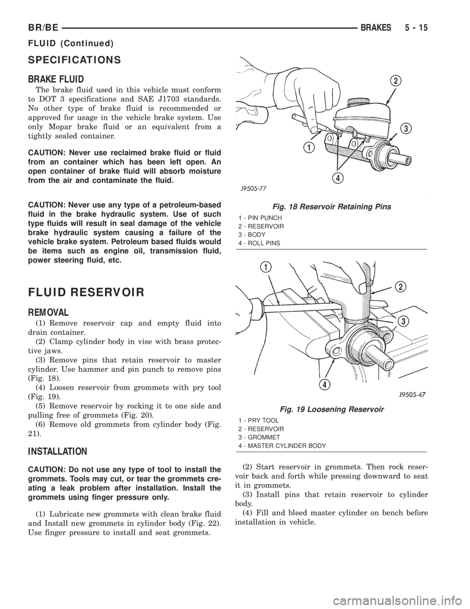
(3) Remove pins that retain reservoir to master
cylinder. Use hammer and pin punch to remove pins
(Fig. 18).
(4) Loosen reservoir from grommets with pry tool
(Fig. 19).
(5) Remove reservoir by rocking it to one side and
pulling free of grommets (Fig. 20).
(6) Remove old grommets from cylinder body (Fig.
21).
INSTALLATION
CAUTION: Do not use any type of tool to install the
grommets. Tools may cut, or tear the grommets cre-
ating a leak problem after installation. Install the
grommets using finger pressure only.
(1) Lubricate new grommets with clean brake fluid
and Install new grommets in cylinder body (Fig. 22).
Use finger pressure to install and seat grommets.(2) Start reservoir in grommets. Then rock reser-
voir back and forth while pressing downward to seat
it in grommets.
(3) Install pins that retain reservoir to cylinder
body.
(4) Fill and bleed master cylinder on bench before
installation in vehicle.
Fig. 18 Reservoir Retaining Pins
1 - PIN PUNCH
2 - RESERVOIR
3 - BODY
4 - ROLL PINS
Fig. 19 Loosening Reservoir
1-PRYTOOL
2 - RESERVOIR
3 - GROMMET
4 - MASTER CYLINDER BODY
BR/BEBRAKES 5 - 15
FLUID (Continued)
Page 287 of 2889
PEDAL
DESCRIPTION
The brake booster is operated by a suspended type
brake pedal. The pedal pivots on a shaft located in a
mounting bracket attached to the dash panel. The
pedal shaft is supported by bushings in the pedal
and mounting bracket. The brake pedal is attached
to the booster push rod.
OPERATION
When the pedal is depressed, the primary booster
push rod is depressed which move the booster sec-
ondary rod. The booster secondary rod depress the
master cylinder piston.
REMOVAL
(1) Remove knee bolster, (Refer to 23 - BODY/IN-
STRUMENT PANEL/STEERING COLUMN OPEN-
ING COVER - REMOVAL).
(2) Remove brake lamp switch, (Refer to 8 - ELEC-
TRICAL/LAMPS/LIGHTING - EXTERIOR/BRAKE
LAMP SWITCH - REMOVAL).
(3) Remove switches from tabs on brake lamp
switch bracket.
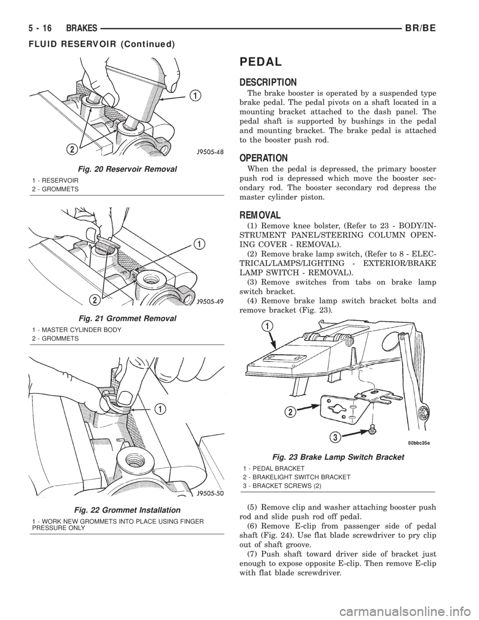
(4) Remove brake lamp switch bracket bolts and
remove bracket (Fig. 23).
(5) Remove clip and washer attaching booster push
rod and slide push rod off pedal.
(6) Remove E-clip from passenger side of pedal
shaft (Fig. 24). Use flat blade screwdriver to pry clip
out of shaft groove.
(7) Push shaft toward driver side of bracket just
enough to expose opposite E-clip. Then remove E-clip
with flat blade screwdriver.
Fig. 20 Reservoir Removal
1 - RESERVOIR
2 - GROMMETS
Fig. 21 Grommet Removal
1 - MASTER CYLINDER BODY
2 - GROMMETS
Fig. 22 Grommet Installation
1 - WORK NEW GROMMETS INTO PLACE USING FINGER
PRESSURE ONLY
Fig. 23 Brake Lamp Switch Bracket
1 - PEDAL BRACKET
2 - BRAKELIGHT SWITCH BRACKET
3 - BRACKET SCREWS (2)
5 - 16 BRAKESBR/BE
FLUID RESERVOIR (Continued)
Page 288 of 2889
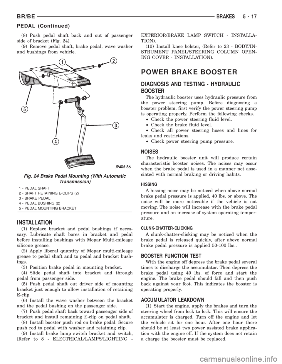
(8) Push pedal shaft back and out of passenger
side of bracket (Fig. 24).
(9) Remove pedal shaft, brake pedal, wave washer
and bushings from vehicle.
INSTALLATION
(1) Replace bracket and pedal bushings if neces-
sary. Lubricate shaft bores in bracket and pedal
before installing bushings with Mopar Multi-mileage
silicone grease.
(2) Apply liberal quantity of Mopar multi-mileage
grease to pedal shaft and to pedal and bracket bush-
ings.
(3) Position brake pedal in mounting bracket.
(4) Slide pedal shaft into bracket and through
pedal from passenger side.
(5) Push pedal shaft out driver side of mounting
bracket just enough to allow installation of retaining
E-clip.
(6) Install the wave washer between the bracket
and the pedal bushing on the passenger side.
(7) Push pedal shaft back toward passenger side of
bracket and install remaining E-clip on pedal shaft.
(8) Install booster push rod on brake pedal. Secure
push rod to pedal with washer and retaining clip.
(9) Install brake lamp switch bracket and switch,
(Refer to 8 - ELECTRICAL/LAMPS/LIGHTING -EXTERIOR/BRAKE LAMP SWITCH - INSTALLA-
TION).
(10) Install knee bolster, (Refer to 23 - BODY/IN-
STRUMENT PANEL/STEERING COLUMN OPEN-
ING COVER - INSTALLATION).
POWER BRAKE BOOSTER
DIAGNOSIS AND TESTING - HYDRAULIC
BOOSTER
The hydraulic booster uses hydraulic pressure from
the power steering pump. Before diagnosing a
booster problem, first verify the power steering pump
is operating properly. Perform the following checks.
²Check the power steering fluid level.
²Check the brake fluid level.
²Check all power steering hoses and lines for
leaks and restrictions.
²Check power steering pump pressure.
NOISES
The hydraulic booster unit will produce certain
characteristic booster noises. The noises may occur
when the brake pedal is used in a manner not asso-
ciated with normal braking or driving habits.
HISSING
A hissing noise may be noticed when above normal
brake pedal pressure is applied, 40 lbs. or above. The
noise will be more noticeable if the vehicle is not
moving. The noise will increase with the brake pedal
pressure and an increase of system operating temper-
ature.
CLUNK-CHATTER-CLICKING
A clunk-chatter-clicking may be noticed when the
brake pedal is released quickly, after above normal
brake pedal pressure is applied 50-100 lbs..
BOOSTER FUNCTION TEST
With the engine off depress the brake pedal several
times to discharge the accumulator. Then depress the
brake pedal using 40 lbs. of force and start the
engine. The brake pedal should fall and then push
back against your foot. This indicates the booster is
operating properly.
ACCUMULATOR LEAKDOWN
(1) Start the engine, apply the brakes and turn the
steering wheel from lock to lock. This will ensure the
accumulator is charged. Turn off the engine and let
the vehicle sit for one hour. After one hour there
should be at least two power assisted brake applica-
tion with the engine off. If the system does not retain
a charge the booster must be replaced.
Fig. 24 Brake Pedal Mounting (With Automatic
Transmission)
1 - PEDAL SHAFT
2 - SHAFT RETAINING E-CLIPS (2)
3 - BRAKE PEDAL
4 - PEDAL BUSHING (2)
5 - PEDAL MOUNTING BRACKET
BR/BEBRAKES 5 - 17
PEDAL (Continued)
Page 289 of 2889
(2) With the engine off depress the brake pedal
several times to discharge the accumulator. Grasp
the accumulator and see if it wobbles or turns. If it
does the accumulator has lost a gas charge and the
booster must be replaced.
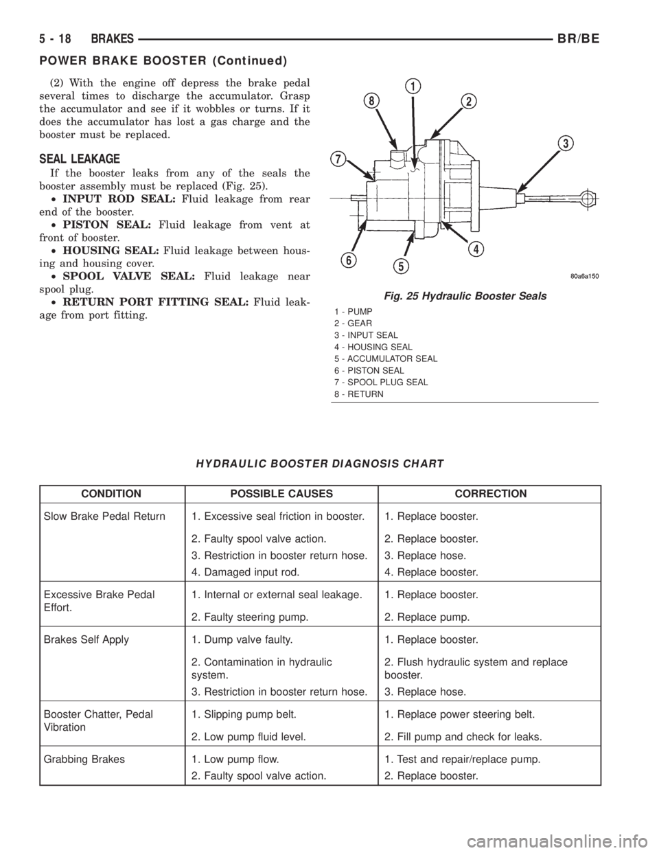
SEAL LEAKAGE
If the booster leaks from any of the seals the
booster assembly must be replaced (Fig. 25).
²INPUT ROD SEAL:Fluid leakage from rear
end of the booster.
²PISTON SEAL:Fluid leakage from vent at
front of booster.
²HOUSING SEAL:Fluid leakage between hous-
ing and housing cover.
²SPOOL VALVE SEAL:Fluid leakage near
spool plug.
²RETURN PORT FITTING SEAL:Fluid leak-
age from port fitting.
HYDRAULIC BOOSTER DIAGNOSIS CHART
CONDITION POSSIBLE CAUSES CORRECTION
Slow Brake Pedal Return 1. Excessive seal friction in booster. 1. Replace booster.
2. Faulty spool valve action. 2. Replace booster.
3. Restriction in booster return hose. 3. Replace hose.
4. Damaged input rod. 4. Replace booster.
Excessive Brake Pedal
Effort.1. Internal or external seal leakage. 1. Replace booster.
2. Faulty steering pump. 2. Replace pump.
Brakes Self Apply 1. Dump valve faulty. 1. Replace booster.
2. Contamination in hydraulic
system.2. Flush hydraulic system and replace
booster.
3. Restriction in booster return hose. 3. Replace hose.
Booster Chatter, Pedal
Vibration1. Slipping pump belt. 1. Replace power steering belt.
2. Low pump fluid level. 2. Fill pump and check for leaks.
Grabbing Brakes 1. Low pump flow. 1. Test and repair/replace pump.
2. Faulty spool valve action. 2. Replace booster.
Fig. 25 Hydraulic Booster Seals
1 - PUMP
2 - GEAR
3 - INPUT SEAL
4 - HOUSING SEAL
5 - ACCUMULATOR SEAL
6 - PISTON SEAL
7 - SPOOL PLUG SEAL
8 - RETURN
5 - 18 BRAKESBR/BE
POWER BRAKE BOOSTER (Continued)
Page 290 of 2889
STANDARD PROCEDURE - BLEEDING
The hydraulic booster is generally self-bleeding,
this procedure will normally bleed the air from the
booster. Normal driving and operation of the unit will
remove any remaining trapped air.
(1) Fill power steering pump reservoir.
(2) Disconnect fuel shutdown relay and crank the
engine for several seconds, Refer to Fuel System for
relay location and WARNING.
(3) Check fluid level and add if necessary.
(4) Connect fuel shutdown relay and start the
engine.
(5) Turn the steering wheel slowly from lock to
lock twice.
(6) Stop the engine and discharge the accumulator
by depressing the brake pedal 5 times.
(7) Start the engine and turn the steering wheel
slowly from lock to lock twice.
(8) Turn off the engine and check fluid level and
add if necessary.
NOTE: If fluid foaming occurs, wait for foam to dis-
sipate and repeat steps 7 and 8.
REMOVAL
NOTE: If the booster is being replaced because the
power steering fluid is contaminated, flush the
power steering system before replacing the booster.
(1) With engine off depress the brake pedal 5
times to discharge the accumulator.
(2) Remove brake lines from master cylinder.
(3) Remove mounting nuts from the master cylin-
der.
(4) Remove the bracket from the hydraulic booster
lines and master cylinder mounting studs.
(5) Remove the master cylinder.
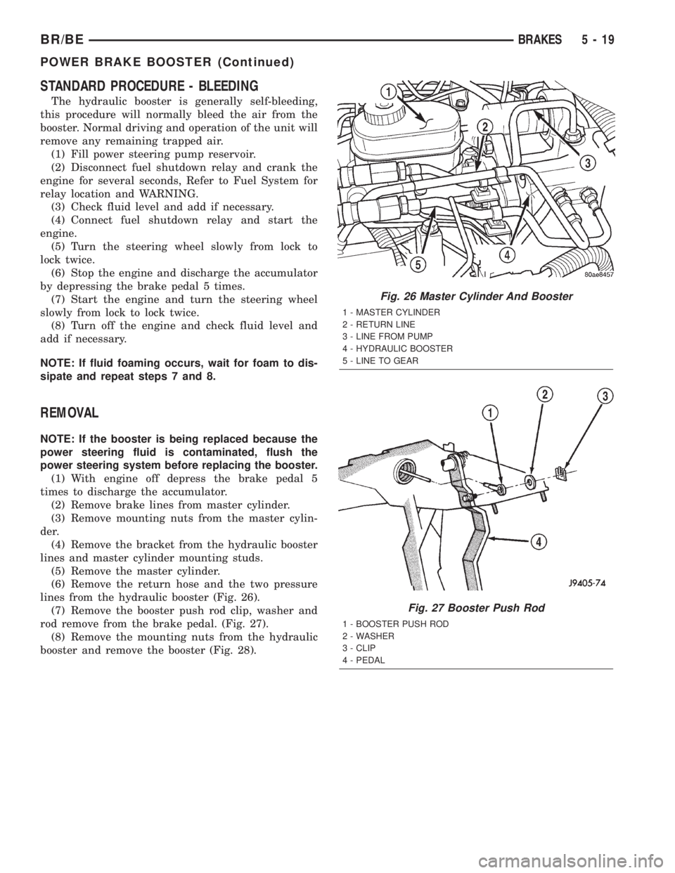
(6) Remove the return hose and the two pressure
lines from the hydraulic booster (Fig. 26).
(7) Remove the booster push rod clip, washer and
rod remove from the brake pedal. (Fig. 27).
(8) Remove the mounting nuts from the hydraulic
booster and remove the booster (Fig. 28).
Fig. 26 Master Cylinder And Booster
1 - MASTER CYLINDER
2 - RETURN LINE
3 - LINE FROM PUMP
4 - HYDRAULIC BOOSTER
5 - LINE TO GEAR
Fig. 27 Booster Push Rod
1 - BOOSTER PUSH ROD
2 - WASHER
3 - CLIP
4 - PEDAL
BR/BEBRAKES 5 - 19
POWER BRAKE BOOSTER (Continued)