DODGE RAM SRT-10 2006 Service Repair Manual
RAM SRT-10 2006
DODGE
DODGE
https://www.carmanualsonline.info/img/12/56917/w960_56917-0.png
DODGE RAM SRT-10 2006 Service Repair Manual
Trending: tow, bulb, change key battery, lug pattern, turn signal, Leak, coolant temperature
Page 1831 of 5267
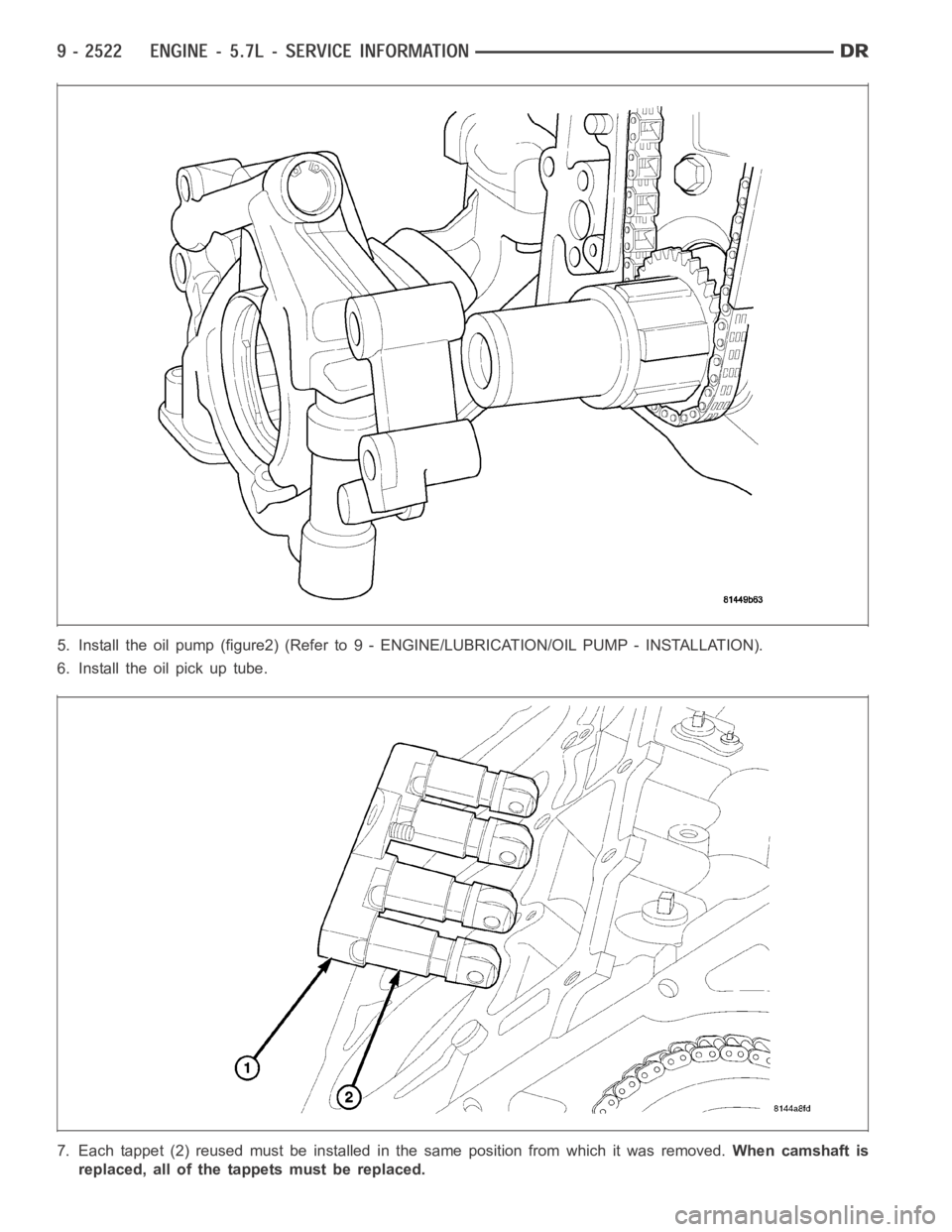
5. Install the oil pump (figure2) (Refer to 9 - ENGINE/LUBRICATION/OIL PUMP - INSTALLATION).
6. Install the oil pick up tube.
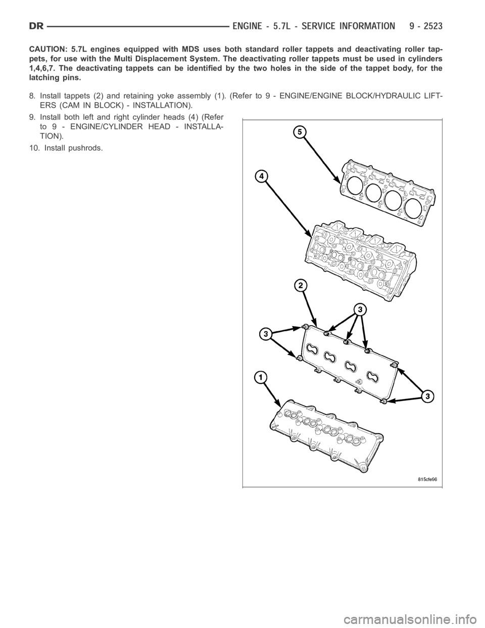
7. Each tappet (2) reused must be installed in the same position from which itwasremoved.When camshaft is
replaced, all of the tappets must be replaced.
Page 1832 of 5267
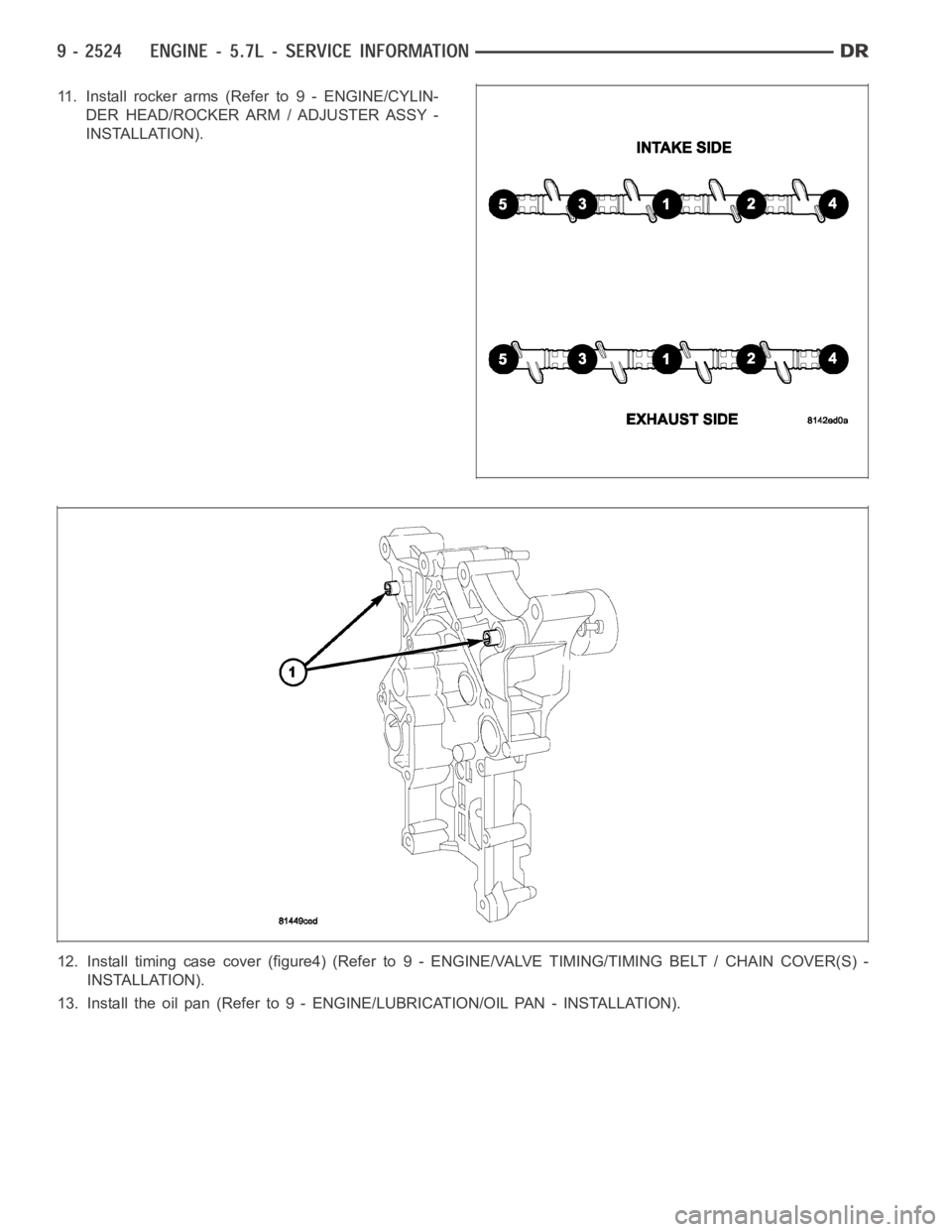
CAUTION: 5.7L engines equipped with MDS uses both standard roller tappetsand deactivating roller tap-
pets, for use with the Multi Displacement System. The deactivating rollertappets must be used in cylinders
1,4,6,7. The deactivating tappets can be identified by the two holes in theside of the tappet body, for the
latching pins.
8. Install tappets (2) and retaining yoke assembly (1). (Refer to 9 - ENGINE/ENGINE BLOCK/HYDRAULIC LIFT-
ERS (CAM IN BLOCK) - INSTALLATION).
9. Install both left and right cylinder heads (4) (Refer
to 9 - ENGINE/CYLINDER HEAD - INSTALLA-
TION).
10. Install pushrods.
Page 1833 of 5267
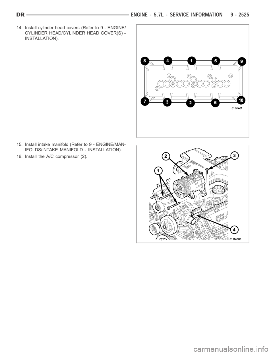
11. Installrockerarms(Referto9-ENGINE/CYLIN-
DER HEAD/ROCKER ARM / ADJUSTER ASSY -
INSTALLATION).
12. Install timing case cover (figure4) (Refer to 9 - ENGINE/VALVE TIMING/TIMING BELT / CHAIN COVER(S) -
INSTALLATION).
13. Install the oil pan (Refer to 9 - ENGINE/LUBRICATION/OIL PAN - INSTALLATION).
Page 1834 of 5267
14. Install cylinder head covers (Refer to 9 - ENGINE/
CYLINDER HEAD/CYLINDER HEAD COVER(S) -
INSTALLATION).
15. Install intake manifold (Refer to 9 - ENGINE/MAN-
IFOLDS/INTAKE MANIFOLD - INSTALLATION).
16. Install the A/C compressor (2).
Page 1835 of 5267
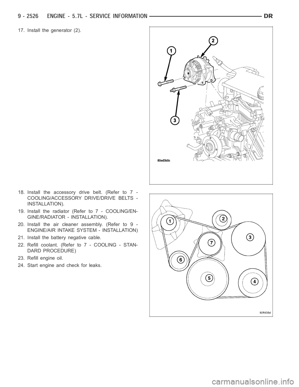
17. Install the generator (2).
18. Install the accessory drive belt. (Refer to 7 -
COOLING/ACCESSORY DRIVE/DRIVE BELTS -
INSTALLATION).
19. Install the radiator (Refer to 7 - COOLING/EN-
GINE/RADIATOR - INSTALLATION).
20. Install the air cleaner assembly. (Refer to 9 -
ENGINE/AIR INTAKE SYSTEM - INSTALLATION)
21. Install the battery negative cable.
22. Refill coolant. (Refer to 7 - COOLING - STAN-
DARD PROCEDURE)
23. Refill engine oil.
24. Start engine and check for leaks.
Page 1836 of 5267
CRANKSHAFT
REMOVAL
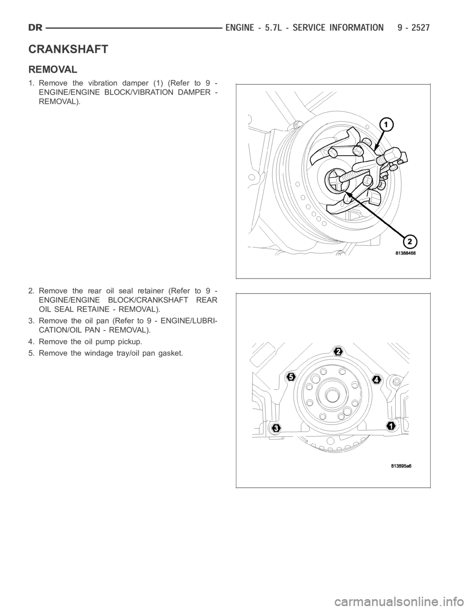
1. Remove the vibration damper (1) (Refer to 9 -
ENGINE/ENGINE BLOCK/VIBRATION DAMPER -
REMOVAL).
2. Remove the rear oil seal retainer (Refer to 9 -
ENGINE/ENGINE BLOCK/CRANKSHAFT REAR
OIL SEAL RETAINE - REMOVAL).
3. Remove the oil pan (Refer to 9 - ENGINE/LUBRI-
CATION/OIL PAN - REMOVAL).
4. Remove the oil pump pickup.
5. Remove the windage tray/oil pan gasket.
Page 1837 of 5267
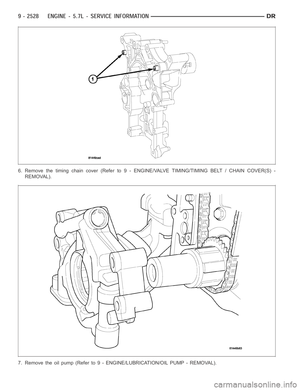
6. Remove the timing chain cover (Refer to 9 - ENGINE/VALVE TIMING/TIMING BELT / CHAIN COVER(S) -
REMOVAL).
7. Remove the oil pump (Refer to 9 - ENGINE/LUBRICATION/OIL PUMP - REMOVAL).
Page 1838 of 5267
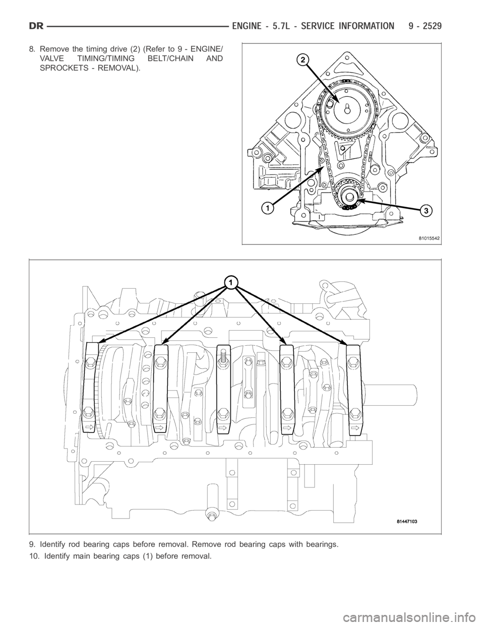
8. Removethetimingdrive(2)(Referto9-ENGINE/
VALVE TIMING/TIMING BELT/CHAIN AND
SPROCKETS - REMOVAL).
9. Identify rod bearing caps before removal. Remove rod bearing caps with bearings.
10. Identify main bearing caps (1) before removal.
Page 1839 of 5267
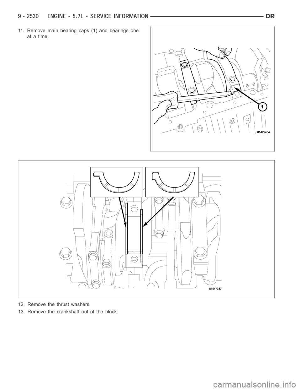
11. Remove main bearing caps (1) and bearings one
at a time.
12. Remove the thrust washers.
13. Remove the crankshaft out of the block.
Page 1840 of 5267
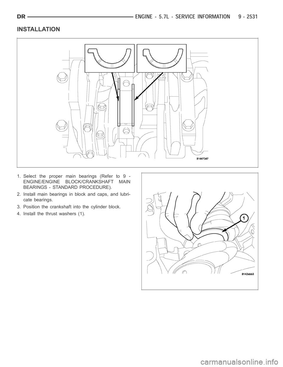
INSTALLATION
1. Select the proper main bearings (Refer to 9 -
ENGINE/ENGINE BLOCK/CRANKSHAFT MAIN
BEARINGS - STANDARD PROCEDURE).
2. Install main bearings in block and caps, and lubri-
cate bearings.
3. Position the crankshaft into the cylinder block.
4. Install the thrust washers (1).
Trending: service schedule, battery capacity, load capacity, hood release, brake, wipers, adding oil
