DODGE TRUCK 1993 Service Repair Manual
Manufacturer: DODGE, Model Year: 1993, Model line: TRUCK, Model: DODGE TRUCK 1993Pages: 1502, PDF Size: 80.97 MB
Page 1211 of 1502
21
- 210
TRANSMISSION
OVERHAUL-36RH/37RH
•
SPECIAL
TOOL
C-4171
BUSHING
m
REMOVAL
PUMP
HOUSING
SPECIAL
TOOL
C-4171
SPECIAL
TOOL
SP-3550
BUSHING
SPECIAL
TOOL
SP-5118
J9221-244
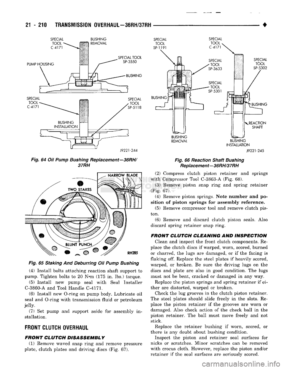
Fig.
64 Oil
Pump Bushing
Replacement—36RH/
37RH
mm
Fig.
65 Staking And Deburring Oil
Pump Bushing
(4) Install bolts attaching reaction shaft support to
pump. Tighten bolts to 20 N«m (175 in. lbs.) torque.
(5) Install new pump seal with Seal Installer
C-3860-A and Tool Handle C-4171.
(6) Install new O-ring on pump body. Lubricate oil
seal and O-ring with transmission fluid or petroleum
jelly.
(7) Set pump and support aside for assembly in
stallation.
FRONT
CLUTCH OVERHAUL
FRONT CLUTCH DISASSEMBLY (1) Remove waved snap ring and remove pressure
plate, clutch plates and driving discs (Fig. 67).
SPECIAL
TOOL
SP-119
SPECIAL
TOOL
C-4171
SPECIAL
TOOL
SP-5302
BUSHING BUSHING
X
REACTION
SHAFT
BUSHING
REMOVAL
BUSHING
INSTALLATION
J9221-245
Fig.
66 Reaction Shaft
Bushing
Replacement—36RH/37RH
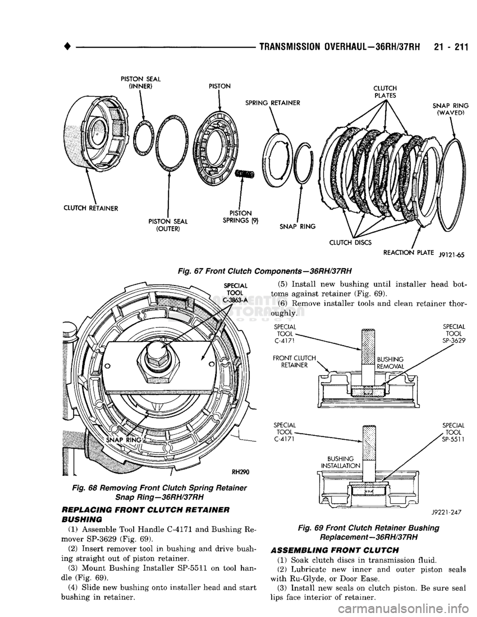
(2) Compress clutch piston retainer and springs
with Compressor Tool C-3863-A (Fig. 68).
(3) Remove piston snap ring and spring retainer
(Fig. 67).
(4) Remove piston springs. Note number and po
sition of piston springs for assembly reference.
(5) Remove compressor tool and remove clutch pis
ton.
(6) Remove and discard clutch piston seals. Also
discard spring retainer snap ring.
FRONT CLUTCH CLEANING AND INSPECTION Clean and inspect the front clutch components. Re
place the clutch discs if warped, worn, scored, burned or charred, the lugs are damaged, or if the facing is
flaking off. Replace the steel plates if heavily scored,
warped, or broken. Be sure the driving lugs on the discs and plate are also in good condition. The lugs
must not be bent, cracked or damaged in any way.
Replace the piston springs and spring retainer if ei
ther are distorted, warped or broken. Check the lug grooves in the clutch piston retainer.
The steel plates should slide freely in the slots. Re
place the piston retainer if the grooves are worn or damaged. Also check action of the check ball in the
piston retainer. The ball must move freely and not stick.
Replace the retainer bushing if worn, scored, or
there is any doubt about bushing condition.
Inspect the piston and retainer seal surfaces for
nicks or scratches. Minor scratches can be removed
with crocus cloth. However, replace the piston and/or
retainer if the seal surfaces are seriously scored.
Page 1212 of 1502
4 _
,
TRANSMISSION
OVERHAUL—3IRH/37RH
21 - 211
PISTON
SEAL
REACTION
PLATE
J9121-65
SPECIAL
TOOL
C-3863-A
Fig.
67 Front
Clutch
Components—36RH/37RH
(5) Install new bushing until installer head bot
toms against retainer (Fig. 69).
(6) Remove installer tools and clean retainer thor
oughly.
RH290
Fig.
68
Removing
Front
Clutch
Spring
Retainer
Snap
Ring-36RH/37RH
REPLACING
FRONT
CLUTCH
RETAINER
BUSHING
(1) Assemble Tool Handle C-4171 and Bushing Re
mover SP-3629 (Fig. 69). (2) Insert remover tool in bushing and drive bush
ing straight out of piston retainer. (3) Mount Bushing Installer SP-5511 on tool han
dle (Fig. 69).
(4) Slide new bushing onto installer head and start
bushing in retainer.
SPECIAL
TOOL-
C-4171
FRONT
CLUTCH
RETAINER
It
BUSHING
REMOVAL
SPECIAL
TOOL
SP-3629
SPECIAL
TOOL
C-4171
SPECIAL
TOOL
SP-5511
J9221-247
Fig.
69 Front
Clutch
Retainer
Bushing
Replacement—36RH/37RH
ASSEMBLING
FRONT
CLUTCH
(1) Soak clutch discs in transmission fluid.
(2) Lubricate new inner and outer piston seals
with Ru-Glyde, or Door Ease. (3) Install new seals on clutch piston. Be sure seal
lips face interior of retainer.
Page 1213 of 1502
21 - 212
TRANSMISSION OVERHAUL—36RH/37RH
• (4) Install clutch piston in retainer. Use twisting
motion to seat piston in retainer. Do not force pis
ton straight in. This could fold seals over caus
ing leakage and clutch slip.
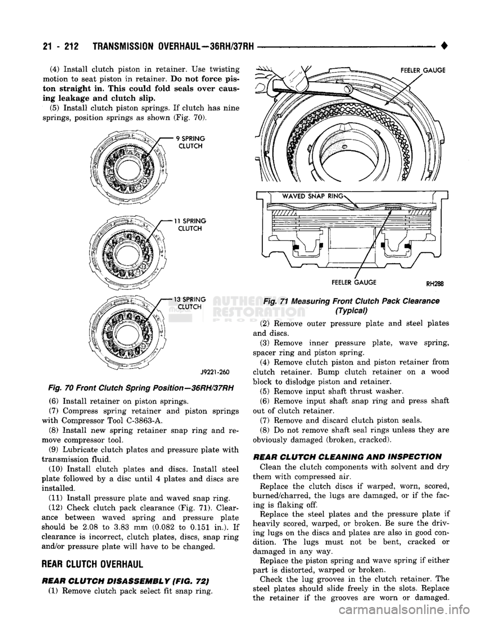
(5) Install clutch piston springs. If clutch has nine
springs, position springs as shown (Fig. 70). 9
SPRING
CLUTCH
11
SPRING CLUTCH
13
SPRING CLUTCH
J9221-260
Fig.
70 Front
Clutch
Spring
Position—36RH/37RH
(6) Install retainer on piston springs.
(7) Compress spring retainer and piston springs
with Compressor Tool C-3863-A.
(8) Install new spring retainer snap ring and re
move compressor tool.
(9) Lubricate clutch plates and pressure plate with
transmission fluid.
(10) Install clutch plates and discs. Install steel
plate followed by a disc until 4 plates and discs are installed.
(11) Install pressure plate and waved snap ring.
(12) Check clutch pack clearance (Fig. 71). Clear
ance between waved spring and pressure plate
should be 2.08 to 3.83 mm (0.082 to 0.151 in.). If
clearance is incorrect, clutch plates, discs, snap ring
and/or pressure plate will have to be changed.
REAR
CLUTCH OVERHAUL FEELER GAUGE
RH288
Fig.
71
Measuring
Front
Clutch
Pack
Clearance
(Typical)
(2) Remove outer pressure plate and steel plates
and discs. (3) Remove inner pressure plate, wave spring,
spacer ring and piston spring. (4) Remove clutch piston and piston retainer from
clutch retainer. Bump clutch retainer on a wood
block to dislodge piston and retainer.
(5) Remove input shaft thrust washer.
(6) Remove input shaft snap ring and press shaft
out of clutch retainer.
(7) Remove and discard clutch piston seals.
(8) Do not remove shaft seal rings unless they are
obviously damaged (broken, cracked).
REAR
CLUTCH CLEANING
AND
INSPECTION
Clean the clutch components with solvent and dry
them with compressed air.
Replace the clutch discs if warped, worn, scored,
burned/charred, the lugs are damaged, or if the fac ing is flaking off. Replace the steel plates and the pressure plate if
heavily scored, warped, or broken. Be sure the driv
ing lugs on the discs and plates are also in good con dition. The lugs must not be bent, cracked or
damaged in any way. Replace the piston spring and wave spring if either
part is distorted, warped or broken. Check the lug grooves in the clutch retainer. The
steel plates should slide freely in the slots. Replace
the retainer if the grooves are worn or damaged.
REAR
CLUTCH DISASSEMBLY
(FIG. 72)
(1) Remove clutch pack select fit snap ring.
Page 1214 of 1502
# — .—.—, , TRANSMISSION
OVERHAUL-3IRH/37RH
21 - 213
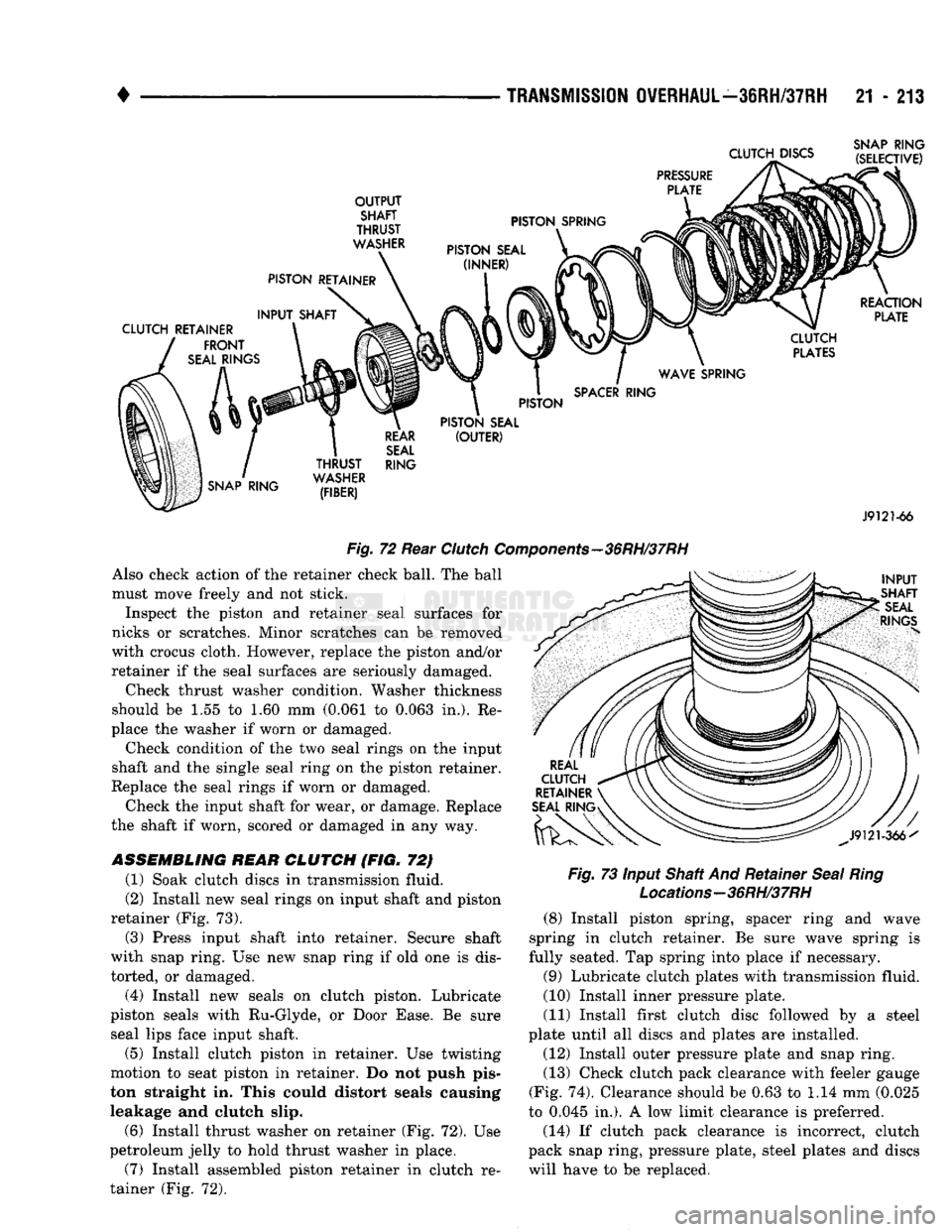
Fig.
72
Rear
Clutch
C
Also check action
of the
retainer check ball.
The
ball
must move freely
and not
stick.
Inspect
the
piston
and
retainer seal surfaces
for
nicks
or
scratches. Minor scratches
can be
removed
with crocus cloth. However, replace
the
piston and/or
retainer
if the
seal surfaces
are
seriously damaged.
Check thrust washer condition. Washer thickness
should
be 1.55 to 1.60 mm
(0.061
to
0.063
in.). Re
place
the
washer
if
worn
or
damaged.
Check condition
of the two
seal rings
on the
input
shaft
and the
single seal ring
on the
piston retainer.
Replace
the
seal rings
if
worn
or
damaged.
Check
the
input shaft
for
wear,
or
damage. Replace
the shaft
if
worn, scored
or
damaged
in any way.
ASSEMBLING
REAR
CLUTCH
(FIG. 72)
(1) Soak clutch discs
in
transmission fluid.
(2) Install
new
seal rings
on
input shaft
and
piston
retainer
(Fig. 73).
(3) Press input shaft into retainer. Secure shaft
with snap ring.
Use new
snap ring
if old one is
dis
torted,
or
damaged.
(4) Install
new
seals
on
clutch piston. Lubricate
piston seals with Ru-Glyde,
or
Door Ease.
Be
sure seal lips face input shaft.
(5) Install clutch piston
in
retainer.
Use
twisting
motion
to
seat piston
in
retainer.
Do not
push pis
ton straight
in.
This could distort seals causing
leakage
and
clutch slip.
(6) Install thrust washer
on
retainer
(Fig. 72). Use
petroleum jelly
to
hold thrust washer
in
place.
(7) Install assembled piston retainer
in
clutch
re
tainer
(Fig. 72).
-36RH/37RH
Fig.
73
Input Shaft
And
Retainer
Seal
Ring
Locations-36RH/37RH (8) Install piston spring, spacer ring
and
wave
spring
in
clutch retainer.
Be
sure wave spring
is
fully seated.
Tap
spring into place
if
necessary.
(9) Lubricate clutch plates with transmission fluid.
(10) Install inner pressure plate.
(11) Install first clutch disc followed
by a
steel
plate until
all
discs
and
plates
are
installed.
(12) Install outer pressure plate
and
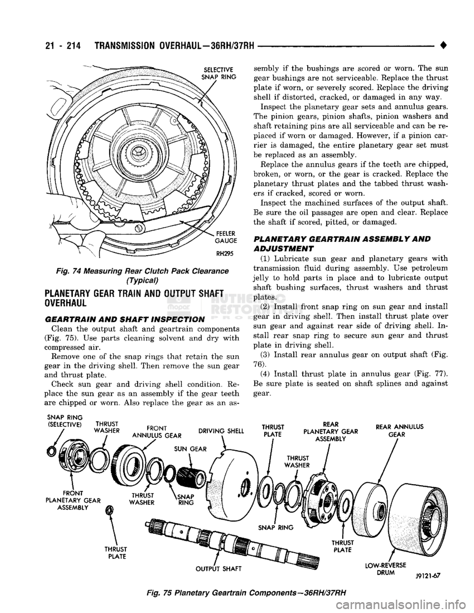
snap ring. (13) Check clutch pack clearance with feeler gauge
(Fig.
74).
Clearance should
be 0.63 to 1.14 mm
(0.025
to 0.045
in.). A low
limit clearance
is
preferred.
(14)
If
clutch pack clearance
is
incorrect, clutch
pack snap ring, pressure plate, steel plates
and
discs
will have
to be
replaced.
Page 1215 of 1502
21
- 214
TRANSMISSION
OVERHAUL—3SRH/37RH
SELECTIVE
SNAP
RING
FEELER
GAUGE
RH295
Fig.
74
Measuring
Rear
Clutch
Pack
Clearance
(Typical)
PLANETARY
GEAR TRAIN AND OUTPUT SHAFT
OVERHAUL
GEARTRAIN AND
SHAFT INSPECTION
Clean the output shaft and geartrain components
(Fig. 75). Use parts cleaning solvent and dry with
compressed air.
Remove one of the snap rings that retain the sun
gear in the driving shell. Then remove the sun gear and thrust plate.
Check sun gear and driving shell condition. Re
place the sun gear as an assembly if the gear teeth are chipped or worn. Also replace the gear as an as-
SNAP
RING
(SELECTIVE)
THRUST
WASHER
FRONT
ANNULUS GEAR
sembly if the bushings are scored or worn. The sun
gear bushings are not serviceable. Replace the thrust
plate if worn, or severely scored. Replace the driving shell if distorted, cracked, or damaged in any way.
Inspect the planetary gear sets and annulus gears.
The pinion gears, pinion shafts, pinion washers and shaft retaining pins are all serviceable and can be re
placed if worn or damaged. However, if a pinion car rier is damaged, the entire planetary gear set must
be replaced as an assembly.
Replace the annulus gears if the teeth are chipped,
broken, or worn, or the gear is cracked. Replace the
planetary thrust plates and the tabbed thrust wash ers if cracked, scored or worn.
Inspect the machined surfaces of the output shaft.
Be sure the oil passages are open and clear. Replace
the shaft if scored, pitted, or damaged.
PLANETARY GEARTRAIN ASSEMBLY AND
ADJUSTMENT
(1) Lubricate sun gear and planetary gears with
transmission fluid during assembly. Use petroleum
jelly to hold parts in place and to lubricate output shaft bushing surfaces, thrust washers and thrust
plates.
(2) Install front snap ring on sun gear and install
gear in driving shell. Then install thrust plate over
sun gear and against rear side of driving shell. In stall rear snap ring to secure sun gear and thrust
plate in driving shell.
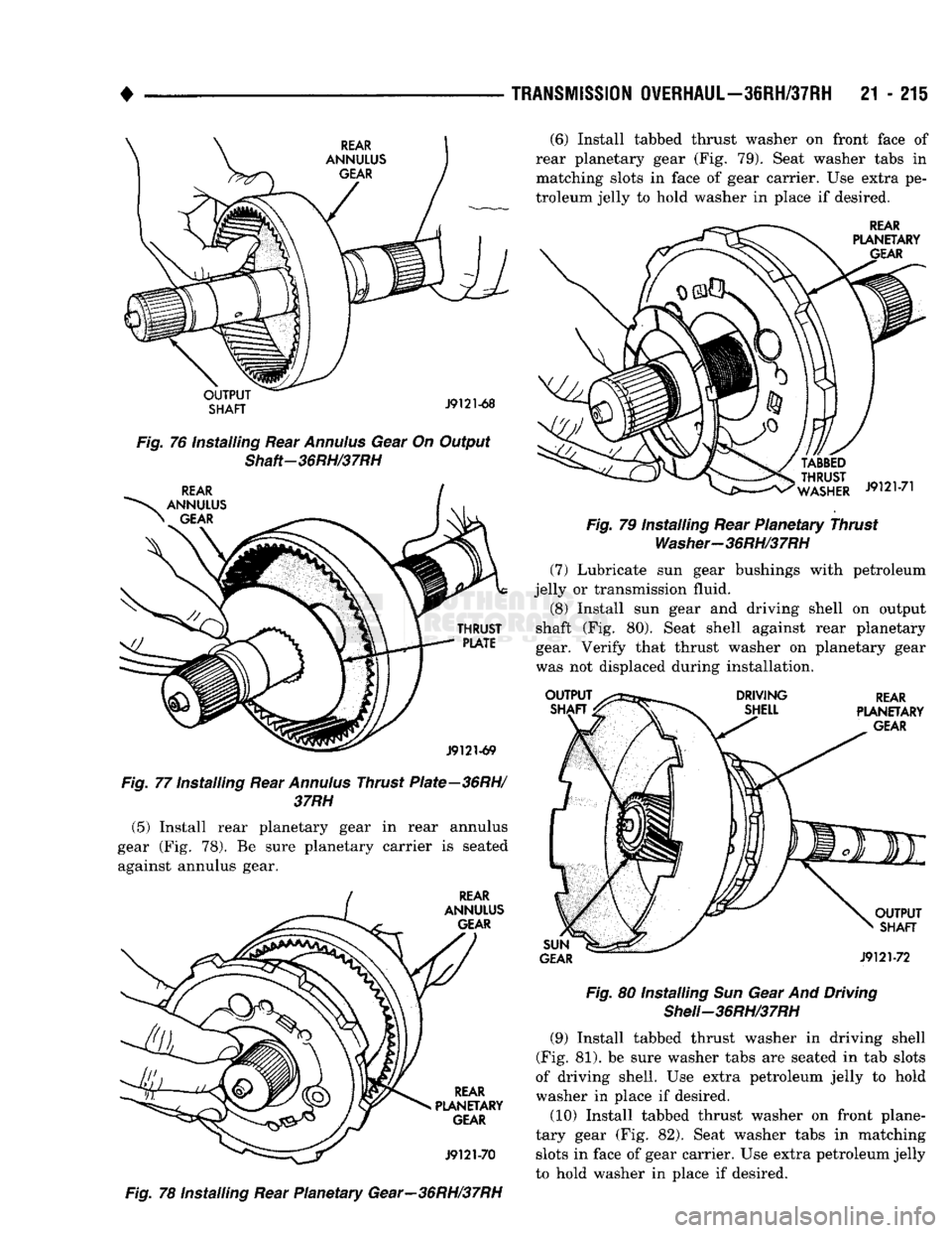
(3) Install rear annulus gear on output shaft (Fig.
76).
(4) Install thrust plate in annulus gear (Fig. 77).
Be sure plate is seated on shaft splines and against gear.
DRIVING SHELL
THRUST
PLATE
REAR
PLANETARY GEAR
ASSEMBLY
REAR
ANNULUS
GEAR
FRONT
PLANETARY GEAR
ASSEMBLY
THRUST
PLATE
OUTPUT
SHAFT
LOW-REVERSE
DRUM
J9121-67
Fig.
75 Planetary
Geartrain
Components—36RH/37RH
Page 1216 of 1502
•
TRANSMISSION
OVERHAUL—36RH/37RH
21 - 215
OUTPUT
SHAFT
J9121-68
Fig.
76 Installing Rear
Annulus
Gear On Output
Shaft-36RH/37RH
THRUST
PLATE
J9121-69
Fig.
77 Installing Rear
Annulus
Thrust Plate—36RH/ 37RH
(5) Install rear planetary gear in rear annulus
gear (Fig. 78). Be sure planetary carrier is seated against annulus gear.
REAR
ANNULUS GEAR REAR
PLANETARY GEAR
J9121-70
Fig.
78 installing Rear Planetary Gear—36RH/37RH (6) Install tabbed thrust washer on front face of
rear planetary gear (Fig. 79). Seat washer tabs in matching slots in face of gear carrier. Use extra pe
troleum jelly to hold washer in place if desired.
REAR
PLANETARY GEAR
WASHER
J9121-71
Fig.
79 Installing Rear Planetary Thrust
Washer-36RH/37RH
(7) Lubricate sun gear bushings with petroleum
jelly or transmission fluid.
(8) Install sun gear and driving shell on output
shaft (Fig. 80). Seat shell against rear planetary
gear. Verify that thrust washer on planetary gear
was not displaced during installation.
OUTPUT
SHAFT DRIVING
SHELL REAR
PLANETARY
GEAR
SUN
GEAR
OUTPUT
SHAFT
J9121-72
Fig.
80 Installing Sun Gear And Driving
Shell-36RH/37RH
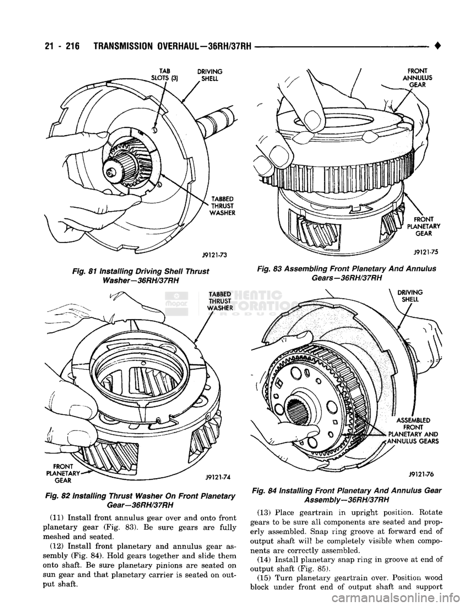
(9) Install tabbed thrust washer in driving shell
(Fig. 81). be sure washer tabs are seated in tab slots
of driving shell. Use extra petroleum jelly to hold
washer in place if desired.
(10) Install tabbed thrust washer on front plane
tary gear (Fig. 82). Seat washer tabs in matching slots in face of gear carrier. Use extra petroleum jelly
to hold washer in place if desired.
Page 1217 of 1502
21-216
TRANSMISSION
OVERHAUL—36RH/37RH
Fig.
81 Installing Driving
Shell
Thrust
Washer-36RH/37RH
Fig.
82 Installing Thrust
Washer
On Front Planetary
Gear—36RH/37RH
(11) Install front annulus gear over and onto front
planetary gear (Fig. 83). Be sure gears are fully meshed and seated.
(12) Install front planetary and annulus gear as
sembly (Fig. 84). Hold gears together and slide them
onto shaft. Be sure planetary pinions are seated on sun gear and that planetary carrier is seated on out
put shaft. •
Fig.
83
Assembling
Front Planetary And
Annulus
Gears—36RH/37RH
Fig.
84 Installing Front Planetary And
Annulus
Gear
Assembly-36RH/37RH
(13) Place geartrain in upright position. Rotate
gears to be sure all components are seated and prop
erly assembled. Snap ring groove at forward end of
output shaft will be completely visible when compo
nents are correctly assembled.
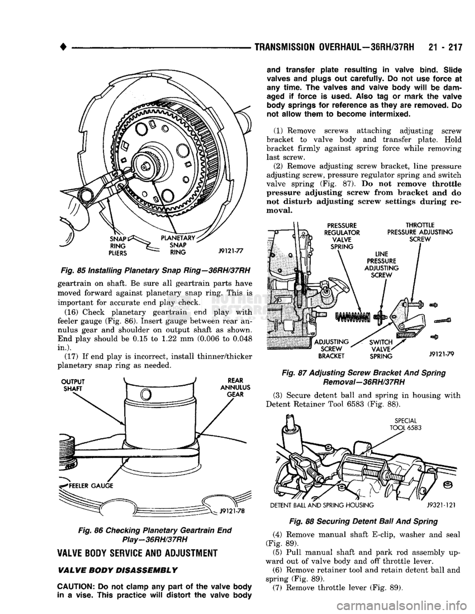
(14) Install planetary snap ring in groove at end of
output shaft (Fig. 85). (15) Turn planetary geartrain over. Position wood
block under front end of output shaft and support
TAB
DRIVING
Page 1218 of 1502
•
TRANSMISSION
OVERHAUL—36RH/37RH
21 - 217
Fig.
85 Installing Planetary
Snap
Ring—36RH/37RH
geartrain on shaft. Be sure all geartrain parts have
moved forward against planetary snap ring. This is
important for accurate end play check.
(16) Check planetary geartrain end play with
feeler gauge (Fig. 86). Insert gauge between rear an
nulus gear and shoulder on output shaft as shown.
End play should be 0.15 to 1.22 mm (0.006 to 0.048
in.).
(17) If end play is incorrect, install thinner/thicker
planetary snap ring as needed.
Fig.
86
Checking
Planetary
Geartrain
End
Play-36RH/37RH
VALVE
BODY
SERVICE
AND
ADJUSTMENT
VALWE
BODY DISASSEMBLY
CAUTION:
Do not
clamp
any
part
of the
valve
body
in
a
vise.
This
practice
will
distort
the
valve
body
and
transfer
plate
resulting
in
valve
bind.
Slide
valves
and
plugs
out
carefully.
Do not use
force
at
any
time.
The
valves
and
valve
body
will
be
dam
aged
if
force
is
used.
Also
tag or
mark
the
valve
body
springs
for
reference
as
they
are
removed.
Do
not
allow
them
to
become
intermixed.
(1) Remove screws attaching adjusting screw
bracket to valve body and transfer plate. Hold
bracket firmly against spring force while removing last screw. (2) Remove adjusting screw bracket, line pressure
adjusting screw, pressure regulator spring and switch
valve spring (Fig. 87). Do not remove throttle
pressure adjusting screw from bracket and do
not disturb adjusting screw settings during re
moval.
Fig.
87 Adjusting
Screw
Bracket And
Spring
Removal-36RH/37RH (3) Secure detent ball and spring in housing with
Detent Retainer Tool 6583 (Fig. 88).
DETENT
BALL
AND
SPRING
HOUSING
J932M21
Fig.
88
Securing
Detent
Ball
And
Spring
(4) Remove manual shaft E-clip, washer and seal
(Fig. 89). (5) Pull manual shaft and park rod assembly up
ward out of valve body and off throttle lever. (6) Remove retainer tool and retain detent ball and
spring (Fig. 89).
(7) Remove throttle lever (Fig. 89),
Page 1219 of 1502
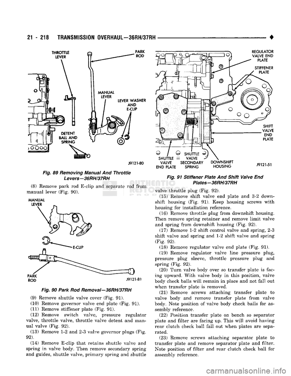
21 - 218
TRANSMISSION OVERHAUL—36RH/37RH
•
THROTTLE
LEVER
PARK
ROD
LEVER
WASHER
AND
E-CLIP
J9121-80
Fig.
89 Removing Manual And Throttle
Levers-36RH/37RH (8) Remove park rod E-clip and separate rod from
manual lever (Fig. 90).
MANUAL LEVER
PARK
ROD
J9121-81
Fig.
90
Park
Rod Removal-36RH/37RH
(9) Remove shuttle valve cover (Fig. 91). (10) Remove governor valve end plate (Fig. 91).
(11) Remove stiffener plate (Fig. 91).
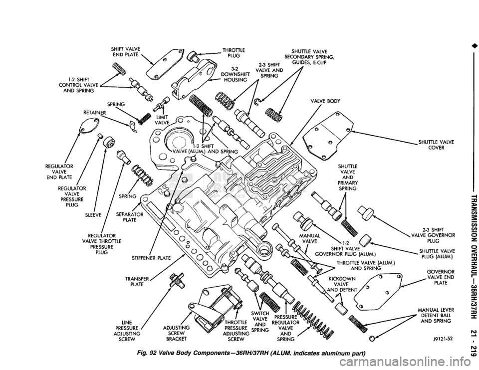
(12) Remove switch valve, pressure regulator
valve, throttle valve, throttle valve detent and man
ual valve (Fig. 92).
(13) Remove 1-2 and 2-3 valve governor plugs (Fig.
92).
(14) Remove E-clip that retains shuttle valve and
spring in valve body. Then remove secondary spring
and guides, shuttle valve, primary spring and shuttle
REGULATOR
VALVE
END
PLATE
STIFFENER PLATE
Q /
SHUTTLE SHUTTLE
=
VALVE VALVE SECONDARY
END PLATE SPRING DOWNSHIFT
HOUSING SHIFT
VALVE END
PLATE
J9121-51
Fig.
91 Stiffener
Plate
And Shift
Valve
End Piates-36RH/37RH
valve throttle plug (Fig. 92). (15) Remove shift valve end plate and 3-2 down
shift housing (Fig. 91). Keep housing screws with
housing for installation reference. (16) Remove throttle plug from downshift housing.
Then remove spring retainer and remove limit valve and spring from downshift housing (Fig. 92).
(17) Remove 1-2 shift control valve and spring, 2-3
shift valve and spring and 1-2 shift valve and spring (Fig. 92). (18) Remove regulator valve end plate (Fig. 91).
(19) Remove regulator valve line pressure plug,
pressure plug sleeve, throttle pressure plug and spring (Fig. 92).
(20) Turn valve body over so transfer plate is fac
ing upward. With valve body in this position, valve
body check balls will remain in place and not fall out
when transfer plate is removed.
(21) Remove screws attaching transfer plate to
valve body and remove transfer plate from valve
body. Note position of valve body check balls for as sembly reference. (22) Position transfer plate on bench so separator
plate and filter are facing up. This will avoid having
rear clutch check ball fall out when plates are sepa rated.
(23) Remove screws attaching separator plate to
transfer plate and remove separator plate and filter. Note position of filter and rear clutch check ball for
assembly reference.
Page 1220 of 1502
SHIFT VALVE
END PLATE THROTTLE
PLUG
1-2 SHIFT
CONTROL VALVE AND SPRING SHUTTLE VALVE
SECONDARY SPRING,
2-3 SHIFT
GU,DES- E"CL,P
VALVE
AND
SPRING
REGULATOR VALVE
END PLATE SHUTTLE VALVE
COVER
REGULATOR VALVE
PRESSURE PLUG
REGULATOR
VALVE THROTTLE PRESSURE PLUG 2-3 SHIFT
VALVE GOVERNOR PLUG
SHUTTLE VALVE PLUG (ALUM.)
LINE
PRESSURE
ADJUSTING SCREW GOVERNOR
VALVE
END
PLATE
MANUAL LEVER DETENT BALL
AND SPRING
ADJUSTING SCREW
BRACKET J9121-52
Fig. 92 Valve
Body
Components—36RH/37RH (ALUM, indicates aluminum part)