engine FIAT FULLBACK 2017 Owner handbook (in English)
[x] Cancel search | Manufacturer: FIAT, Model Year: 2017, Model line: FULLBACK, Model: FIAT FULLBACK 2017Pages: 312, PDF Size: 12.31 MB
Page 228 of 312
174)Never tow an automatic transmission
vehicle with the front wheels up (and the
rear wheels on the ground) (Type B) when
the automatic transmission fluid level is low.
This may cause serious and expensive
damage to the transmission.
175)When the engine is not running, the
brake booster and power steering pump do
not operate. This means higher brake
depression force and higher steering effort
are required. Therefore, vehicle operation is
very difficult.
176)Do not leave the ignition switch in the
“LOCK” position or the operation mode in
OFF. The steering wheel will lock, causing
loss of control.
177)On vehicles with super select 4WD II,
when you are going to tow another vehicle,
set the drive mode-selector to “4H”
position. Selecting “2H” drive may increase
the differential oil temperature, resulting in
possible damage to the driving system.
Further, the drive train will be subjected to
excessive loading possibly leading to oil
leakage, component seizure, or other
serious faults.OPERATION UNDER
ADVERSE DRIVING
CONDITIONS
On a flooded road
Avoid flooded roads. In the event
driving flooded roads, doing so may
cause the following serious damage to
the vehicle.
Engine stalling
Short in electrical components
Engine damage caused by water
immersion
After driving flooded roads, be sure to
have an inspection at a Fiat Dealership
and take the necessary measures or
repair.
When driving in rain, or water-covered
roads, or through a car wash, water
could enter the brake discs, resulting in
temporarily ineffective brakes. In such
cases, lightly depress the brake pedal
to see if the brakes operate properly. If
they do not, lightly depress the pedal
several times while driving in order to
dry the brake pads.
On a wet road
When driving in rain or on a road with
many puddles a layer of water may
form between the tyres and the road
surface. This reduces a tyre’s frictional
resistance on the road, resulting in loss
of steering stability and braking
capability.To cope with this, observe the following
items:
(a) Drive your vehicle at a slow speed.
(b) Do not drive on worn tyres.
(c) Always maintain the specified tyre
inflation pressures.
On a snow-covered or frozen road
When driving on a snow-covered or
frozen road, it is recommended that you
use snow tyres or snow traction device
(tyre chains). Refer to the “Snow tyres”
and “Snow traction device (tyre chains)”
sections.
Avoid high-speed operation, sudden
acceleration, abrupt brake application
and sharp cornering.
Depressing the brake pedal during
travel on snowy or icy roads may cause
tyre slippage and skidding. When
traction between the tyres and the road
is reduced the wheels may skid and the
vehicle cannot readily be brought to a
stop by conventional braking
techniques. Braking will differ,
depending upon whether you have
anti-lock brake system (ABS). If you do
have ABS, brake by pressing the brake
pedal hard, and keeping it pressed. If
you do not have ABS, pump the brake
pedal with short rapid jabs, each time
fully applying and fully releasing for
greatest effect.
Allow extra distance between your
vehicle and the vehicle in front of you,
and avoid sudden braking.
226
IN AN EMERGENCY
Page 229 of 312
Accumulation of ice on the braking
system can cause the wheels to lock.
Pull away from a standstill slowly after
confirming safety around the vehicle.
330)
On a bumpy or rutted road
Drive as slow as possible when driving
on bumpy or rutted roads.
178)
WARNING
330)Do not press the accelerator pedal
rapidly. If the wheels break free of the ice,
the vehicle could suddenly start moving
and possibly cause an accident.
IMPORTANT
178)The impact on tyres and/or wheels
when driving on a bumpy or rutted road
can damage the tyre and/or wheel.
FUSIBLE LINKS
The fusible links will melt to prevent a
fire if a large current attempts to flow
through certain electrical systems. In
case of a melted fuse link, we
recommend you to have your vehicle
inspected. For the fusible links, please
refer to “Passenger compartment fuse
location table” and “Engine
compartment fuse location table”.
331)
WARNING
331)Fusible links must not be replaced by
any other device. Failing to fit the correct
fusible may result in fire in the vehicle,
property destruction and serious or fatal
injuries at any time.
FUSES
Fuse block location
To prevent damage to the electrical
system due to short-circuiting or
overloading, each individual circuit is
provided with a fuse. There are fuse
blocks in the passenger compartment
and in the engine compartment.
Passenger compartment (LHD
vehicles)
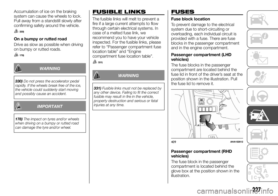
The fuse blocks in the passenger
compartment are located behind the
fuse lid in front of the driver’s seat at the
position shown in the illustration. Pull
the fuse lid to remove it.
Passenger compartment (RHD
vehicles)
The fuse block in the passenger
compartment is located behind the
glove box at the position shown in the
illustration.
409AHA102612
227
Page 230 of 312
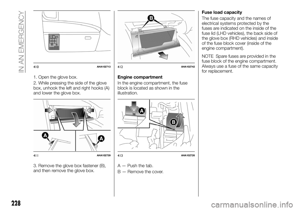
1. Open the glove box.
2. While pressing the side of the glove
box, unhook the left and right hooks (A)
and lower the glove box.
3. Remove the glove box fastener (B),
and then remove the glove box.Engine compartment
In the engine compartment, the fuse
block is located as shown in the
illustration.
A — Push the tab.
B — Remove the cover.Fuse load capacity
The fuse capacity and the names of
electrical systems protected by the
fuses are indicated on the inside of the
fuse lid (LHD vehicles), the back side of
the glove box (RHD vehicles) and inside
of the fuse block cover (inside of the
engine compartment).
NOTE Spare fuses are provided in the
fuse block of the engine compartment.
Always use a fuse of the same capacity
for replacement.
410AHA102713
411AHA102739
412AHA102742
413AHA102726
228
IN AN EMERGENCY
Page 232 of 312
No. Electrical system Capacity
7 Tail lamp (right) 7.5 A
8 Outside rear view mirrors 7.5 A
9 Engine control unit 7.5 A
10 Control unit 7.5 A
11 Rear fog lamp 10 A
12 Central door lock 15 A
13 Room lamp 15 A
14 Rear window wiper 15 A
15 Gauge 10 A
16 Relay 7.5 A
17 Heated seat 20 A
18 Option 10 A
19 Heated door mirror 7.5 A
20 Windscreen wiper 20 A
21 Reversing lamps 7.5 A
22 Demister 30 A
23 Heater 30 A
24 Power seat 40 A*
25 Radio 10 A
26 Electronic controlled unit 20 A
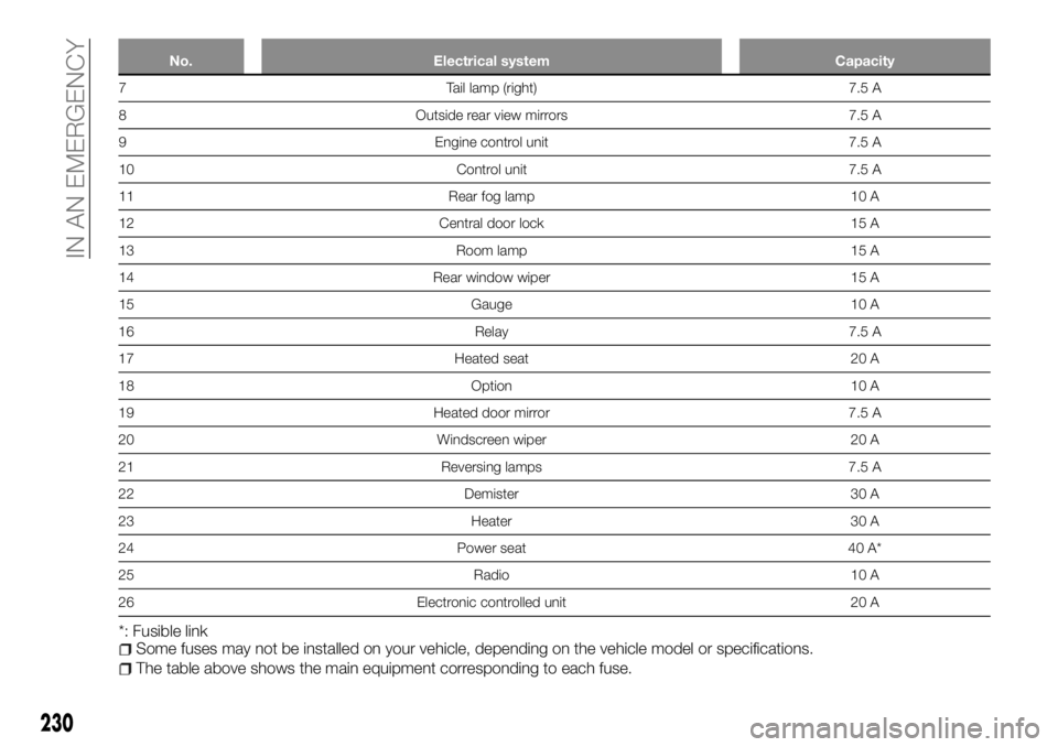
*: Fusible linkSome fuses may not be installed on your vehicle, depending on the vehicle model or specifications.
The table above shows the main equipment corresponding to each fuse.
230
IN AN EMERGENCY
Page 233 of 312
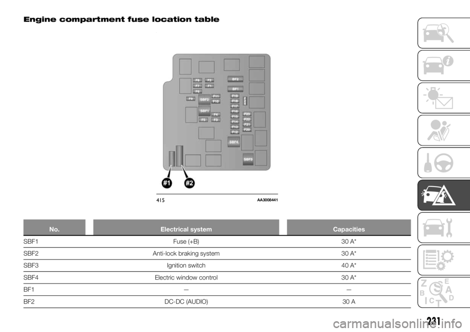
Engine compartment fuse location table
No. Electrical system Capacities
SBF1 Fuse (+B) 30 A*
SBF2 Anti-lock braking system 30 A*
SBF3 Ignition switch 40 A*
SBF4 Electric window control 30 A*
BF1 — —
BF2 DC-DC (AUDIO) 30 A
415AA3008441
231
Page 234 of 312
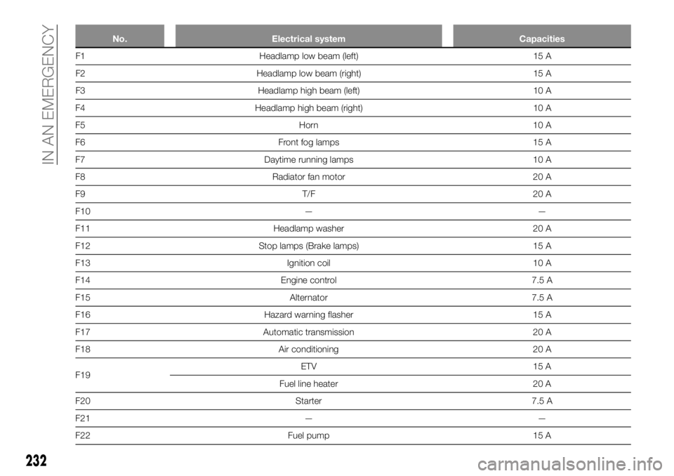
No. Electrical system Capacities
F1 Headlamp low beam (left) 15 A
F2 Headlamp low beam (right) 15 A
F3 Headlamp high beam (left) 10 A
F4 Headlamp high beam (right) 10 A
F5 Horn 10 A
F6 Front fog lamps 15 A
F7 Daytime running lamps 10 A
F8 Radiator fan motor 20 A
F9 T/F 20 A
F10 — —
F11 Headlamp washer 20 A
F12 Stop lamps (Brake lamps) 15 A
F13 Ignition coil 10 A
F14 Engine control 7.5 A
F15 Alternator 7.5 A
F16 Hazard warning flasher 15 A
F17 Automatic transmission 20 A
F18 Air conditioning 20 A
F19ETV 15 A
Fuel line heater 20 A
F20 Starter 7.5 A
F21 — —
F22 Fuel pump 15 A
232
IN AN EMERGENCY
Page 235 of 312
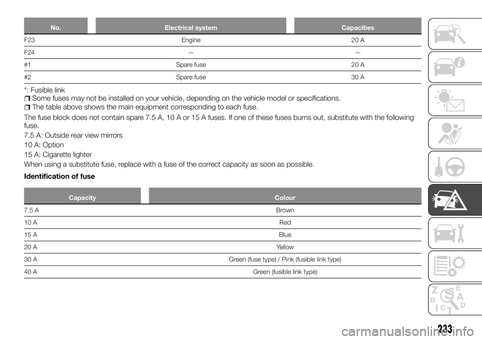
No. Electrical system Capacities
F23 Engine 20 A
F24 — —
#1 Spare fuse 20 A
#2 Spare fuse 30 A
*: Fusible linkSome fuses may not be installed on your vehicle, depending on the vehicle model or specifications.
The table above shows the main equipment corresponding to each fuse.
The fuse block does not contain spare 7.5 A, 10 A or 15 A fuses. If one of these fuses burns out, substitute with the following
fuse.
7.5 A: Outside rear view mirrors
10 A: Option
15 A: Cigarette lighter
When using a substitute fuse, replace with a fuse of the correct capacity as soon as possible.
Identification of fuse
Capacity Colour
7.5 ABrown
10 ARed
15 ABlue
20 AYellow
30 A Green (fuse type) / Pink (fusible link type)
40 AGreen (fusible link type)
233
Page 236 of 312
Fuse replacement
332) 333) 334) 335) 336) 337)
179)
1. Before replacing a fuse, always turn
off the electrical circuit concerned and
place the ignition switch in the “LOCK”
position or put the operation mode in
OFF.
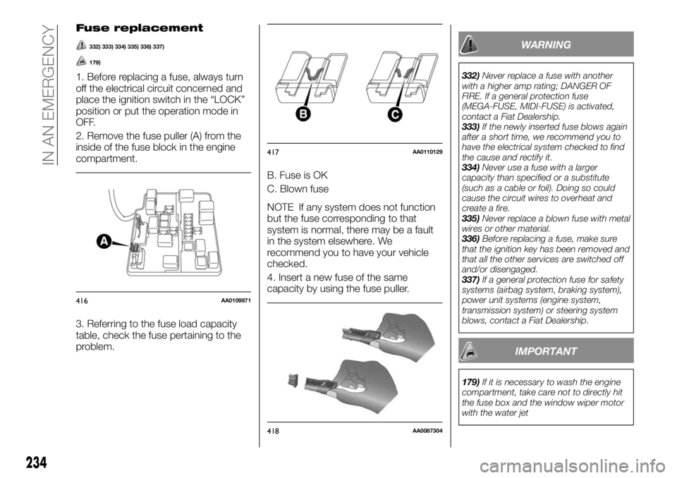
2. Remove the fuse puller (A) from the
inside of the fuse block in the engine
compartment.
3. Referring to the fuse load capacity
table, check the fuse pertaining to the
problem.B. Fuse is OK
C. Blown fuse
NOTE If any system does not function
but the fuse corresponding to that
system is normal, there may be a fault
in the system elsewhere. We
recommend you to have your vehicle
checked.
4. Insert a new fuse of the same
capacity by using the fuse puller.
WARNING
332)Never replace a fuse with another
with a higher amp rating; DANGER OF
FIRE. If a general protection fuse
(MEGA-FUSE, MIDI-FUSE) is activated,
contact a Fiat Dealership.
333)If the newly inserted fuse blows again
after a short time, we recommend you to
have the electrical system checked to find
the cause and rectify it.
334)Never use a fuse with a larger
capacity than specified or a substitute
(such as a cable or foil). Doing so could
cause the circuit wires to overheat and
create a fire.
335)Never replace a blown fuse with metal
wires or other material.
336)Before replacing a fuse, make sure
that the ignition key has been removed and
that all the other services are switched off
and/or disengaged.
337)If a general protection fuse for safety
systems (airbag system, braking system),
power unit systems (engine system,
transmission system) or steering system
blows, contact a Fiat Dealership.
IMPORTANT
179)If it is necessary to wash the engine
compartment, take care not to directly hit
the fuse box and the window wiper motor
with the water jet
416AA0109871
417AA0110129
418AA0087304
234
IN AN EMERGENCY
Page 244 of 312
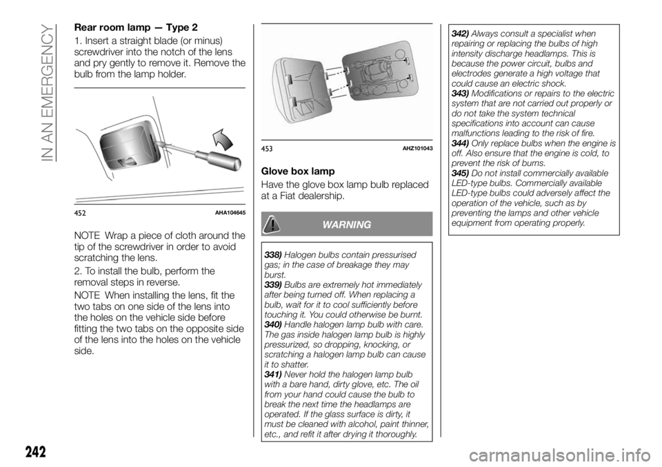
Rear room lamp — Type 2
1. Insert a straight blade (or minus)
screwdriver into the notch of the lens
and pry gently to remove it. Remove the
bulb from the lamp holder.
NOTE Wrap a piece of cloth around the
tip of the screwdriver in order to avoid
scratching the lens.
2. To install the bulb, perform the
removal steps in reverse.
NOTE When installing the lens, fit the
two tabs on one side of the lens into
the holes on the vehicle side before
fitting the two tabs on the opposite side
of the lens into the holes on the vehicle
side.Glove box lamp
Have the glove box lamp bulb replaced
at a Fiat dealership.
WARNING
338)Halogen bulbs contain pressurised
gas; in the case of breakage they may
burst.
339)Bulbs are extremely hot immediately
after being turned off. When replacing a
bulb, wait for it to cool sufficiently before
touching it. You could otherwise be burnt.
340)Handle halogen lamp bulb with care.
The gas inside halogen lamp bulb is highly
pressurized, so dropping, knocking, or
scratching a halogen lamp bulb can cause
it to shatter.
341)Never hold the halogen lamp bulb
with a bare hand, dirty glove, etc. The oil
from your hand could cause the bulb to
break the next time the headlamps are
operated. If the glass surface is dirty, it
must be cleaned with alcohol, paint thinner,
etc., and refit it after drying it thoroughly.342)Always consult a specialist when
repairing or replacing the bulbs of high
intensity discharge headlamps. This is
because the power circuit, bulbs and
electrodes generate a high voltage that
could cause an electric shock.
343)Modifications or repairs to the electric
system that are not carried out properly or
do not take the system technical
specifications into account can cause
malfunctions leading to the risk of fire.
344)Only replace bulbs when the engine is
off. Also ensure that the engine is cold, to
prevent the risk of burns.
345)Do not install commercially available
LED-type bulbs. Commercially available
LED-type bulbs could adversely affect the
operation of the vehicle, such as by
preventing the lamps and other vehicle
equipment from operating properly.
452AHA104645
453AHZ101043
242
IN AN EMERGENCY
Page 245 of 312
SERVICING AND MAINTENANCE
Correct maintenance permits the
performance of the car to be
maintained over time, as well as limited
running costs and safeguarding the
efficiency of the safety systems.
This chapter explains how.SERVICE PRECAUTIONS.......244
SCHEDULED SERVICING PLAN . .245
PERIODIC CHECKS..........250
DEMANDING VEHICLE USE.....250
CHECKING LEVELS..........251
CATALYTIC CONVERTER.......252
ENGINE OIL...............252
ENGINE COOLANT...........253
WASHER FLUID.............255
BRAKE FLUID..............255
CLUTCH FLUID.............256
POWER STEERING FLUID......257
BATTERY.................258
WIPER BLADE REPLACEMENT . . .260
GENERAL MAINTENANCE......261
VEHICLE CARE PRECAUTIONS. . .261
CLEANING THE INTERIOR OF
YOUR VEHICLE.............262
CLEANING THE EXTERIOR OF
YOUR VEHICLE.............263
TYRES...................267
243