FIAT TEMPRA 1988 Service And Manual PDF
Manufacturer: FIAT, Model Year: 1988, Model line: TEMPRA, Model: FIAT TEMPRA 1988Pages: 171, PDF Size: 18.05 MB
Page 61 of 171
PART A: ENGINE
PART A: Contents
Job 1. Petrol engine. Timing belt
-
replacement and Job 12. Petrol engine. Mountings
-
replacement.
adjustment. Job 13. Diesel engine. Timing belt
-
replacement and
Job 2. Petrol engine. Cylinder head
-
removal. adjustment. •
Job 3. Petrol engine. Cylinder head and camshaft housing -Job 14. Diesel engine. Cylinder head
-
removal.
refitting. Job 15. Diesel engine. Cylinder head
-
refitting.
Job
4.
Petrol engine. Cylinder head
-
dismantling and Job 16. Diesel engine. Cylinder head
-
overhaul.
overhauling. Job 17. Diesel engine. Valve clearances
-
adjustment.
Job 5. Petrol engine
-
dismantling. Job 18. Diesel engine
-
removal.
Job
6.
Petrol engine
-
checking and reassembly. Job 19. Diesel engine
-
refitting.
Job
7.
Petrol engine. Valve clearances
-
adjustment. Job 20. Diesel engine. Mountings
-
replacement.
Job 8. Petrol engine/transmission
-
removal. Job 21. Diesel engine/transmission (removed from car)
-
Job
9.
Petrol engine/transmission
-
refitting. separation.
Job 10. Petrol engine/transmission (removed from car)
-
Job 22. Diesel engine/transmission (removed from car)
-
separation. reconnection.
Job 11. Petrol engine/transmission (removed from car)
-
Job 23. Diesel engine
-
dismantling.
reconnection. Job 24. Diesel engine
-
reassembly.
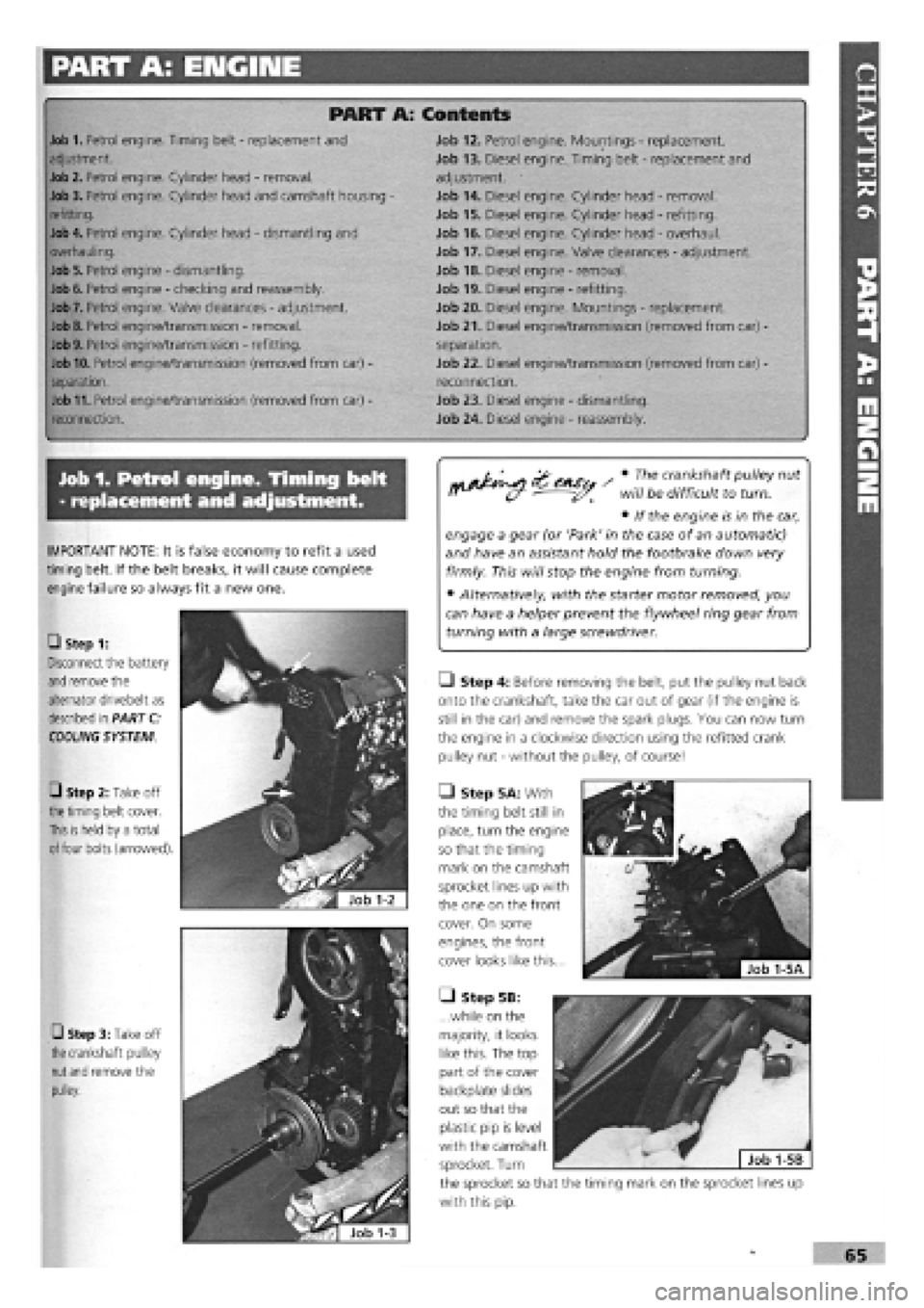
Job 1. Petrol engine. Timing belt
- replacement and adjustment.
Mi*^^ Zc+sc, / • The crankshaft pulley nut
n^^ will be difficult to turn.
• If the engine is in the car,
engage a gear (or 'Park' in the case of an automatic)
and have an assistant hold the footbrake down very
firmly. This will stop the engine from turning.
• Alternatively, with the starter motor removed, you
can have a helper prevent the flywheel ring gear from
turning with a large screwdriver.
• Step 4: Before removing the belt, put the pulley nut back
onto the crankshaft, take the car out of gear (if the engine is
still in the car) and remove the spark plugs. You can now turn
the engine in a clockwise direction using the refitted crank
pulley nut
-
without the pulley, of course!
• Step 5A: With
the timing belt still in
place, turn the engine
so that the timing
mark on the camshaft
sprocket lines up with
the one on the front
cover. On some
engines, the front
cover looks like this...
• Step 5B:
...while on the
majority, it looks
like this. The top
part of the cover
backplate slides
out so that the
plastic pip is level
with the camshaft
sprocket. Turn
the sprocket so that the timing mark on the sprocket lines up
with this pip.
IMPORTANT NOTE: It is false economy to refit a used
timing belt. If the belt breaks, it will cause complete
engine failure so always fit a new one.
• Step 1:
Disconnect the battery
and
remove the
alternator drivebelt as
described in PART C:
COOLING
SYSTEM
0 Step 2: Take off
the timing
belt cover.
This is held
by a total
of
four bolts (arrowed).
• Step 3: Take off
the
crankshaft pulley
nut and
remove the
pulley.
Page 62 of 171
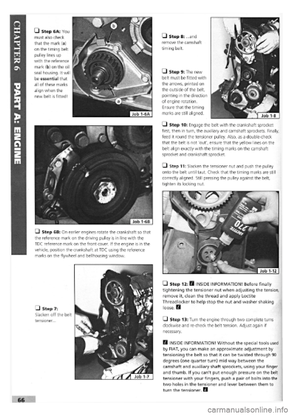
• Step 6A: You
must also check
that the mark (a)
on the timing belt
pulley lines up
with the reference
mark (b) on the oil
seal housing. It will
be essential that
all of these marks
align when the
new belt is fitted!
Q Step 6B: On earlier engines rotate the crankshaft so that
the reference mark on the driving pulley is in line with the
TDC reference mark on the front cover. If the engine is in the
vehicle, position the crankshaft at TDC using the reference
marks on the flywheel and bellhousing window.
• Step 7:
Slacken off the belt
tensioner...
• Step 8: ...and
remove the camshaft
timing belt.
Q Step 9: The new
belt must be fitted with
the arrows, printed on
the outside of the belt,
pointing in the direction
of engine rotation.
Ensure that the timing
marks are still aligned.
• Step 10: Engage the belt with the crankshaft sprocket
first, then in turn, the auxiliary and camshaft sprockets. Finally,
feed it round the tensioner pulley. Also, as a double-check
that the belt is not 'out', ensure that the yellow lines on the
belt align exactly with the timing marks on the camshaft
sprocket and crankshaft sprocket.
Q Step 11: Slacken the tensioner nut and push the pulley
onto the belt until taut. Check that the timing marks are still
correctly aligned. Still pressing the pulley against the belt,
tighten its locking nut.
• Step 12: H INSIDE INFORMATION! Before finally
tightening the tensioner nut when adjusting the tension,
remove it, clean the thread and apply Loctite
Threadlocker to help stop the nut and washer shaking
loose. Q
Q Step 13: Turn the engine through two complete turns
clockwise and re-check the belt tension. Adjust again if
necessary.
Q INSIDE INFORMATION! Without the special tools used
by FIAT, you can make an approximate adjustment by
tensioning the belt so that it can be twisted through 90
degrees (one quarter turn) mid way between the
camshaft and auxiliary shaft sprockets, using your finger
and thumb. If you can't put enough pressure on the belt
tensioner with your fingers, push a pair of bolts into the
two holes in the tensioner and lever between them to
turn the tensioner. B
Page 63 of 171
Job 2. Petrol engine. Cylinder
head • removal.
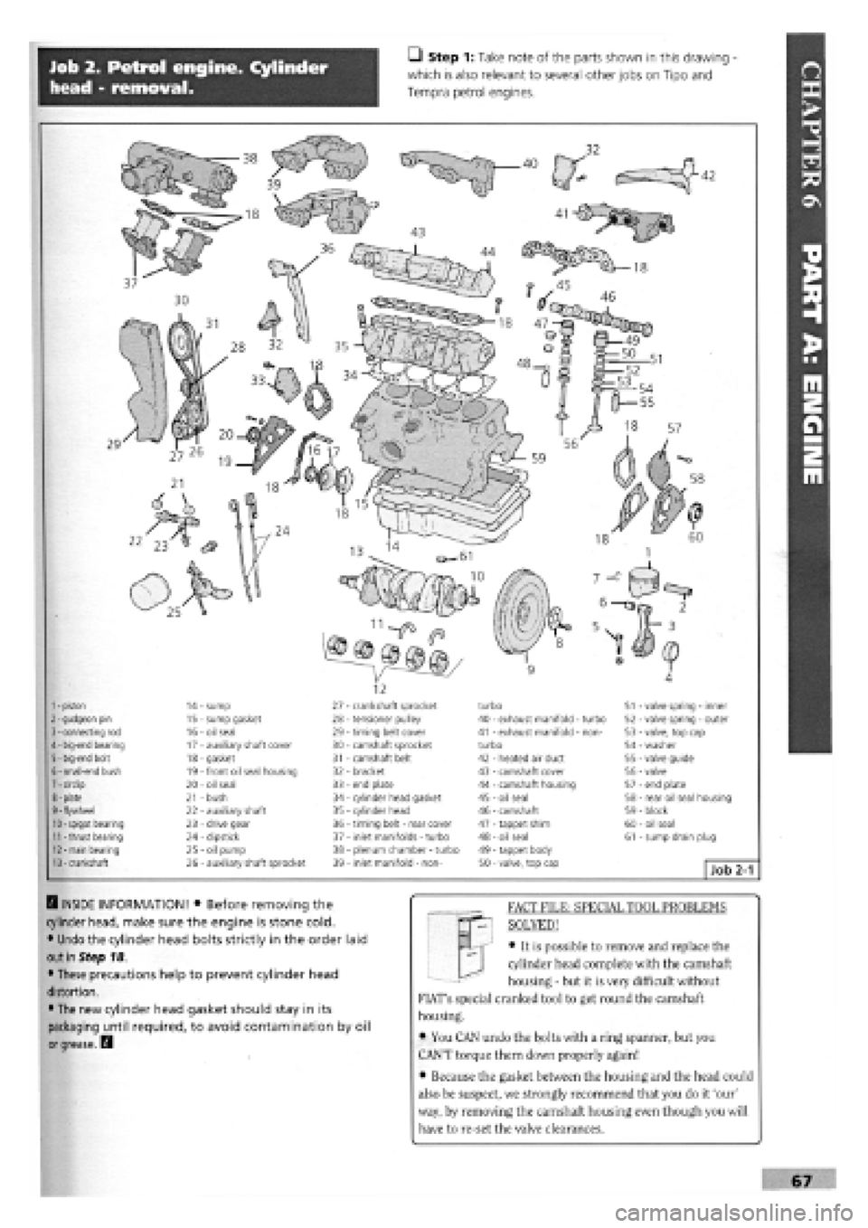
• Step 1: Take note of the parts shown in this drawing -
which is also relevant to several other jobs on Tipo and
Tempra petrol engines.
7
-
cirdip 8
-
plate 9
-
flywheel 10-spigot bearing
11 -
thrust bearing 12
-
main bearing 13-crankshaft
14 - sump 15 - sump gasket 16 - oil seal 17 - auxiliary shaft cover 18 - gasket 19 - front oil seal housing 20 - oil seal 21 - bush 22 - auxiliary shaft 23 - drive gear 24 - dipstick 25 - oil pump 26 - auxiliary shaft sprocket
1
-
piston 2
-
gudgeon pin 3
-
connecting rod 4
-
big-end bearing 5
-
big-end bolt 6
-
small-end bush
27 28 29 30 31 32 33 34 35 36 37 38 39
turbo 40 - exhaust manifold - turbo 41 - exhaust manifold - non-turbo 42 - heated air duct 43 - camshaft cover 44 - camshaft housing 45 - oil seal 46 - camshaft 47 - tappet shim 48 - oil seal 49 - tappet body 50
-
valve, top cap Job 2-1
- crankshaft sprocket - tensioner pulley - timing belt cover - camshaft sprocket - camshaft belt - bracket - end plate - cylinder head gasket - cylinder head - timing belt - rear cover - inlet manifolds - turbo - plenum chamber
-
turbo - inlet manifold - non-
51 - valve spring - inner 52 - valve spring
-
outer 53 - valve, top cap 54 - washer 55 - valve guide 56 - valve 57 - end plate 58 - rear oil seal housing 59 - block 60 - oil seal 61 - sump drain plug
Q INSIDE INFORMATION! • Before removing the
cylinder head, make sure the engine is stone cold.
• Undo the cylinder head bolts strictly in the order laid
out in Step 18.
• These precautions help to prevent cylinder head
distortion.
• The new cylinder head gasket should stay in its
packaging until required, to avoid contamination by oil
or grease.
B
FACT FILE: SPECIAL TOOL PROBLEMS
SOLVED!
• It is possible to remove and replace the
cylinder head complete with the camshaft
housing - but it is very difficult without
FIAT's special cranked tool to get round the camshaft
housing.
• You CAN undo the bolts with a ring spanner, but you
CAN'T torque them down properly again!
• Because the gasket between the housing and the head could
also be suspect, we strongly recommend that you do it 'our'
way, by removing the camshaft housing even though you will
have to re-set the valve clearances.
Page 64 of 171
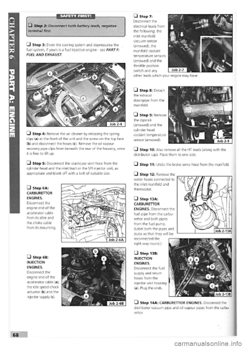
SAFETY FIRST! • Step 7:
Disconnect the
electrical leads from
the following: the
inlet manifold
• Step 2: Disconnect both battery leads, negative
terminal first.
Q Step 3: Drain the cooling system and depressurise the
fuel system, if yours is a fuel injection engine
-
see PART
F:
FUEL AND EXHAUST
• Step 6B:
INJECTION
ENGINES.
Disconnect the
engine end of the
accelerator cable (a),
the idle speed check
actuator (b) and the
injector supply (c).
• Step 8: Detach
the exhaust
downpipe from the
manifold.
• Step 9: Remove
the dipstick
(arrowed) and the
cylinder head
coolant temperature
sensor (arrowed).
• Step 10: Also remove all the HT leads (along with the
distributor cap). Place them to one side.
• Step 11: Undo the brake servo hose from the manifold.
Q Step 4: Remove the air cleaner by releasing the spring
clips (a) at the front of the unit and the screw on the top face
(b) and disconnect the hoses
recovery pipe clips from beneath the rear of the housing, once
it is free to lift up.
Q Step 5: Disconnect the crankcase vent hose from the
cylinder head and the inlet tract or the SPI injector unit, as
appropriate and blank off with a bolt of suitable size.
• Step 6A:
CARBURETTOR
ENGINES.
Disconnect the
engine end of the
accelerator cable
from its idler and
the choke cable
from its mounting.
Q Step 12: Remove the
water hoses connected to
the inlet manifold and
thermostat.
• Step 13 A:
CARBURETTOR
ENGINES. Disconnect the
fuel pipe from the carbu-
rettor and both pipes
from the fuel pump.
(Label both the pipes and
stubs so that they will be
reconnected the
right way round.)
• Step 13B:
INJECTION
ENGINES.
Disconnect the fuel
supply and return
hoses from the
injector unit housing
(a). Plug the ends.
• Step 14A: CARBURETTOR ENGINES. Disconnect the
distributor vacuum pipe and oil vapour pipes from the carbu-
rettor.
vacuum sensor
(arrowed), the
manifold coolant
temperature sensors
(arrowed) and the
throttle position
switch and any
other leads which your engine may have.
Page 65 of 171
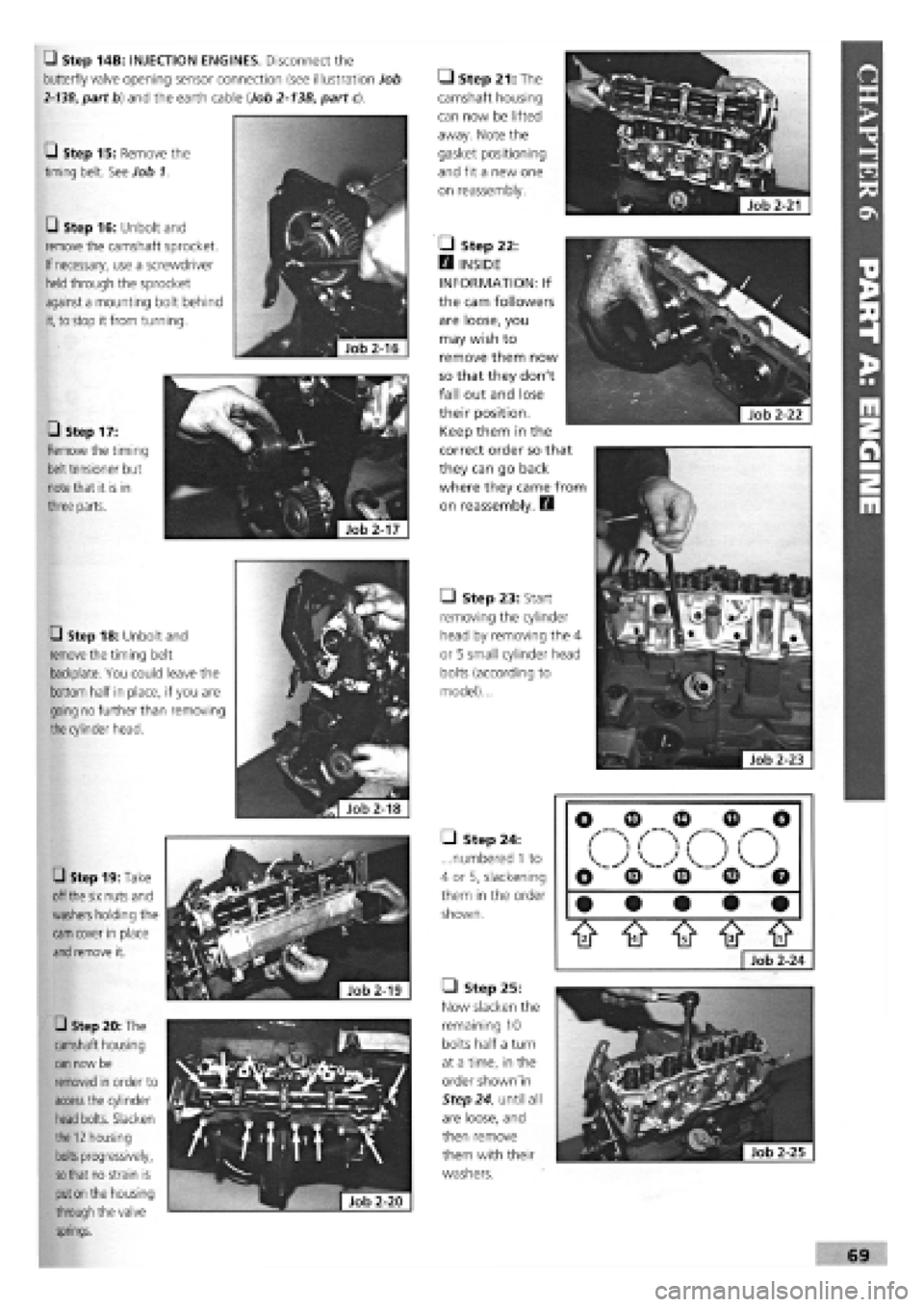
• Step 14B: INJECTION ENGINES. Disconnect the
butterfly valve opening sensor connection (see illustration Job
2-13B,
part b) and the earth cable (Job
2-13B,
part c).
Q Step 15: Remove the
timing belt. See Job 1.
• Step 16: Unbolt and
remove the camshaft sprocket.
If necessary, use a screwdriver
held
through the sprocket
against a mounting bolt behind
it,
to stop it from turning.
• Step 17:
Remove the timing
belt
tensioner but
note
that it is in
three parts.
• Step 18: Unbolt and
remove
the timing belt
backplate. You could leave the
bottom half in place, if you are
going no further than removing
the
cylinder head.
• Step 19: Take
off
the six
nuts and
washers
holding the
cam
cover in place
and
remove it.
• Step 20: The
camshaft housing
can
now be
removed in order to
access
the cylinder
head
bolts. Slacken
the
12
housing
bolts
progressively,
so that
no strain is
put on
the housing
through
the valve
springs.
Job
2-20
|
• Step 21: The
camshaft housing
can now be lifted
away. Note the
gasket positioning
and fit a new one
on reassembly.
• Step 22:
H INSIDE
INFORMATION: If
the cam followers
are loose, you
may wish to
remove them now
so that they don't
fall out and lose
their position.
Keep them in the
correct order so that
they can go back
where they came from
on reassembly. D
• Step 23: Start
removing the cylinder
head by removing the 4
or 5 small cylinder head
bolts (according to
model)...
^Hob^l]
• Step 24:
...numbered
1
to
4 or 5, slackening
them in the order
shown.
• Step 25:
Now slacken the
remaining 10
bolts half a turn
at a time, in the
order shown'in
Step 24, until all
are loose, and
then remove
them with their
washers.
ft ft ft ft tt
Job 2-24
Page 66 of 171
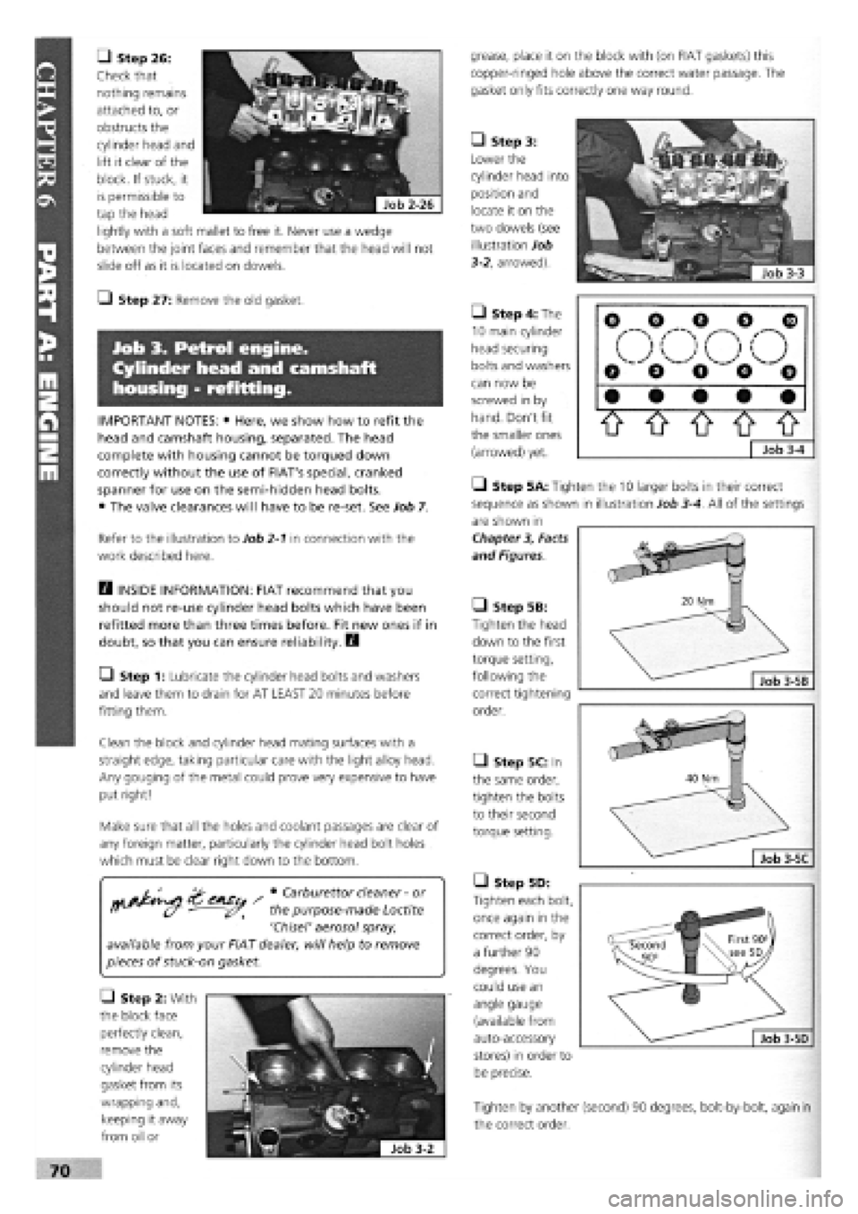
• Step 26:
Check that
nothing remains
attached to, or
obstructs the
cylinder head and
lift it clear of the
block. If stuck, it
is permissible to
tap the head
lightly with a soft mallet to free it. Never use a wedge
between the joint faces and remember that the head will not
slide off as it is located on dowels.
Job 3. Petrol engine.
Cylinder head and camshaft
housing - refitting.
• Carburettor cleaner
-
or
the purpose-made Loctite
'Chisel' aerosol spray,
available from your FIAT dealer, will help to remove
pieces of
stuck-on
gasket.
o
(
V.
o
o
o
o o o
o o e
• • • • •
0 0 O 0 o
Job
3-4
grease, place it on the block with (on FIAT gaskets) this
copper-ringed hole above the correct water passage. The
gasket only fits correctly one way round.
• Step 3:
Lower the
cylinder head into
position and
locate it on the
two dowels (see
illustration Job
3-2, arrowed).
Refer to the illustration to Job
2-1
in connection with the
work described here.
• Step 4: The
10 main cylinder
head securing
bolts and washers
can now be
screwed in by
hand. Don't fit
the smaller ones
(arrowed) yet.
Q INSIDE INFORMATION: FIAT recommend that you
should not re-use cylinder head bolts which have been
refitted more than three times before. Fit new ones if in
doubt, so that you can ensure reliability. B
• Step 1: Lubricate the cylinder head bolts and washers
and leave them to drain for AT LEAST 20 minutes before
fitting them.
• Step 5B:
Tighten the head
down to the first
torque setting,
following the
correct tightening
order.
Q Step 27: Remove the old gasket.
IMPORTANT NOTES: • Here, we show how to refit the
head and camshaft housing, separated. The head
complete with housing cannot be torqued down
correctly without the use of FIAT's special, cranked
spanner for use on the semi-hidden head bolts.
• The valve clearances will have to be re-set. See Job 7.
Clean the block and cylinder head mating surfaces with a
straight edge, taking particular care with the light alloy head.
Any gouging of the metal could prove very expensive to have
put right!
Make sure that all the holes and coolant passages are clear of
any foreign matter, particularly the cylinder head bolt holes
which must be clear right down to the bottom.
• Step 5C: In
the same order,
tighten the bolts
to their second
torque setting.
• Step 2: With
the block face
perfectly clean,
remove the
cylinder head
gasket from its
wrapping and,
keeping it away
from oil or
Tighten by another (second) 90 degrees, bolt-by-bolt, again in
the correct order.
• Step 5D:
Tighten each bolt,
once again in the
correct order, by
a further 90
degrees. You
could use an
angle gauge
(available from
auto-accessory
stores) in order to
be precise.
Q Step 5A: Tighten the 10 larger bolts in their correct
sequence as shown in illustration Job
3-4.
All of the settings
are shown in
Chapter
3,
Facts
and Figures.
Page 67 of 171
G Step 6: Fit the four or five smaller bolts, according to
model (see illustration Job
3-4,
arrowed) close to the spark
plug holes, and tighten to their specified torque. See Chapter
3, Facts
and Figures.
G Step 7: All items previously removed in Job 2 can now be
fitted in reverse order. When connecting the exhaust always
use a
new flange gasket.
G Step 8: Ensure that all connections are sound and secure.
G Step 9: All items previously removed in Job 2 can now be
fitted in reverse order. Refer to Job
1
when fitting the timing
belt.
When connecting the exhaust always use a new flange
gasket.
G Step 10: Ensure that all connections are sound and
secure.
G Step 11: Top up the cooling system with the correct
50/50
solution of FL 'Tutela' anti-freeze solution. Check the
oil
level.
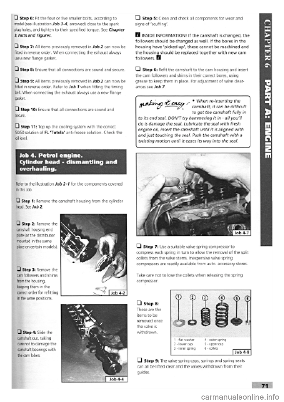
• Step 5: Clean and check all components for wear and
signs of 'scuffing'.
B INSIDE INFORMATION! If the camshaft is changed, the
followers should be changed as well. If the bores in the
housing have 'picked up', these cannot be machined and
the housing should be replaced together with new cam
followers. B
• Step 6: Refit the camshaft to the cam housing and insert
the cam followers and shims in their correct bores, using
grease to keep them in place. For adjustment of valve clear-
ances see Job 7.
2 ZeASt, s * when re'inserti"9the
nfW^c/ !X J?^ camshaft, it can be difficult
to get the camshaft fully in
to its end seal. DON'T try hammering it in
-
all you'll
do is damage the seal. Lubricate the seal with fresh
engine oil, insert the camshaft until it is aligned with
and just touching the seal. Push the camshaft with a
twisting motion until it eases its way into the seal.
Job 4. Petrol engine.
Cylinder head - dismantling and
overhauling.
G Step 3: Remove the
cam
followers and shims
from
the housing,
keeping them in the
correct order for refitting
in the
same positions.
Refer to the illustration Job
2-1
for the components covered
in this
Job.
G Step 1: Remove the camshaft housing from the cylinder
head. See Job 2.
G Step 2: Remove the
camshaft housing end
plate
(or the distributor
mounted in the same
place on
certain models).
G Step 4: Slide the
camshaft out, taking
care not to damage the
camshaft bearings with
the cam
lobes.
• Step 7: Use a suitable valve spring compressor to
compress each spring in turn to allow the removal of the split
collets from the valve stems. Inexpensive valve spring
compressors are readily available from auto, accessory stores.
Take care not to lose the collets when releasing the spring
compressor.
Q Step 9: The valve spring caps, springs and spring seats
can all be lifted clear and the valves withdrawn from their
guides.
• Step 8:
These are the
items to be
removed once
the valve is
withdrawn.
1 - flat washer 2 - lower cap 3 - inner spring
4 - outer spring 5 - upper cap 6 - collets Job 4-8
Page 68 of 171
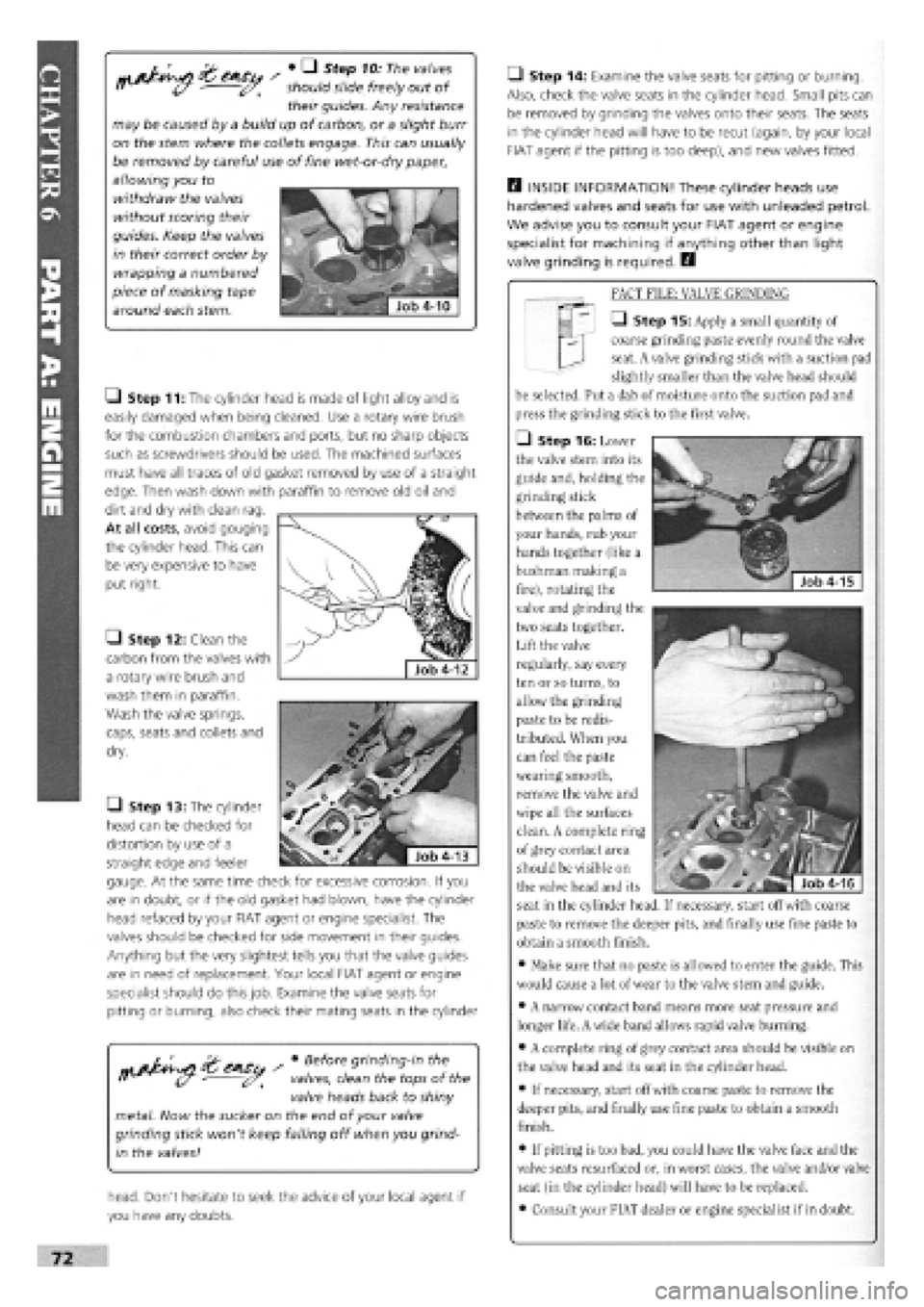
&CASU / # Q StGP 101 The ValV6S i* (/ should slide freely out of
their guides. Any resistance
may be caused by a build up of carbon, or a slight burr
on the stem where the collets engage. This can usually
be removed by careful use of fine wet-or-dry paper,
allowing you to
withdraw the valves
without scoring their
guides. Keep the valves
in their correct order by
wrapping a numbered
piece of masking tape
around each stem.
• Step 12: Clean the
carbon from the valves with
a rotary wire brush and
wash them in paraffin.
Wash the valve springs,
caps, seats and collets and
dry.
/ • Before grinding-in the
valves, clean the tops of the
valve heads back to shiny
metal. Now the sucker on the end of your valve
grinding stick won't keep falling off when you grind-
in the valves!
head. Don't hesitate to seek the advice of your local agent if
you have any doubts.
• Step 14: Examine the valve seats for pitting or burning.
Also, check the valve seats in the cylinder head. Small pits can
be removed by grinding the valves onto their seats. The seats
in the cylinder head will have to be recut (again, by your local
FIAT agent if the pitting is too deep), and new valves fitted.
B INSIDE INFORMATION! These cylinder heads use
hardened valves and seats for use with unleaded petrol.
We advise you to consult your FIAT agent or engine
specialist for machining if anything other than light
valve grinding is required. B
FACT FILE: VALVE GRINDING
• Step 15: Apply a small quantity of
coarse grinding paste evenly round the valve
seat. A valve grinding stick with a suction pad
slightly smaller than the valve head should
be selected. Put a dab of moisture onto the suction pad and
press the grinding stick to the first valve.
• Step 16: Lower
the valve stem into its
guide and, holding the
grinding stick
between the palms of
your hands, rub your
hands together (like a
bushman making a
fire), rotating the
valve and grinding the
two seats together.
Lift the valve
regularly, say every
ten or so turns, to
allow the grinding
paste to be redis-
tributed. When you
can feel the paste
wearing smooth,
remove the valve and
wipe all the surfaces
clean. A complete ring
of grey contact area
should be visible on
the valve head and its
seat in the cylinder head. If necessary, start off with coarse
paste to remove the deeper pits, and finally use fine paste to
obtain a smooth finish.
• Make sure that no paste is allowed to enter the guide. This
would cause a lot of wear to the valve stem and guide.
• A narrow contact band means more seat pressure and
longer life. A wide band allows rapid valve burning.
• A complete ring of grey contact area should be visible on
the valve head and its seat in the cylinder head.
• If necessary, start off with coarse paste to remove the
deeper pits, and finally use fine paste to obtain a smooth
finish.
• If pitting is too bad, you could have the valve face and the
valve seats resurfaced or, in worst cases, the valve and/or valve
seat (in the cylinder head) will have to be replaced.
• Consult your FIAT dealer or engine specialist if in doubt.
LJ Step 11: The cylinder head is made of light alloy and is
easily damaged when being cleaned. Use a rotary wire brush
for the combustion chambers and ports, but no sharp objects
such as screwdrivers should be used. The machined surfaces
must have all traces of old gasket removed by use of a straight
edge. Then wash down with paraffin to remove old oil and
dirt and dry with clean rag.
At all costs, avoid gouging
the cylinder head. This can
be very expensive to have
put right.
• Step 13: The cylinder
head can be checked for
distortion by use of a
straight edge and feeler
gauge. At the same time check for excessive corrosion. If you
are in doubt, or if the old gasket had blown, have the cylinder
head refaced by your FIAT agent or engine specialist. The
valves should be checked for side movement in their guides.
Anything but the very slightest tells you that the valve guides
are in need of replacement. Your local FIAT agent or engine
specialist should do this job. Examine the valve seats for
pitting or burning, also check their mating seats in the cylinder
72
Page 69 of 171
G Step 17: Now repeat this operation on the remaining
valves.
G Step 18: Wash the whole cylinder head again using
paraffin and an old brush, making sure that all traces of
grinding paste are removed, then dry off. Use compressed air
if
available.
SAFETY FIRST!
•
Treat
compressed air with respect. Always wear
goggles
to protect your eyes.
•
Never
allow the airline nozzle near any of the body Sep apertures.
H INSIDE INFORMATION! Check the height of the valve
springs against new ones if possible, but if not, compare
them with each other. If any are shorter than the others,
play safe and replace the complete set. They are bound
to have suffered fatigue which could cause premature
valve failure. H
G Step 19: To install the valves, start from one end.
Lubricate a valve stem with fresh engine oil and slide it in to its
guide.
G Step 20: Locate a new valve stem seal over the stem of
the valve
(if applicable) and push down into contact with the
guide. Position the seal on its seat using a suitable metal tube.
G Step 21: Refit the flat washer and spring seat.
G Step 22: Position the inner and outer springs and the
spring
cap.
G Step 23: Re-apply the valve spring compressor and
compress
the springs enough to allow you to engage the split
collets
in
the stem grooves.
D INSIDE INFORMATION! Grease the grooves so that the
collets will 'stick' in place. The collets are easily fitted by
'sticking' the backs of them onto the end of a screw-
driver with some grease and feeding them into
position. B
G Step 24: Carefully release the spring compressor and
check
that the collets are correctly located. Tap the end of the
stem with
a hammer, to bed them in.
G Step 25: Fit the remaining valves.
Job 5. Petrol engine -
dismantling.
G Step 1: Familiarise yourself with the layout of the engine.
Refer to
illustration Job
2-1
for an exploded view of the
engine
components.
G Step 2: Drain the engine oil. Remove the cylinder head.
See
Job 2.
G Step 3: Remove the distributor. See PART D: IGNITION
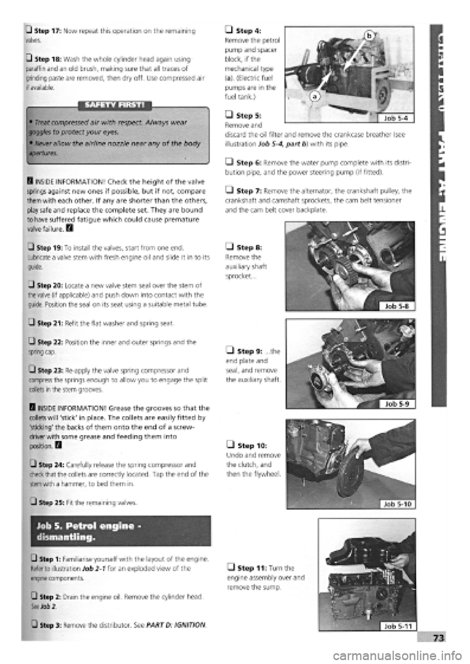
• Step 4:
Remove the petrol
pump and spacer
block, if the
mechanical type
(a). (Electric fuel
pumps are in the
fuel tank.)
• Step 5:
Remove and
discard the oil filter
illustration Job
5-4,
• Step 6: Remove the water pump complete with its distri-
bution pipe, and the power steering pump (if fitted).
Q Step 7: Remove the alternator, the crankshaft pulley, the
crankshaft and camshaft sprockets, the cam belt tensioner
and the cam belt cover backplate.
• Step 8:
Remove the
auxiliary shaft
sprocket...
• Step 9: ...the
end plate and
seal, and remove
the auxiliary shaft.
• Step 10:
Undo and remove
the clutch, and
then the flywheel.
• Step 11: Turr
engine assembly c
remove the sump
and remove the crankcase breather (see
part b) with its pipe.
Page 70 of 171
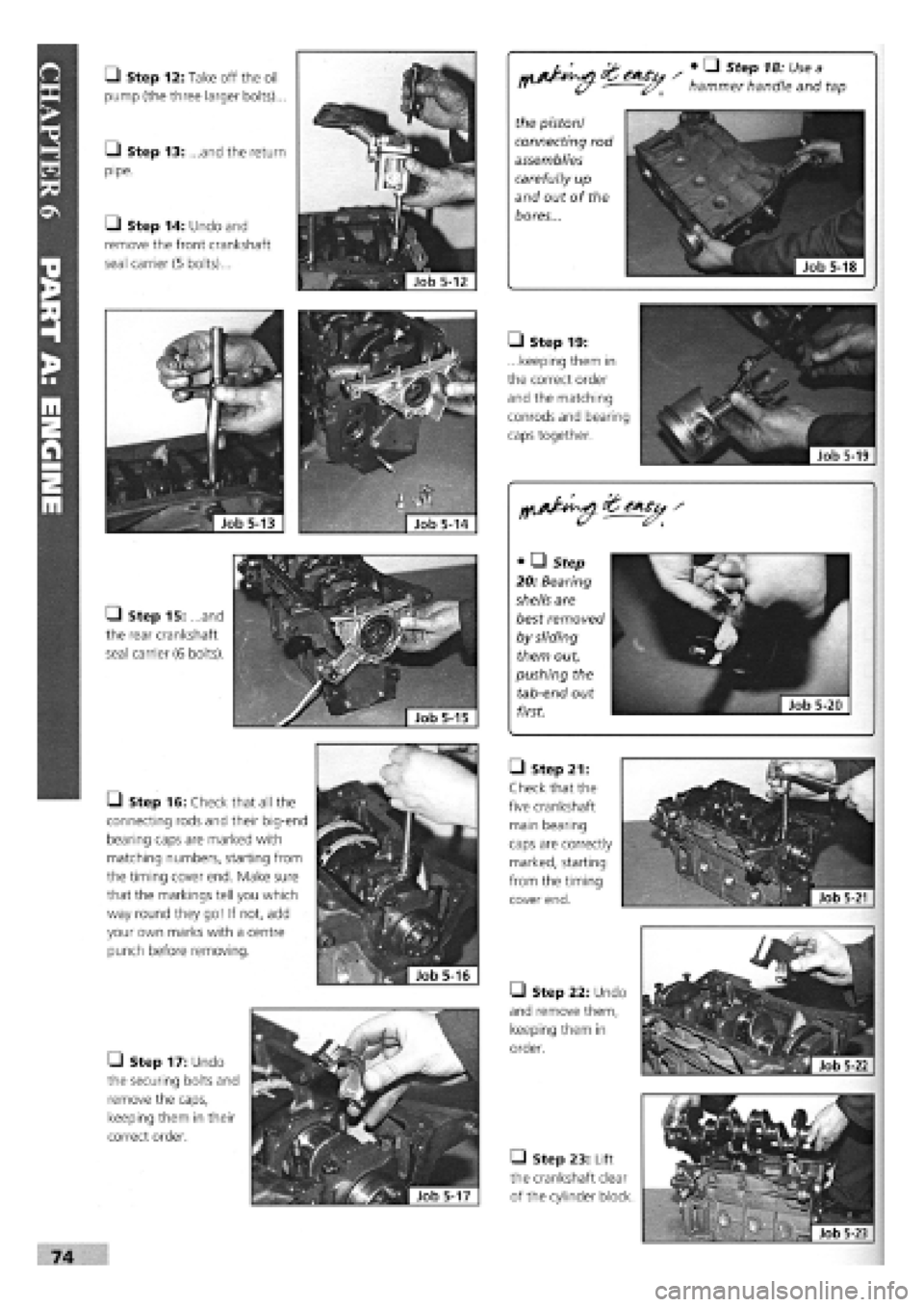
• Step 12: Take off the oil
pump (the three larger bolts)...
• Step 13: ...and the return
pipe.
• Step 14: Undo and
remove the front crankshaft
seal carrier (5 bolts)...
hammer handle and tap
the piston/
connecting rod
assemblies
carefully up
and out of the
bores...
• Step 15: and
the rear crankshaft
seal carrier (6 bolts).
• Step 19:
...keeping them in
the correct order
and the matching
conrods and bearing
caps together.
• • Step
20: Bearing
shells are
best removed
by sliding
them out,
pushing the
tab-end out
first.
• Step 16: Check that all the
connecting rods and their big-end
bearing caps are marked with
matching numbers, starting from
the timing cover end. Make sure
that the markings tell you which
way round they go! If not, add
your own marks with a centre
punch before removing.
• Step 22: Undo
and remove them,
keeping them in
order.
• Step 23: Lift
the crankshaft clear
of the cylinder block.
• Step 17: Undo
the securing bolts and
remove the caps,
keeping them in their
correct order.
• Step 21:
Check that the
five crankshaft
main bearing
caps are correctly
marked, starting
from the timing
cover end.