FIAT TEMPRA 1988 Service And Manual Online
Manufacturer: FIAT, Model Year: 1988, Model line: TEMPRA, Model: FIAT TEMPRA 1988Pages: 171, PDF Size: 18.05 MB
Page 81 of 171
Job 13. Diesel engine. Timing belt
- replacement and adjustment.
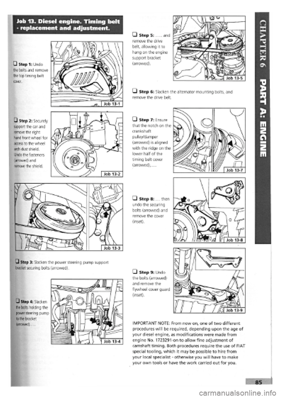
• Step 1: Undo
the bolts and remove
the
top timing belt
cover.
Q Step 2: Securely
support the car and
remove
the right
hand
front wheel for
access
to the wheel
arch
dust shield.
Undo
the fasteners
(arrowed) and
remove
the shield.
• Step 3: Slacken the power steering pump support
bracket securing
bolts (arrowed).
Q Step 4: Slacken
the bolts
holding the
power steering
pump
to the
bracket
(arrowed)
• Step 5: and
remove the drive
belt, allowing it to
hang on the engine
support bracket
(arrowed).
• Step 6: Slacken the alternator mounting bolts, and
remove the drive belt.
• Step 7: Ensure
that the notch on the
crankshaft
pulley/damper
(arrowed) is aligned
with the ridge on the
lower half of the
timing belt cover
(arrowed),
M
V// Job 13-7
• Step 8: .... then
undo the securing
bolts (arrowed) and
remove the cover
(inset).
• Step 9: Undo
the bolts (arrowed)
and remove the
flywheel cover guard
(inset).
IMPORTANT NOTE: From now on, one of two different
procedures will be required, depending upon the age of
your diesel engine, as modifications were made from
engine No. 1723291-on to allow fine adjustment of
camshaft timing. Both procedures require the use of FIAT
special tooling, which it may be possible to hire from
your local specialist
-
otherwise you will have to make
your own tools or have the work carried out for you.
85
Page 82 of 171
PART A
-
ENGINES PRIOR TO ENGINE NO. 1723291 • Step A15: Ease the timing belt off the sprockets.
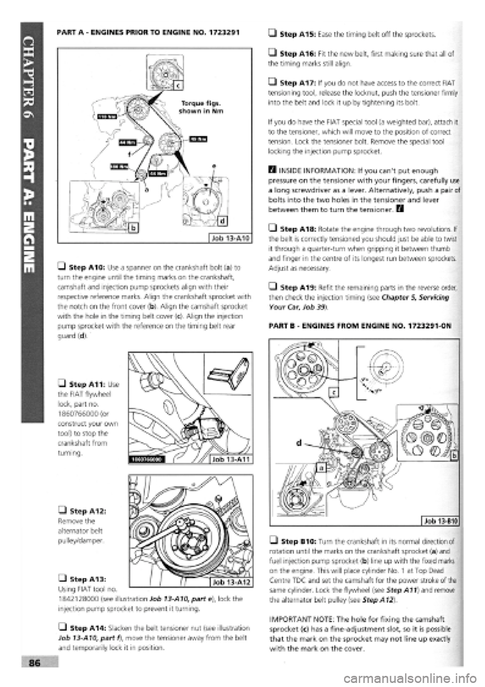
Gl Step A10: Use a spanner on the crankshaft bolt (a) to
turn the engine until the timing marks on the crankshaft,
camshaft and injection pump sprockets align with their
respective reference marks. Align the crankshaft sprocket with
the notch on the front cover (b). Align the camshaft sprocket
with the hole in the timing belt cover (c). Align the injection
pump sprocket with the reference on the timing belt rear
guard (d).
• Step A11: Use
the FIAT flywheel
lock, part no.
1860766000 (or
construct your own
tool) to stop the
crankshaft from
turning.
• Step A12:
Remove the
alternator belt
pulley/damper.
• Step A13:
Using FIAT tool no.
1842128000 (see illustration Job
13-A10,
parte), lock the
injection pump sprocket to prevent it turning.
• Step A14: Slacken the belt tensioner nut (see illustration
Job
13-A10,
part f), move the tensioner away from the belt
and temporarily lock it in position.
• Step A16: Fit the new belt, first making sure that all of
the timing marks still align.
• Step A17: If you do not have access to the correct FIAT
tensioning tool, release the locknut, push the tensioner firmly
into the belt and lock it up by tightening its bolt.
If you do have the FIAT special tool (a weighted bar), attach it
to the tensioner, which will move to the position of correct
tension. Lock the tensioner bolt. Remove the special tool
locking the injection pump sprocket.
E3 INSIDE INFORMATION: If you can't put enough
pressure on the tensioner with your fingers, carefully use
a long screwdriver as a lever. Alternatively, push a pair of
bolts into the two holes in the tensioner and lever
between them to turn the tensioner. E9
Q Step A18: Rotate the engine through two revolutions. If
the belt is correctly tensioned you should just be able to twist
it through a quarter-turn when gripping it between thumb
and finger in the centre of its longest run between sprockets.
Adjust as necessary.
Q Step A19: Refit the remaining parts in the reverse order,
then check the injection timing (see Chapter
5,
Servicing
Your Car, Job
39)
PART B
-
ENGINES FROM ENGINE NO. 1723291-ON
Job 13-B10
Q Step B10: Turn the crankshaft in its normal direction of
rotation until the marks on the crankshaft sprocket (a) and
fuel injection pump sprocket (b) line up with the fixed marks
on the engine. This will place cylinder No. 1 at Top Dead
Centre TDC and set the camshaft for the power stroke of the
same cylinder. Lock the flywheel (see Step A11) and remove
the alternator belt pulley (see Step A12).
IMPORTANT NOTE: The hole for fixing the camshaft
sprocket (c) has a fine-adjustment slot, so it is possible
that the mark on the sprocket may not line up exactly
with the mark on the cover.
Page 83 of 171
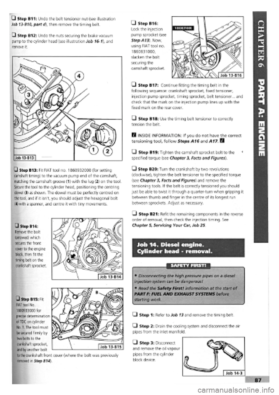
Q Step B11: Undo the belt tensioner nut (see illustration
Job 13-B10, part d), then remove the timing belt.
Q Step B12: Undo the nuts securing the brake vacuum
pump to the cylinder head (see illustration Job
16-1),
and
remove it.
• Step B13: Fit FIAT tool no. 1860932000 (for setting
camshaft timing) to the vacuum pump end of the camshaft,
matching the camshaft groove (1) with the lug (2) on the tool
Secure
the tool to the cylinder head, positioning the centring
dowel
(3) as shown. The dowel must be perfectly centred on
the tool,
and if it isn't, you should adjust the hexagonal bolt
(4) with
a spanner, and centre it with tiny movements.
• Step B14:
Remove
the bolt
(arrowed) which
secures
the front
cover
to the engine
block,
then fit the
timing belt on the
crankshaft sprocket.
• Step B16:
Lock the injection
pump sprocket (see
StepA13). Now,
using FIAT tool no.
1860831000,
slacken the bolt
securing the
camshaft sprocket.
• Step B17: Continue fitting the timing belt in the
following sequence: crankshaft sprocket, fixed tensioner,
injection pump sprocket, timing sprocket, belt tensioner... and
check that the mark on the injection pump lines up with the
fixed mark on the rear cover.
• Step B18: Use the timing belt tensioner to correctly
tension the belt.
B INSIDE INFORMATION: If you do not have the correct
tensioning tool, follow Steps A16 and A17. B
• Step B19: Tighten the camshaft sprocket bolt to the 1
specified torque (see Chapter
3,
Facts and Figures).
Q Step B20: Turn the crankshaft by two revolutions
(clockwise), tighten the belt tensioner to the specified torque
(see Chapter
3,
Facts and Figures) and remove the
tensioning tools. If the belt is correctly tensioned you should
just be able to twist it through a quarter-turn when gripping it
between thumb and finger in the centre of its longest run
between sprockets. Adjust as necessary.
O Step B21: Refit the remaining components in the reverse
order of removal, then check the injection timing. See
Chapter
5,
Servicing Your Car, Job 25.
Job 14. Diesel engine.
Cylinder head - removal.
• Disconnecting the high pressure pipes on a diesel
injection system can be dangerous!
• Read the Safety First! information at the start of
PART F: FUEL AND EXHAUST SYSTEMS before
starting work.
Q Step 1: Refer to Job
13
and remove the timing belt.
• Step 2: Drain the cooling system and disconnect the air
pipes from the inlet manifold.
Q Step 3: Disconnect
and remove the oil vapour
pipes from the cylinder
block device.
Job 13-B13
• Step B15: Fit
FIAT tool
No.
1860933000 for
precise
determination
of TDC
on cylinder
No. 1. The
tool must
be secured
firmly by
two bolts
to the
crankshaft sprocket,
and by
another bolt
to the
crankshaft front cover (where the bolt was previously
removed in Step B14).
Page 84 of 171
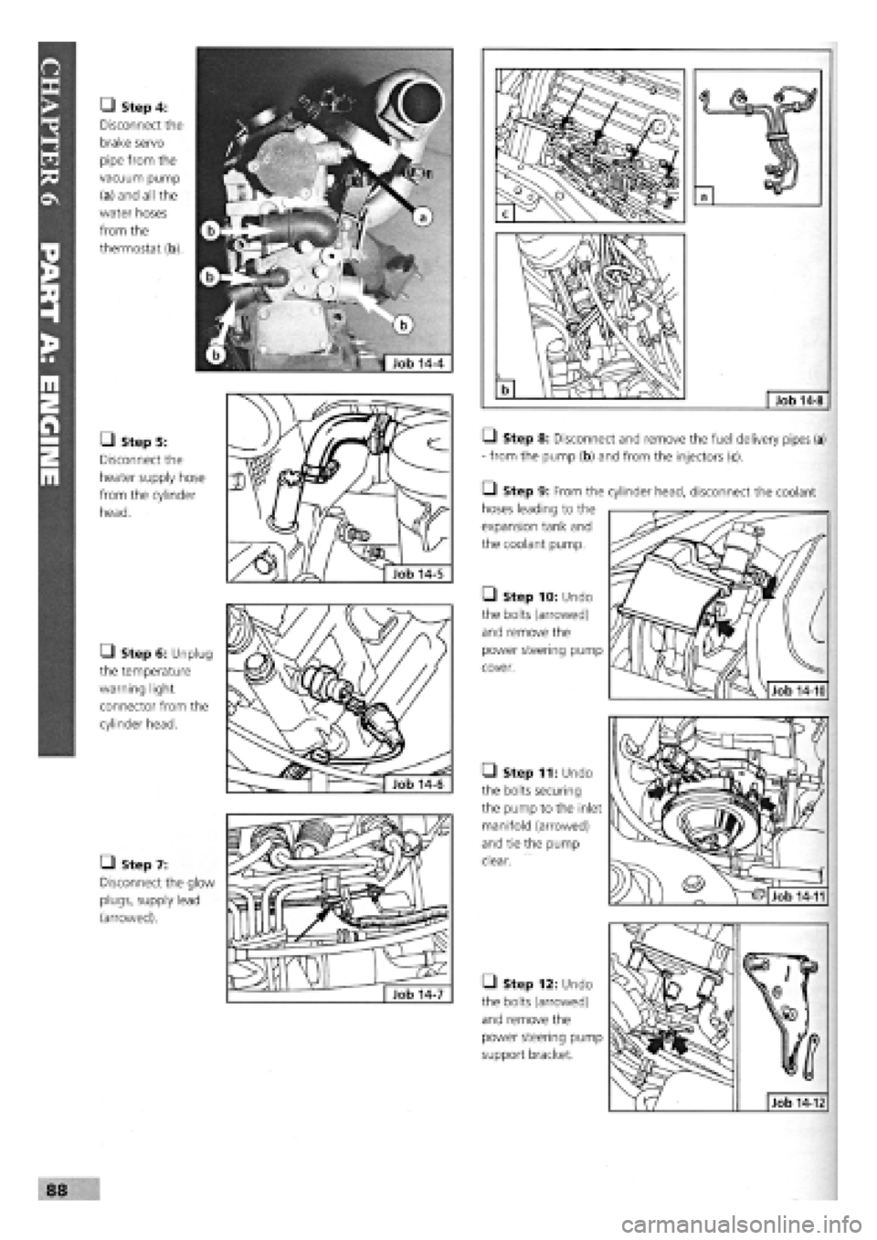
• Step 4:
Disconnect the
brake servo
pipe from the
vacuum pump
(a) and all the
water hoses
from the
thermostat (b).
• Step 5:
Disconnect the
heater supply hose
from the cylinder
head.
• Step 6: Unplug
the temperature
warning light
connector from the
cylinder head.
• Step 7:
Disconnect the glow
plugs, supply lead
(arrowed).
Q Step 8: Disconnect and remove the fuel delivery pipes (a)
- from the pump (b) and from the injectors (c).
• Step 9: From the
hoses leading to the
expansion tank and
the coolant pump.
• Step 10: Undo
the bolts (arrowed)
and remove the
power steering pump
cover.
• Step 11: Undo
the bolts securing
the pump to the inlet
manifold (arrowed)
and tie the pump
clear.
• Step 12: Undo
the bolts (arrowed)
and remove the
power steering pump
support bracket.
88
cylinder head, disconnect the coolant
Job 14-10
Job 14-12
Job 14-11
Page 85 of 171
SAFETY FIRST!
• The cylinder head is heavy and should be lifted from
the engine bay by two people.
Job 15. Diesel engine.
Cylinder head - refitting.
• Step 1: Put the
pistons at TDC
-
two
at a time
-
and
measure how much
they protrude above
the block surface.
This is ideally done
using a dial gauge
and holder (FIAT tools
1895882000 and
1870404000, respec-
tively) but if surfaces
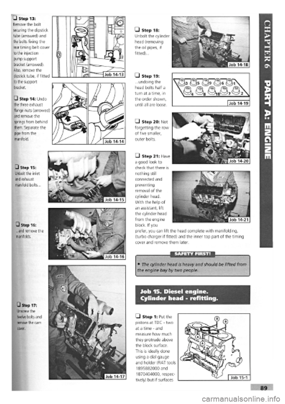
• Step 15:
Unbolt the inlet
and
exhaust
manifold bolts...
• Step 16:
...and remove the
manifolds.
• Step 17:
Unscrew the
twelve bolts
and
remove
the cam
cover.
• Step 18:
Unbolt the cylinder
head (removing
the oil pipes, if
fitted)...
• Step 20: Not
forgetting the row
of five smaller,
outer bolts.
• Step 13:
Remove the bolt
securing the dipstick
tube (arrowed) and
the bolts fixing the
rear timing belt cover
to
the injection
pump support
bracket (arrowed).
Also, remove the
dipstick tube, if fitted
to the
support
bracket.
• Step 14: Undo
the
three exhaust
flange nuts (arrowed)
and
remove the
springs
from behind
them. Separate the
pipe from
the
manifold.
• Step 19:
...undoing the
head bolts half a
turn at a time, in
the order shown,
until all are loose. Job 14-19
• Step 21: Have
a good look to
check that there is
nothing still
connected and
preventing
removal of the
cylinder head.
With the help of
an assistant, lift
the cylinder head
from the engine
block. If you
prefer, you can lift the head complete with manifolding,
(turbo charger if fitted) and the inner top part of the timing
cover and remove them later.
Page 86 of 171
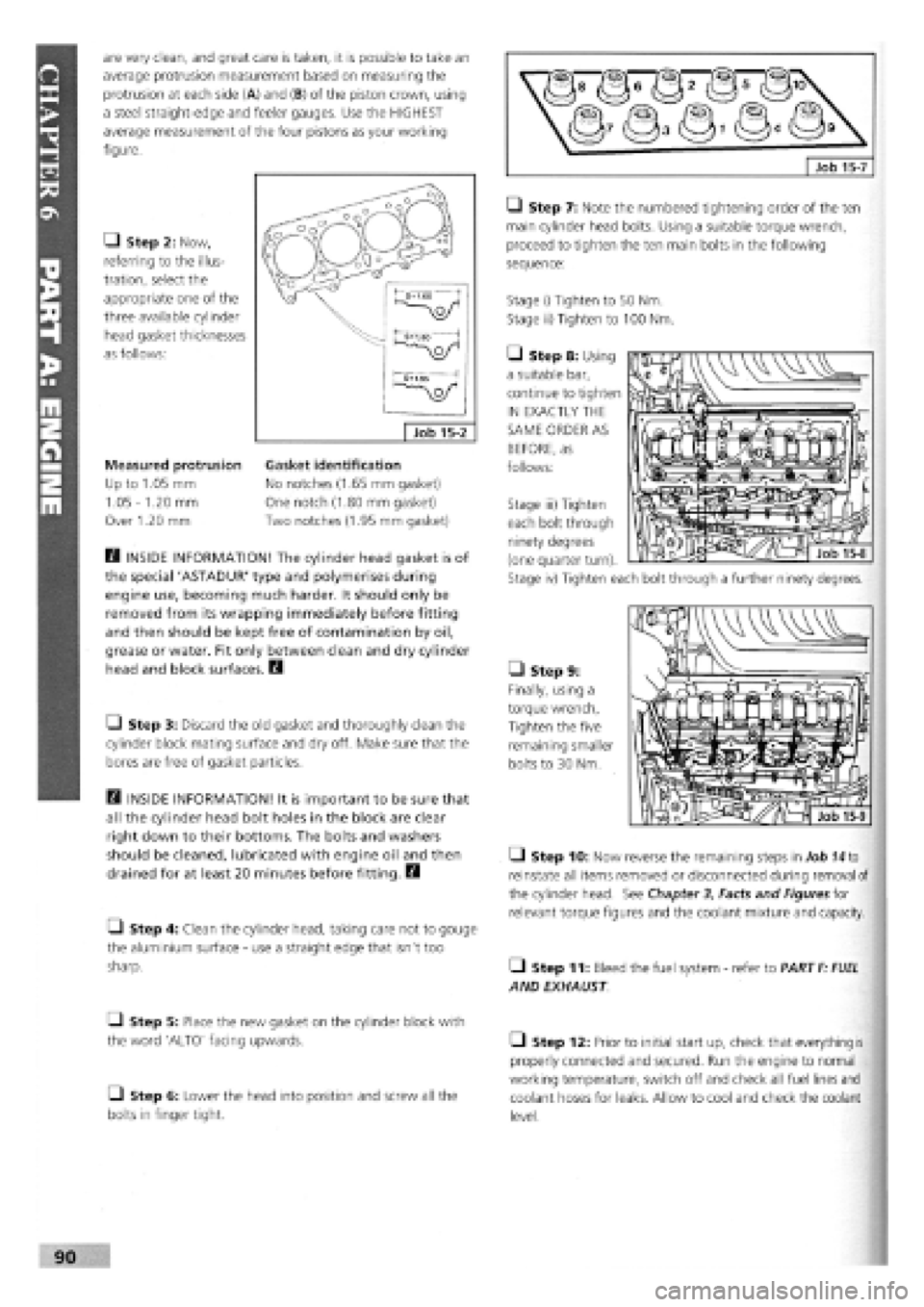
are very clean, and great care is taken, it is possible to take an
average protrusion measurement based on measuring the
protrusion at each side (A) and (B) of the piston crown, using
a steel straight-edge and feeler gauges. Use the HIGHEST
average measurement of the four pistons as your working
figure.
Q Step 2: Now,
referring to the illus-
tration, select the
appropriate one of the
three available cylinder
head gasket thicknesses
as follows:
Measured protrusion
Up to 1.05 mm
1.05
-
1.20 mm
Over 1.20 mm
B INSIDE INFORMATION! The cylinder head gasket is of
the special 'ASTADUR' type and polymerises during
engine use, becoming much harder. It should only be
removed from its wrapping immediately before fitting
and then should be kept free of contamination by oil,
grease or water. Fit only between clean and dry cylinder
head and block surfaces. B
• Step 3: Discard the old gasket and thoroughly clean the
cylinder block mating surface and dry off. Make sure that the
bores are free of gasket particles.
B INSIDE INFORMATION! It is important to be sure that
all the cylinder head bolt holes in the block are clear
right down to their bottoms. The bolts and washers
should be cleaned, lubricated with engine oil and then
drained for at least 20 minutes before fitting. B
• Step 4: Clean the cylinder head, taking care not to gouge
the aluminium surface
-
use a straight edge that isn't too
sharp.
Q Step 5: Place the new gasket on the cylinder block with
the word 'ALTO' facing upwards.
• Step 6: Lower the head into position and screw all the
bolts in finger tight.
LI Step 7: Note the numbered tightening order of the ten
main cylinder head bolts. Using a suitable torque wrench,
proceed to tighten the ten main bolts in the following
sequence:
Stage i) Tighten to 50 Nm.
Stage ii) Tighten to 100 Nm.
• Step 8: Using
a suitable bar,
continue to tighten
IN EXACTLY THE
SAME ORDER AS
BEFORE, as
follows:
• Step 9:
Finally, using a
torque wrench,
Tighten the five
remaining smaller
bolts to 30 Nm.
Q Step 10: Now reverse the remaining steps in Job
74
to
reinstate all items removed or disconnected during removal of
the cylinder head. See Chapter
3,
Facts and Figures for
relevant torque figures and the coolant mixture and capacity.
• Step 11: Bleed the fuel system
-
refer to PART
F: FUEL
AND EXHAUST
• Step 12: Prior to initial start up, check that everything is
properly connected and secured. Run the engine to normal
working temperature, switch off and check all fuel lines and
coolant hoses for leaks. Allow to cool and check the coolant
level.
Gasket identification
No notches (1.65 mm gasket)
One notch (1.80 mm gasket)
Two notches (1.95 mm gasket)
Stage iii) Tighten
each bolt through
ninety degrees
(one quarter turn).
Stage iv) Tighten each bolt through a further ninety degrees.
Page 87 of 171
Job 16. Diesel engine.
Cylinder head - overhaul.
Job 16-1
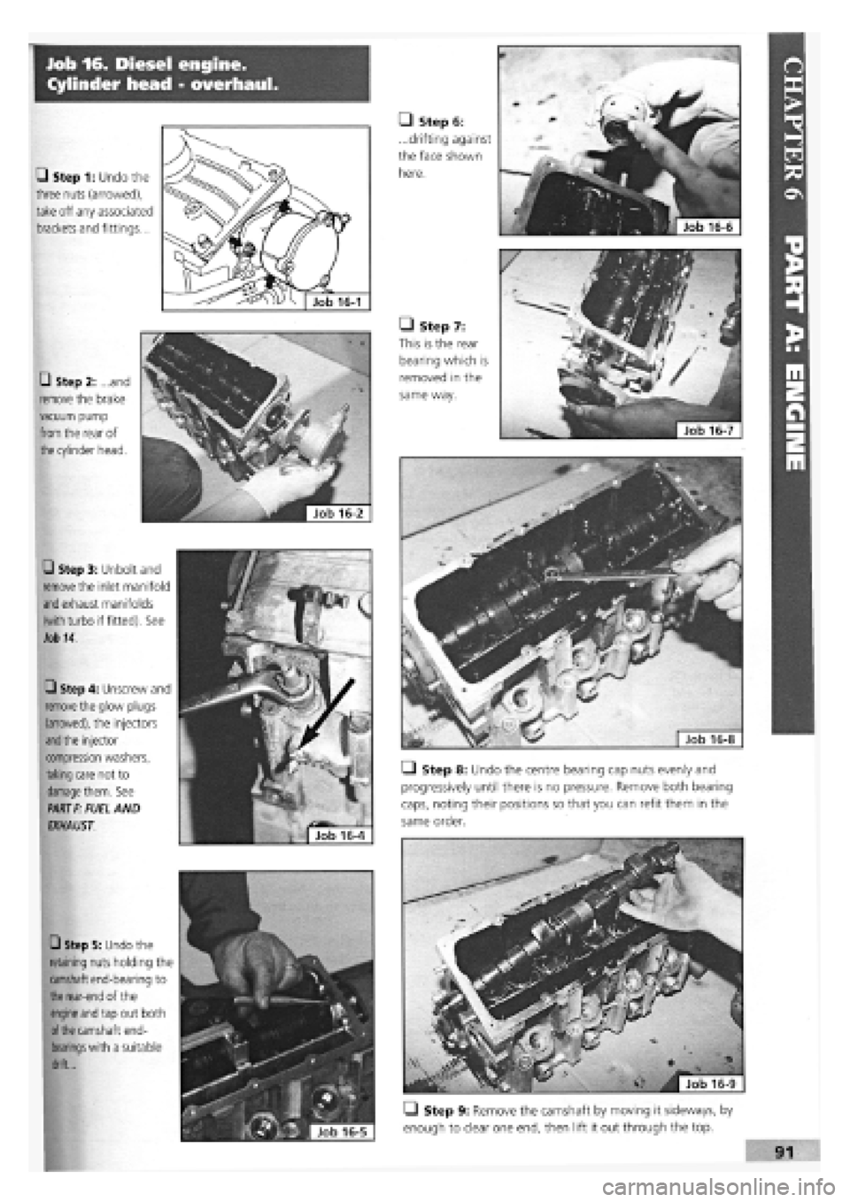
• Step 1: Undo the
three nuts (arrowed),
take off any associated
brackets and fittings...
• Step 2: ...and
remove the brake
vacuum pump
from
the rear of
the
cylinder head.
• Step 3: Unbolt and
remove
the inlet manifold
and
exhaust manifolds
(with
turbo if fitted). See
Job 14.
Q Step 4: Unscrew and
remove
the glow plugs
(arrowed), the injectors
and the
injector
compression washers,
taking
care not to
damage them.
See
PART F:
FUEL AND
EXHAUST.
• Step 5: Undo the
retaining nuts holding the
camshaft end-bearing to
the rear-end
of the
engine and
tap out both
of the
camshaft end-
bearings with
a suitable
drift...
• Step 8: Undo the centre bearing cap nuts evenly and
progressively until there is no pressure. Remove both bearing
caps, noting their positions so that you can refit them in the
same order.
• Step 9: Remove the camshaft by moving it sideways, by
enough to clear one end, then lift it out through the top.
• Step 6:
...drifting against
the face shown
here.
• Step 7:
This is the rear
bearing which is
removed in the
same way.
Page 88 of 171
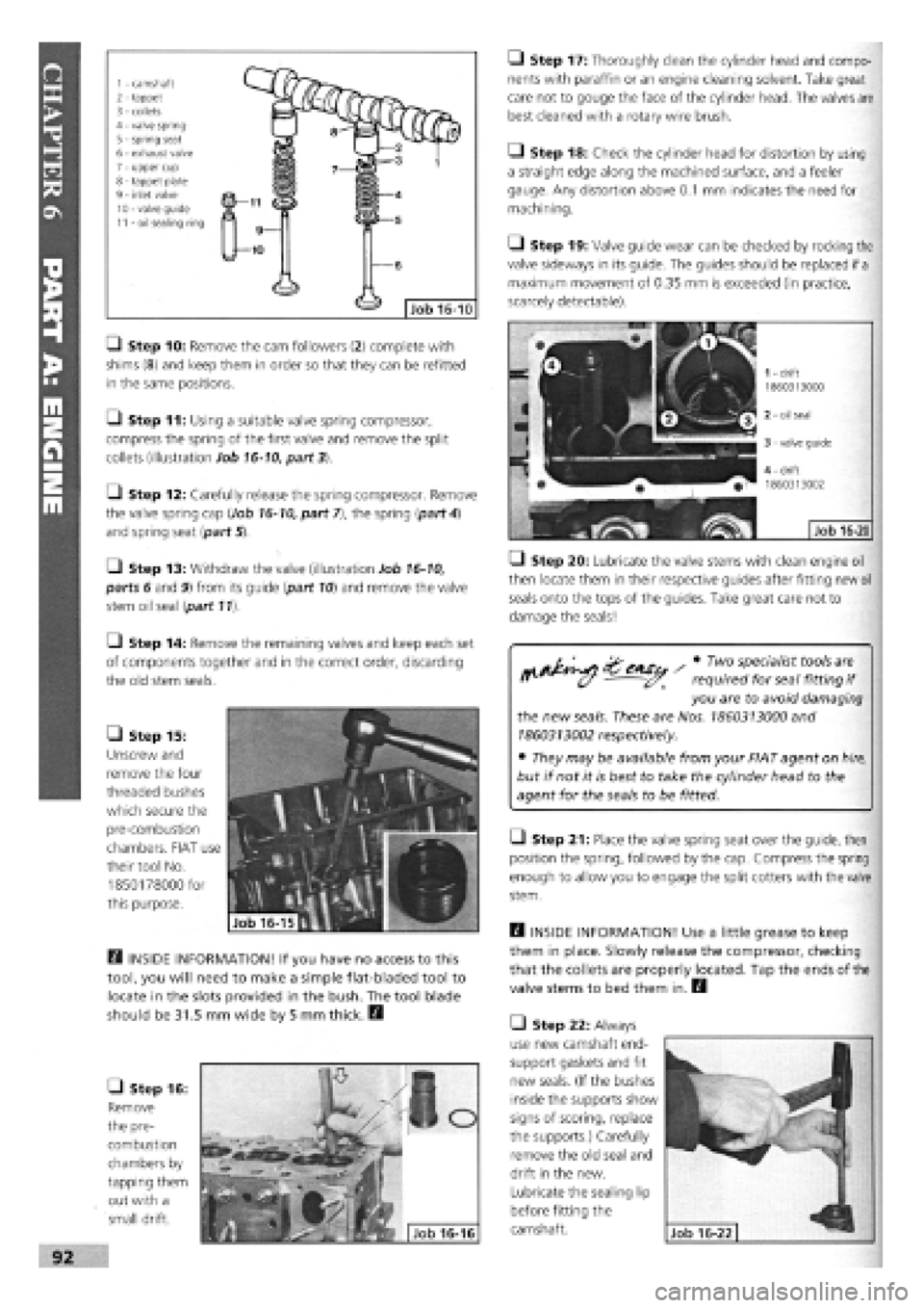
1 - camshaft 2 - tappet 3 - collets 4 - valve spring 5
-
spring seat 6 - exhaust valve 7 - upper cup 8 - tappet plate 9 - inlet valve 10 - valve guide 11 - oil sealing ring
• Step 10: Remove the cam followers (2) complete with
shims
(8)
and keep them in order so that they can be refitted
in the same positions.
O Step 11: Using a suitable valve spring compressor,
compress the spring of the first valve and remove the split
collets (illustration Job
16-10,
part 3).
[J Step 12: Carefully release the spring compressor. Remove
the valve spring cap (Job
16-10,
part 7), the spring {part
4)
and spring seat {part 5).
•
Step 13: Withdraw the valve (illustration Job
16-10,
parts 6 and 9) from its guide {part
10)
and remove the valve
stem oil seal {part 11).
Q Step 14: Remove the remaining valves and keep each set
of components together and in the correct order, discarding
the old stem seals.
• Step 15:
Unscrew and
remove the four
threaded bushes
which secure the
pre-combustion
chambers. FIAT use
their tool No.
1850178000 for
this purpose.
Q INSIDE INFORMATION! If you have no access to this
tool, you will need to make a simple flat-bladed tool to
locate in the slots provided in the bush. The tool blade
should be 31.5 mm wide by 5 mm thick. B
• Step 16:
Remove
the pre-
combustion
chambers by
tapping them
out with a
small drift.
Q Step 17: Thoroughly clean the cylinder head and compo-
nents with paraffin or an engine cleaning solvent. Take great
care not to gouge the face of the cylinder head. The valves are
best cleaned with a rotary wire brush.
• Step 18: Check the cylinder head for distortion by using
a straight edge along the machined surface, and a feeler
gauge. Any distortion above
0.1
mm indicates the need for
machining.
Q Step 19: Valve guide wear can be checked by rocking the
valve sideways in its guide. The guides should be replaced if
a
maximum movement of 0.35 mm is exceeded (in practice,
scarcely detectable).
• Step 20: Lubricate the valve stems with clean engine oil
then locate them in their respective guides after fitting new
oil
seals onto the tops of the guides. Take great care not to
damage the seals!
^ ^^iSu / * TW°
VfaliSt*?0lS
"'I
f' (y - required for seal fitting
if
you are to avoid damaging
the new
seals.
These are Nos.
1860313000
and
1860313002
respectively.
• They may be available from your FIAT agent on
hire,
but if not it is best to take the cylinder head to the
agent for the seals to be fitted.
Q Step 21: Place the valve spring seat over the guide, then
position the spring, followed by the cap. Compress the spring
enough to allow you to engage the split cotters with the valve
stem.
Q INSIDE INFORMATION! Use a little grease to keep
them in place. Slowly release the compressor, checking
that the collets are properly located. Tap the ends of the
valve stems to bed them in. B
• Step 22: Always
use new camshaft end-
support gaskets and fit
new seals. (If the bushes
inside the supports show
signs of scoring, replace
the supports.) Carefully
remove the old seal and
drift in the new.
Lubricate the sealing lip
before fitting the
camshaft.
Page 89 of 171
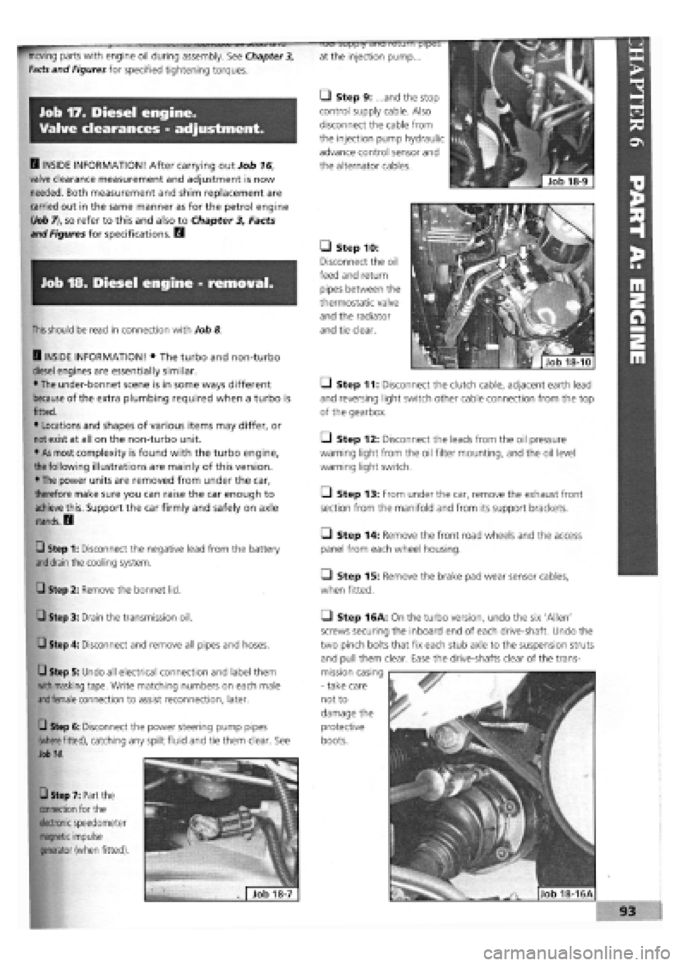
Job 17. Diesel engine.
Valve clearances - adjustment.
D INSIDE INFORMATION! After carrying out Job 16,
valve clearance measurement and adjustment is now
needed. Both measurement and shim replacement are
carried out in the same manner as for the petrol engine
(.Job
7), so refer to this and also to Chapter 3, Facts
and Figures for specifications. B
Job 18. Diesel engine - removal.
moving parts with engine oil during assembly. See Chapter 3,
Facts
and Figures for specified tightening torques.
luei suppiy diiu leium pipe;>
at the injection pump...
• Step 9: ...and the stop
control supply cable. Also
disconnect the cable from
the injection pump hydraulic
advance control sensor and
the alternator cables.
• Step 10:
Disconnect the oil
feed and return
pipes between the
thermostatic valve
and the radiator
and tie clear.
I
This should
be read in connection with Job 8
Q INSIDE INFORMATION! • The turbo and non-turbo
diesel engines are essentially similar.
• The under-bonnet scene is in some ways different
because of the extra plumbing required when a turbo is
fitted.
• Locations and shapes of various items may differ, or
not exist at all on the non-turbo unit.
• As most complexity is found with the turbo engine,
I
the
following illustrations are mainly of this version.
• The power units are removed from under the car,
therefore make sure you can raise the car enough to
achieve this. Support the car firmly and safely on axle
stands. D
Q Step 1: Disconnect the negative lead from the battery
and drain
the cooling system. Q Step 2: Remove the bonnet lid.
• Step 3: Drain the transmission oil.
Q Step 4: Disconnect and remove all pipes and hoses.
Q Step 5: Undo all electrical connection and label them
with masking
tape. Write matching numbers on each male
and female
connection to assist reconnection, later.
Q Step 6: Disconnect the power steering pump pipes
(where fitted),
catching any spilt fluid and tie them clear. See
Job 14.
• Step 7: Part the
connection for the
electronic
speedometer
magnetic impulse
generator
(when fitted).
Q Step 11: Disconnect the clutch cable, adjacent earth lead
and reversing light switch other cable connection from the top
of the gearbox.
• Step 12: Disconnect the leads from the oil pressure
warning light from the oil filter mounting, and the oil level
warning light switch.
• Step 13: From under the car, remove the exhaust front
section from the manifold and from its support brackets.
O Step 14: Remove the front road wheels and the access
panel from each wheel housing.
• Step 15: Remove the brake pad wear sensor cables,
when fitted.
Q Step 16A: On the turbo version, undo the six 'Allen'
screws securing the inboard end of each drive-shaft. Undo the
two pinch bolts that fix each stub axle to the suspension struts
and pull them clear. Ease the drive-shafts clear of the trans-
mission casing
-
take care
not to
damage the
protective
boots.
Page 90 of 171
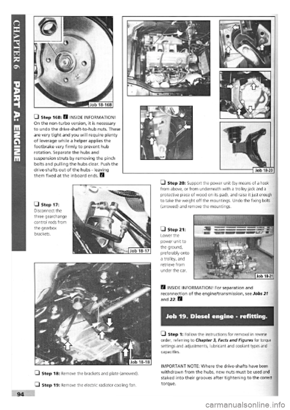
Job 19. Diesel engine - refitting.
• Step 18: Remove the brackets and plate (arrowed).
Q Step 19: Remove the electric radiator cooling fan.
• Step 1: Follow the instructions for removal in reverse
order, referring to Chapter
3,
Facts and Figures for torque
settings and adjustments, lubricant and coolant types and
capacities.
IMPORTANT NOTE: Where the drive-shafts have been
withdrawn from the hubs, new nuts must be used and
staked into their grooves after tightening to the correct
torque.
• Step 16B: D INSIDE INFORMATION!
On the non-turbo version, it is necessary
to undo the drive-shaft-to-hub nuts. These
are very tight and you will require plenty
of leverage while a helper applies the
footbrake very firmly to prevent hub
rotation. Separate the hubs and
suspension struts by removing the pinch
bolts and pulling the hubs clear. Push the
drive-shafts out of the hubs
-
leaving
them fixed at the inboard ends. E3
• Step 17:
Disconnect the
three gearchange
control rods from
the gearbox
brackets.
H INSIDE INFORMATION! For separation and
reconnection of the engine/transmission, see Jobs
21
and 22 Q
• Step 20: Support the power unit (by means of a hook
from above, or from underneath with a trolley jack and a
protective piece of wood on its pad), and raise it just enough
to take the weight off the mountings. Undo the fixing bolts
(arrowed) and remove the mountings.
• Step 21:
Lower the
power unit to
the ground,
preferably onto
a trolley, and
retrieve from
under the car.
Job 18-16B