FORD FESTIVA 1991 Service Manual
Manufacturer: FORD, Model Year: 1991, Model line: FESTIVA, Model: FORD FESTIVA 1991Pages: 454, PDF Size: 9.53 MB
Page 331 of 454
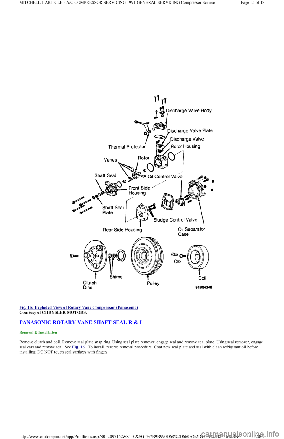
Fig. 15: Exploded View of Rotary Vane Compressor (Panasonic)
Courtesy of CHRYSLER MOTORS.
PANASONIC ROTARY VANE SHAFT SEAL R & I
Removal & Installation
Remove clutch and coil. Remove seal plate snap ring. Using seal plate remover, engage seal and remove seal plate. Using seal remo ve r , e n ga ge
seal ears and remove seal. See Fig. 16
. To install, reverse removal procedure. Coat new seal plate and seal with clean refrigerant oil before
installing. DO NOT touch seal surfaces with fingers.
Page 15 of 18 MITCHELL 1 ARTICLE - A/C COMPRESSOR SERVICING 1991 GENERAL SERVICING Compressor Service
3/10/2009 http://www.eautorepair.net/app/PrintItems.asp?S0=2097152&S1=0&SG=%7B9B990D68%2D660A%2D45E9%2D8F46%2DE
...
Page 332 of 454
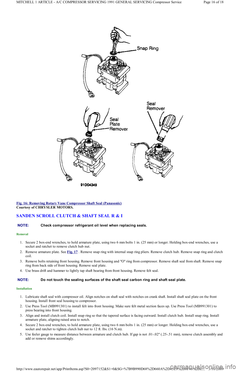
Fig. 16: Removing Rotary Vane Compressor Shaft Seal (Panasonic)
Courtesy of CHRYSLER MOTORS.
SANDEN SCROLL CLUTCH & SHAFT SEAL R & I
Removal
1. Secure 2 box-end wrenches, to hold armature plate, using two 6 mm bolts 1 in. (25 mm) or longer. Holding box-end wrenches, use a
socket and ratchet to remove clutch hub nut.
2. Remove armature plate. See Fig. 17
. Remove snap ring with internal snap ring pliers. Remove clutch hub. Remove snap ring and clutch
coil.
3. Remove bolts retaining front housing. Remove front housing and "O" ring from compressor. Remove shaft seal from shaft. Remove snap
ring from back side of front housing. Remove seal plate.
4. Use brass drift and hammer to lightly tap shaft bearing from front housing. Remove felt seal.
Installation
1. Lubricate shaft seal with compressor oil. Align notches on shaft seal with notches on crank shaft. Install shaft seal plate on the front
housing. Install front seal housing to compressor.
2. Use Press Tool (MB991301) to install felt into front housing. Make sure felt metal section faces up. Use Press Tool (MB991301) to
press bearing into front housing.
3. Align and install clutch coil. Install snap ring so that the tapered surface is facing outward. Install clutch hub. Install snap ring. Install
armature plate, aligning raised area to notch.
4. Secure 2 box-end wrenches, to hold armature plate, using two 6 mm bolts 1 in. (25 mm) or longer. Holding box-end wrenches, use a
socket and ratchet to tighten clutch hub nut to 12 ft. lbs. (16 N.m).
5. Use feeler gauge to measure distance between armature and clutch hub. If gap is not .01-.02" (.25-.51 mm), remove clutch assemb l y an d
add or remove shims accordingly.
NOTE:Check com pressor refrigerant oil level when replacing seals.
NOTE:Do not touch the sealing surfaces of the shaft seal carbon ring and shaft seal plate.
Page 16 of 18 MITCHELL 1 ARTICLE - A/C COMPRESSOR SERVICING 1991 GENERAL SERVICING Compressor Service
3/10/2009 http://www.eautorepair.net/app/PrintItems.asp?S0=2097152&S1=0&SG=%7B9B990D68%2D660A%2D45E9%2D8F46%2DE
...
Page 333 of 454
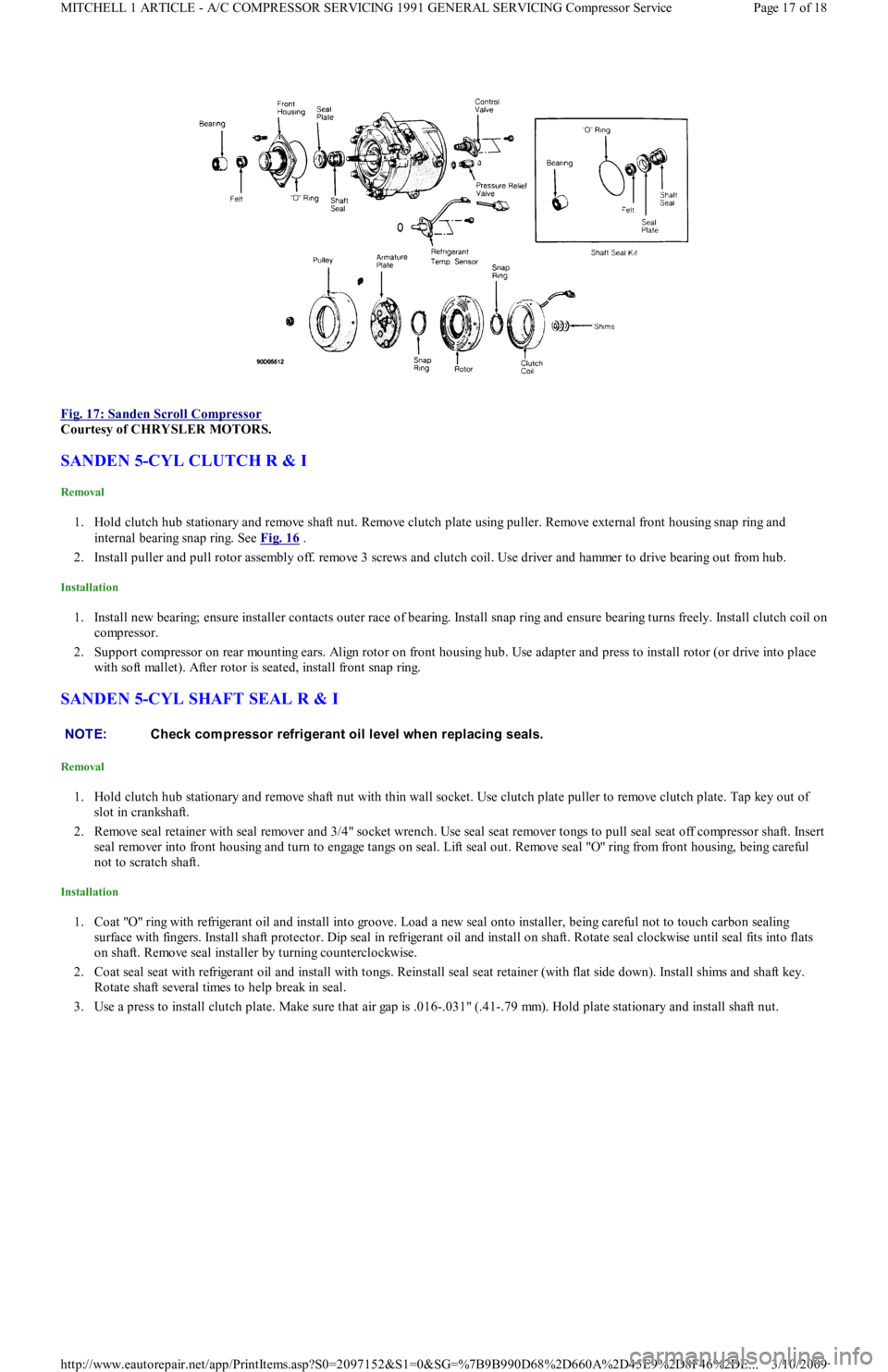
Fig. 17: Sanden Scroll Compressor
Courtesy of CHRYSLER MOTORS.
SANDEN 5-CYL CLUTCH R & I
Removal
1. Hold clutch hub stationary and remove shaft nut. Remove clutch plate using puller. Remove external front housing snap ring and
internal bearing snap ring. See Fig. 16
.
2. Install puller and pull rotor assembly off. remove 3 screws and clutch coil. Use driver and hammer to drive bearing out from hub.
Installation
1. Install new bearing; ensure installer contacts outer race of bearing. Install snap ring and ensure bearing turns freely. Install clutch coil on
compressor.
2. Support compressor on rear mounting ears. Align rotor on front housing hub. Use adapter and press to install rotor (or drive into place
with soft mallet). After rotor is seated, install front snap ring.
SANDEN 5-CYL SHAFT SEAL R & I
Removal
1. Hold clutch hub stationary and remove shaft nut with thin wall socket. Use clutch plate puller to remove clutch plate. Tap key out of
slot in crankshaft.
2. Remove seal retainer with seal remover and 3/4" socket wrench. Use seal seat remover tongs to pull seal seat off compressor shaft. Insert
seal remover into front housing and turn to engage tangs on seal. Lift seal out. Remove seal "O" ring from front housing, being careful
not to scratch shaft.
Installation
1. Coat "O" ring with refrigerant oil and install into groove. Load a new seal onto installer, being careful not to touch carbon sealing
surface with fingers. Install shaft protector. Dip seal in refrigerant oil and install on shaft. Rotate seal clockwise until seal fits into flats
on shaft. Remove seal installer by turning counterclockwise.
2. Coat seal seat with refrigerant oil and install with tongs. Reinstall seal seat retainer (with flat side down). Install shims and shaft key.
Rotate shaft several times to help break in seal.
3. Use a press to install clutch plate. Make sure that air gap is .016-.031" (.41-.79 mm). Hold plate stationary and install shaft n u t .
NOTE:Check com pressor refrigerant oil level when replacing seals.
Page 17 of 18 MITCHELL 1 ARTICLE - A/C COMPRESSOR SERVICING 1991 GENERAL SERVICING Compressor Service
3/10/2009 http://www.eautorepair.net/app/PrintItems.asp?S0=2097152&S1=0&SG=%7B9B990D68%2D660A%2D45E9%2D8F46%2DE
...
Page 334 of 454
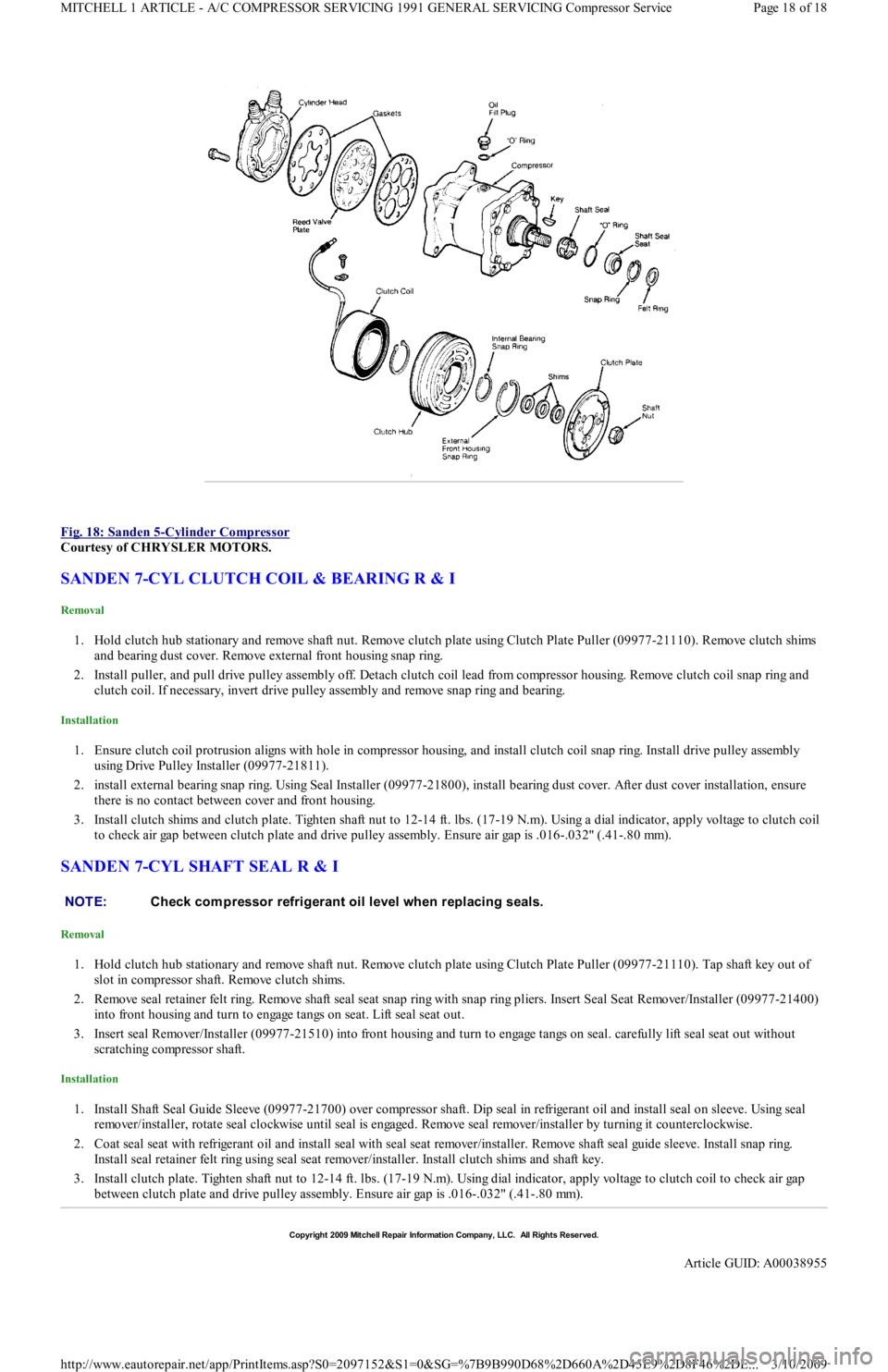
Fig. 18: Sanden 5
-Cylinder Compressor
Courtesy of CHRYSLER MOTORS.
SANDEN 7-CYL CLUTCH COIL & BEARING R & I
Removal
1. Hold clutch hub stationary and remove shaft nut. Remove clutch plate using Clutch Plate Puller (09977-21110). Remove clutch shims
and bearing dust cover. Remove external front housing snap ring.
2. Install puller, and pull drive pulley assembly off. Detach clutch coil lead from compressor housing. Remove clutch coil snap ring and
clutch coil. If necessary, invert drive pulley assembly and remove snap ring and bearing.
Installation
1. Ensure clutch coil protrusion aligns with hole in compressor housing, and install clutch coil snap ring. Install drive pulley assembly
using Drive Pulley Installer (09977-21811).
2. install external bearing snap ring. Using Seal Installer (09977-21800), install bearing dust cover. After dust cover installation, ensure
there is no contact between cover and front housing.
3. Install clutch shims and clutch plate. Tighten shaft nut to 12-14 ft. lbs. (17-19 N.m). Using a dial indicator, apply voltage to clutch coil
to check air gap between clutch plate and drive pulley assembly. Ensure air gap is .016-.032" (.41-.80 mm).
SANDEN 7-CYL SHAFT SEAL R & I
Removal
1. Hold clutch hub stationary and remove shaft nut. Remove clutch plate using Clutch Plate Puller (09977-21110). Tap shaft key out of
slot in compressor shaft. Remove clutch shims.
2. Remove seal retainer felt ring. Remove shaft seal seat snap ring with snap ring pliers. Insert Seal Seat Remover/Installer (09977-21400)
into front housing and turn to engage tangs on seat. Lift seal seat out.
3. Insert seal Remover/Installer (09977-21510) into front housing and turn to engage tangs on seal. carefully lift seal seat out without
scratching compressor shaft.
Installation
1. Install Shaft Seal Guide Sleeve (09977-21700) over compressor shaft. Dip seal in refrigerant oil and install seal on sleeve. Using seal
remover/installer, rotate seal clockwise until seal is engaged. Remove seal remover/installer by turning it counterclockwise.
2. Coat seal seat with refrigerant oil and install seal with seal seat remover/installer. Remove shaft seal guide sleeve. Install snap ring.
Install seal retainer felt ring using seal seat remover/installer. Install clutch shims and shaft key.
3. Install clutch plate. Tighten shaft nut to 12-14 ft. lbs. (17-19 N.m). Using dial indicator, apply voltage to clutch coil to check air gap
between clutch plate and drive pulley assembly. Ensure air gap is .016-.032" (.41-.80 mm).
NOTE:Check com pressor refrigerant oil level when replacing seals.
Copyr ight 2009 Mitchell Repair Information Company, LLC. All Rights Reserved.
Article GUID: A00038955
Page 18 of 18 MITCHELL 1 ARTICLE - A/C COMPRESSOR SERVICING 1991 GENERAL SERVICING Compressor Service
3/10/2009 http://www.eautorepair.net/app/PrintItems.asp?S0=2097152&S1=0&SG=%7B9B990D68%2D660A%2D45E9%2D8F46%2DE
...
Page 335 of 454
Back To Article
1991-92 AIR CONDIT IONING & HEAT ING
A/C System General Servicing
HANDLING/SAFETY PRECAUTIONS
1. Always work in a well-ventilated, clean area. Refrigerant R-134a is colorless and is invisible as a gas. Refrigerant (R-12 or R-134a) is
heavier than oxygen and will displace oxygen in a confined area. Avoid breathing refrigerant vapors. Exposure may irritate eyes, nose
and throat.
2. The system's high pressure can cause severe injury to eyes and skin if a hose were to burst. Always wear eye protection when working
around A/C system and refrigerant. If necessary, wear rubber gloves or other protective clothing.
3. Refrigerant evaporates quickly when exposed to atmosphere, freezing anything it contacts. If liquid refrigerant contacts eyes or skin, DO
NOT rub eyes or skin. Immediately flush affected area with cool water for 15 minutes and consult a doctor or hospital.
4. Never use R-134a in combination with compressed air for leak testing. Pressurized R-134a in the presence of oxygen (air concentrations
greater than 60% by volume) may form a combustible mixture. DO NOT introduce compressed air into R-134a containers (full or
empty), A/C system components or service equipment.
5. DO NOT expose A/C system components to high temperatures, steam cleaning for example, as excessive heat will cause
refrigerant/system pressure to increase. Never expose refrigerant directly to open flame. If refrigerant needs to be warmed, place bottom
of refrigerant tank in warm water. Water temperature MUST NOT exceed 125°F (52°C).
6. Use care when handling refrigerant containers. DO NOT drop, strike, puncture or incinerate containers. Use Department Of
Transportation (DOT) approved, DOT 4BW or DOT 4BA, refrigerant containers.
7. Never overfill refrigerant containers. The safe filling level of a refrigerant container MUST NOT exceed 60% of the container's gross
weight rating. Store refrigerant containers at temperature less than 125°F (52°C).
8. R-12 refrigerant (Freon) will be sold and stored in White containers, while R-134a refrigerant will be sold and stored in 30- or 50-
pound Light Blue containers.
9. R-12 and R-134a refrigerants must never be mixed, as their desiccants and lubricants are not compatible. If the refrigerants are mixed,
system cross-contamination or A/C system component failure may occur. Always use separate servicing and refrigerant
recovery/recycling equipment.
10. Follow equipment manufacturer instructions of all service equipment to be used. The Material Safety Data Sheet (MSDS), provided by
refrigerant manufacturer/suppliers, contains valuable information regarding the safe handling of R-12 or R-134a refrigerants.
IDENTIFYING R-134A SYSTEMS & COMPONENTS
To prevent refrigerant cross-contamination, use following methods to identify R-134a based systems and components.
Fittings & "O" Rings
All R-134a based A/C systems use 1/2" - 16 ACME threaded fittings (identifiable by square threads) and quick-connect service couplings. See
Fig. 1
. Besides the use of these fittings, most manufacturers will use Green colored "O" rings in R-134a systems. CAUT ION: When discharging air conditioning system , use only approved refrigerant recovery/recycling
equipm ent. Make every attem pt to avoid discharging refrigerant into the atm osphere.
Page 1 of 6 MITCHELL 1 ARTICLE - 1991-92 AIR CONDITIONING & HEATING A/C System General Servicing
3/10/2009 http://www.eautorepair.net/app/PrintItems.asp?S0=2097152&S1=0&SG=%7B9B990D68%2D660A%2D45E9%2D8F46%2DE
...
Page 336 of 454
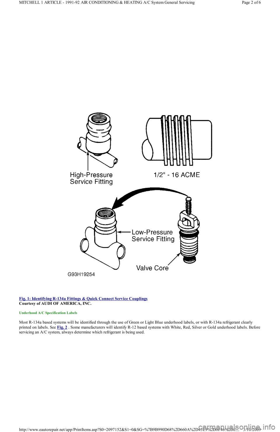
Fig. 1: Identifying R
-134a Fittings & Quick Connect Service Couplings
Courtesy of AUDI OF AMERICA, INC.
Underhood A/C Specification Labels
Most R-134a based systems will be identified through the use of Green or Light Blue underhood labels, or with R-134a refrigerant clearly
printed on labels. See Fig. 2 . Some manufacturers will identify R-12 based systems with White, Red, Silver or Gold underhood labels. Before
servicing an A/C system, always determine which refrigerant is being used.
Page 2 of 6 MITCHELL 1 ARTICLE - 1991-92 AIR CONDITIONING & HEATING A/C System General Servicing
3/10/2009 http://www.eautorepair.net/app/PrintItems.asp?S0=2097152&S1=0&SG=%7B9B990D68%2D660A%2D45E9%2D8F46%2DE
...
Page 337 of 454
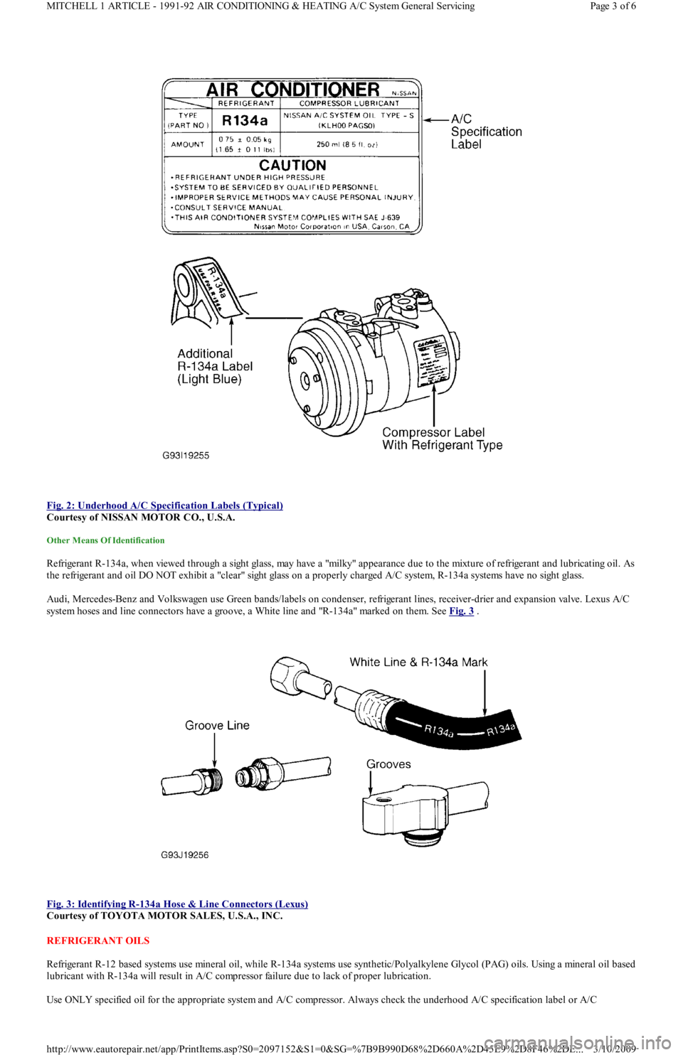
Fig. 2: Underhood A/C Specification Labels (Typical)
Courtesy of NISSAN MOTOR CO., U.S.A.
Other Means Of Identification
Refrigerant R-134a, when viewed through a sight glass, may have a "milky" appearance due to the mixture of refrigerant and lubricating oil. As
the refrigerant and oil DO NOT exhibit a "clear" sight glass on a properly charged A/C system, R-134a systems have no sight glass.
Audi, Mercedes-Benz and Volkswagen use Green bands/labels on condenser, refrigerant lines, receiver-drier and expansion valve. Lexus A/C
system hoses and line connectors have a groove, a White line and "R-134a" marked on them. See Fig. 3
.
Fig. 3: Identifying R
-134a Hose & Line Connectors (Lexus)
Courtesy of TOYOTA MOTOR SALES, U.S.A., INC.
REFRIGERANT OILS
Refrigerant R-12 based systems use mineral oil, while R-134a systems use synthetic/Polyalkylene Glycol (PAG) oils. Using a mineral oil based
lubricant with R-134a will result in A/C compressor failure due to lack of proper lubrication.
Use ONLY specified oil for the appropriate system and A/C compressor. Always check the underhood A/C specification label or A/C
Page 3 of 6 MITCHELL 1 ARTICLE - 1991-92 AIR CONDITIONING & HEATING A/C System General Servicing
3/10/2009 http://www.eautorepair.net/app/PrintItems.asp?S0=2097152&S1=0&SG=%7B9B990D68%2D660A%2D45E9%2D8F46%2DE
...
Page 338 of 454
compressor label before adding refrigerant oil to A/C compressor/system. See Fig. 2 . The following R-134a refrigerant oils are currently
available.
Lexus
PAG Refrigerant Oil (ND-OIL 8) with 10P/10PA swashplate (piston) compressor. Synthetic Refrigerant Oil (ND-OIL 9) with through-va n e
(rotary vane) compressor.
Mercedes-Benz
PAG Refrigerant Oil (001 989 08 03).
Nissan
PAG Refrigerant Oil (KLH00-PAGR0) with rotary vane compressor. PAG Refrigerant Oil (KLH00-PAGS0) with piston (swashplate)
compressor.
Saab
PAG Refrigerant Oil (40 74 787).
SERVICE EQUIPMENT
Because R-134a is not interchangeable with R-12, separate sets of hoses, manifold gauge set and recovery/recycling equipment are required to
service vehicles. This is necessary to avoid cross-contaminating and damaging system.
All equipment used to service systems using R-134a must meet SAE standard J1991. The service hoses on the manifold gauge set must have
manual (turn wheel) or automatic back-flow valves at the service port connector ends. This will prevent refrigerant from being released into
the atmosphere.
For identification purposes, R-134a service hoses must have a Black stripe along its length and be clearly labeled SAE J2196/R-134a. The low
pressure test hose is Blue with a Black stripe. The high pressure test hose is Red with a Black stripe, and the center test hose is Yellow with a
Black stripe.
R-134a manifold gauge sets can be identified by one or all of the following.
Labeled FOR USE WITH R-134a on set
Labeled HFC-134 or R-134a on gauge face
Light Blue color on gauge face
In addition, pressure/temperature scales on R-134a gauge sets are different from R-12 manifold gauge sets.
SYSTEM SERVICE VALVES
SCHRADER-TYPE VALVES
Schrader valve is similar in construction and operation to a tire valve. When a test gauge hose with built-in valve core depressor is attached,
Schrader stem is pushed inward to the open position and allows system pressure to reach gauge.
If test hose does not have a built-in core depressor, an adapter must be used. Never attach hose or adapter to Schrader valve unless it is first
connected to manifold gauge set.
Refrigerant R-12 Schrader-type valve cores have TV5 thread size. Refrigerant R-134a Schrader-type valve cores use M6 (Metric) threads. R-
134a valve cores can be easily identified by use of "O" rings and external spring. See Fig. 1
.
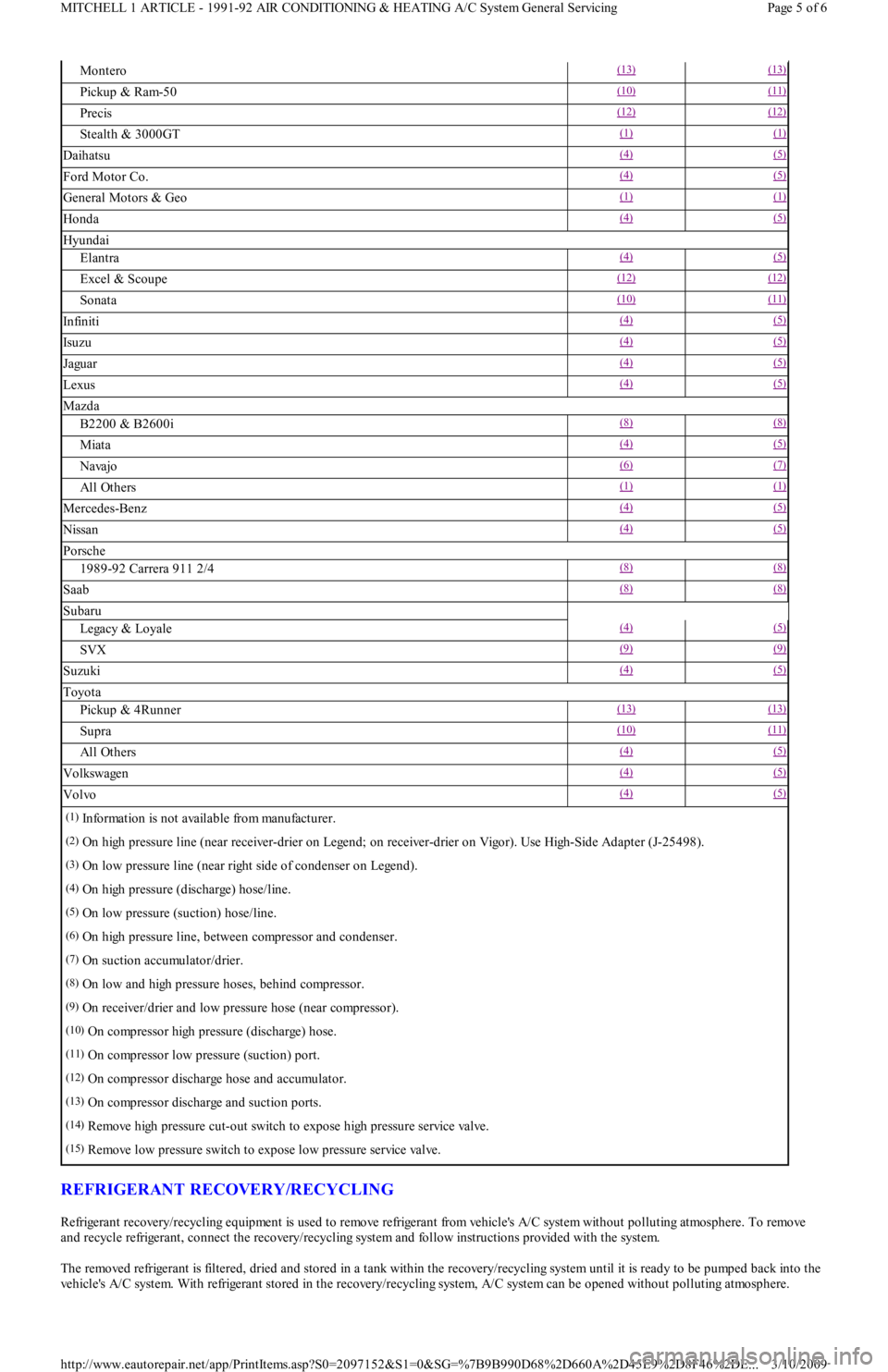
SERVICE VALVE LOCATIONS
SERVICE VALVE LOCATIONS NOTE:Synthetic/PAG oils absorb m oisture very rapidly, 2.3-5.6% by weight, as com pared to a m ineral oil
absorption rate of .005% by weight.
NOTE:Refrigerant R-12 service hoses will ONLY be labeled SAE J2196.
NOTE:Although sim ilar in construction and operation to a tire valve, NEVER replace a Schrader-type valve
with a tire valve.
VehicleHighLow
Audi(14) (15)
Acura(2) (3)
BMW(4) (5)
Chrysler, Eagle & Mitsubishi
Colt, Mirage & Summit(10) (11)
Colt Vista & Summit Wagon(10) (11)
Diamante(1) (1)
Eclipse & Expo(10) (11)
Galant(10) (11)
Page 4 of 6 MITCHELL 1 ARTICLE - 1991-92 AIR CONDITIONING & HEATING A/C System General Servicing
3/10/2009 http://www.eautorepair.net/app/PrintItems.asp?S0=2097152&S1=0&SG=%7B9B990D68%2D660A%2D45E9%2D8F46%2DE
...
Page 339 of 454
REFRIGERANT RECOVERY/RECYCLING
Refrigerant recovery/recycling equipment is used to remove refrigerant from vehicle's A/C system without polluting atmosphere. To remove
and recycle refrigerant, connect the recovery/recycling system and follow instructions provided with the system.
The removed refrigerant is filtered, dried and stored in a tank within the recovery/recycling system until it is ready to be pumped back into the
vehicle's A/C system. With refrigerant stored in the recovery/recycling system, A/C system can be opened without polluting atmosphere.
Montero(13) (13)
Pickup & Ram-50(10) (11)
Precis(12) (12)
Stealth & 3000GT(1) (1)
Daihatsu(4) (5)
Ford Motor Co.(4) (5)
General Motors & Geo(1) (1)
Honda(4) (5)
Hyundai
Elantra(4) (5)
Excel & Scoupe(12) (12)
Sonata(10) (11)
In fin it i(4) (5)
Isu zu(4) (5)
Jaguar(4) (5)
Lexus(4) (5)
Mazda
B2200 & B2600i(8) (8)
Miata(4) (5)
Navajo(6) (7)
All Others(1) (1)
Mercedes-Benz(4) (5)
Nissan(4) (5)
Porsche
1989-92 Carrera 911 2/4(8) (8)
Saab(8) (8)
Subaru
Legacy & Loyale(4) (5)
SVX(9) (9)
Suzuki(4) (5)
Toyota
Pickup & 4Runner(13) (13)
Supra(10) (11)
All Others(4) (5)
Volkswagen(4) (5)
Volvo(4) (5)
(1)Information is not available from manufacturer.
(2)On high pressure line (near receiver-drier on Legend; on receiver-drier on Vigor). Use High-Side Adapter (J-25498).
(3)On low pressure line (near right side of condenser on Legend).
(4)On high pressure (discharge) hose/line.
(5)On low pressure (suction) hose/line.
(6)On high pressure line, between compressor and condenser.
(7)On suction accumulator/drier.
(8)On low and high pressure hoses, behind compressor.
(9)On receiver/drier and low pressure hose (near compressor).
(10)On compressor high pressure (discharge) hose.
(11)On compressor low pressure (suction) port.
(12)On compressor discharge hose and accumulator.
(13)On compressor discharge and suction ports.
(14)Remove high pressure cut-out switch to expose high pressure service valve.
(15)Remove low pressure switch to expose low pressure service valve.
Page 5 of 6 MITCHELL 1 ARTICLE - 1991-92 AIR CONDITIONING & HEATING A/C System General Servicing
3/10/2009 http://www.eautorepair.net/app/PrintItems.asp?S0=2097152&S1=0&SG=%7B9B990D68%2D660A%2D45E9%2D8F46%2DE
...
Page 340 of 454
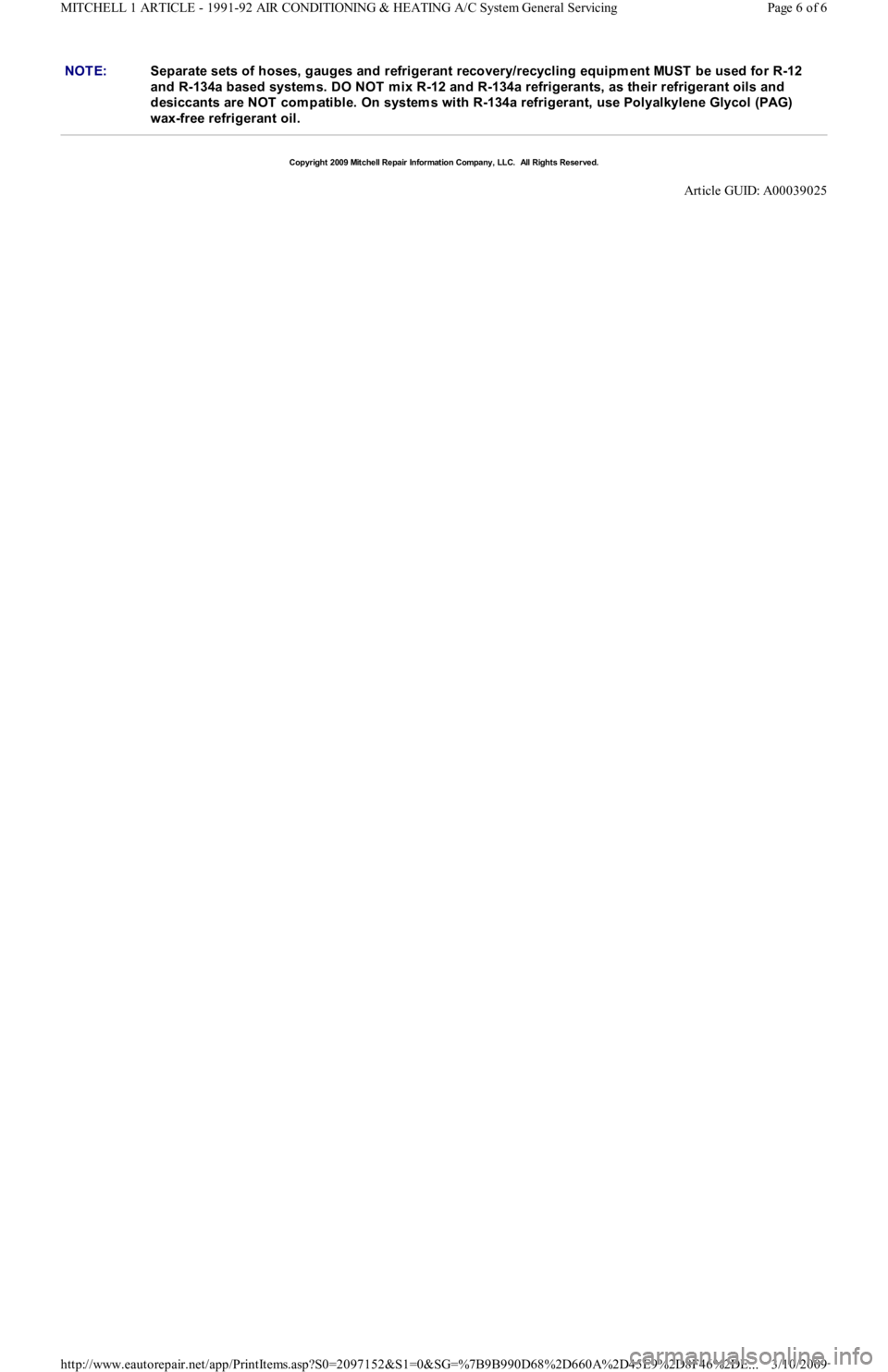
NOTE:Separate sets of hoses, gauges and refrigerant recovery/recycling equipm ent MUST be used for R-12
and R-134a based system s. DO NOT m ix R-12 and R-134a refrigerants, as their refrigerant oils and
desiccants are NOT com patible. On system s with R-134a refrigerant, use Polyalkylene Glycol (PAG)
wax-free refrigerant oil.
Copyr ight 2009 Mitchell Repair Information Company, LLC. All Rights Reserved.
Article GUID: A00039025
Page 6 of 6 MITCHELL 1 ARTICLE - 1991-92 AIR CONDITIONING & HEATING A/C System General Servicing
3/10/2009 http://www.eautorepair.net/app/PrintItems.asp?S0=2097152&S1=0&SG=%7B9B990D68%2D660A%2D45E9%2D8F46%2DE
...