FORD FESTIVA 1991 Service Manual
Manufacturer: FORD, Model Year: 1991, Model line: FESTIVA, Model: FORD FESTIVA 1991Pages: 454, PDF Size: 9.53 MB
Page 341 of 454
Back To Article
A/C SYST EM PRECAUT IONS
A/C GENERAL SERVICING A/C System Servicing cautions
BEFORE OPENING THE SYSTEM
Before disconnecting any lines or fittings, the system must be completely discharged using approved refrigerant recovery/recycling equipment.
DISCHARGING A/C SYSTEM
1. Remove service valve caps and install gauges. For high side gauge hose, Adapter (D81L-19703-A) must be used to connect to high side
service valve.
2. Place open end of center hose in garage exhaust outlet or in a well ventilated area. Slightly open low side gauge valve and let refrigerant
escape slowly without loosing refrigerant oil.
3. When system is nearly discharged, using approved refrigerant recovery/recycling equipment, open high side gauge valve to release any
pressure trapped in compressor. Close valves immediately after discharging to prevent entry of moisture.
DISCONNECTING LINES & FITTINGS
1. After system is discharged, using approved refrigerant recovery/recycling equipment, carefully clean entire area around coupling nut to
prevent dirt entering system. Always use two wrenches to avoid twisting or distorting lines and fittings (hold fitting with one wrench
while loosening coupling nut with second wrench).
2. Ford spring-coupling fittings require a special coupling tool (Motorcraft YT-1056) to open or close. See procedure under Connecting
Lines and Fittings.
3. Cap or plug all LINES and FITTINGS immediately to prevent entry of air and moisture into system. Do not remove these caps until
connections are being made.
COMPONENT REPLACEMENT
When components are replaced, system oil level must be adjusted. Add refrigeration oil to replacement component. See Compressor oil Check
article, as well as COMPONENT OIL REPLACEMENT QUANTITIES chart under A/C SYSTEM SPECS article in this section.
USING R-12 REFRIGERANT - SAFETY PRECAUTIONS
1. Always work in a well-ventilated, clean area. Refrigerant (R-12) is heavier than oxygen, and will displace oxygen in a confined area.
Always wear eye protection when working around air conditioning systems and R-12. The system's high pressure can cause severe injury
to eyes and skin if a hose were to burst. R-12 evaporates quickly when exposed to atmosphere, freezing anything it contacts.
2. Use care when handling refrigerant containers. DO NOT drop or strike containers or expose refrigerant containers to excessive heat.
Containers must never be heated more than 125°F (52°C). Never expose R-12 directly to open flame.
USING INDIVIDUAL R-12 CANS
Disposable refrigerant cans (referred to as one pound cans) have a flat type seal or a screw type seal, and proper can tap must be used for each
type. Be sure sealing gasket on can tap is in good condition. A proper safety can tap will prevent refrigerant from flowing back into open can,
as tap has a one-way flow control.
MULTI-CAN DISPENSING VALVES
A multi-can dispensing valve allows attachment of several cans of refrigerant, and is a good substitute when a bulk container is not available.
Cans are installed onto each leg of multi-can dispensing valve in the same manner as the individual cans, and each leg has its own can tap.
CAN TAP INSTALLATION FLAT TYPE SEAL CANS
On cam-lock or one-piece can taps, first turn the handle outward to the fully open position. Securely engage locking lugs over the can flange,
and lock them in place by turning cam lock or locking nut. Screw tap assembly into adapter so sealing gasket is fully seated against the can
top. Turn tap inward to pierce the can and close the tap. DO NOT open tap until ready to purge the service hose or dispense refrigerant into
the system.
On 2-piece can taps, be certain tap handle is turned fully inward to the closed position. Check that locking base is turned to its outer limit.
Securely engage locking lugs over the can flange. Turn entire tap assembly (without disturbing the closed setting) downward into the locking
base to pierce the can. DO NOT open tap until ready to dispense into system. CAUT ION: When discharging air conditioning system , use only approved refrigerant recovery/recycling
equipm ent. Make every attem pt to avoid discharging refrigerant into the atm osphere.
NOTE:Recent findings by the EPA indicate that R-11, R-12 and R-113 are harm ful to the Earths' protective
Ozone layer. Make every attem pt possible, to avoid discharging R-11, R-12 or R-113 into the
atm osphere.
CAUT ION: When R-12 is exposed to an open flam e, drawn into a running engine, or detected with a Halide
(propane) leak tester, poisonous phosgene gas is form ed. Keep work areas ventilated and avoid
running engines near work area.
NOTE:Recent findings by the EPA indicate that refrigerant is harm ful to the Earth's protective Ozone layer.
When discharging refrigerant avoid allowing refrigerant to enter the atm osphere. Refrigerant recovery
system should be used when discharging the system .
Page 1 of 2 MITCHELL 1 ARTICLE - A/C SYSTEM PRECAUTIONS A/C GENERAL SERVICING A/C System Servicing cautions
3/10/2009 http://www.eautorepair.net/app/PrintItems.asp?S0=2097152&S1=0&SG=%7B9B990D68%2D660A%2D45E9%2D8F46%2DE
...
Page 342 of 454
SCREW TYPE SEAL CANS
Ensure can tap is fully closed. Screw refrigerant can into can tap fitting until tight. This will pierce the can. Connect tap to center hose on
manifold gauge set. DO NOT open tap until ready to dispense R-12 into system.
CONNECTING LINES & FITTINGS
1. A new "O" ring should be used in all instances when connecting lines and fittings (dip "O" ring in clean refrigeration oil and make
certain it is not twisted during installation). Always use two wrenches to avoid twisting or distorting lines and fittings, tighten coupling
nuts securely.
2. Ford spring-coupling fittings require a special coupling tool (Motorcraft YT-1056) to open or close. Use the following procedure to
connect or disconnect the spring-coupling fitting.
Ford Spring-Coupling Fitting
1. Discharge system using approved refrigerant recovery/recycling equipment. Place proper end of tool over refrigerant line. Tool fits both
3/8" and 1/2" fittings. Push tool into fitting cage to release spring inside. Pull lines apart and remove tool.
2. Before connecting, check internal spring for damage. If necessary, pry spring out and replace it. Clean fittings and install new "O" rings.
Fig. 1: Assembling Ford Spring
-Coupling Fitting
PLACING SYSTEM IN OPERATION
After component replacement and/or system servicing has been completed and all connections have been made, proceed as follows:
1. Evacuate the system using a vacuum pump.
2. Charge the system with new R-12 (refrigerant) according to each individual vehicle as outlined in the GENERAL SERVICING article.
Also see Refrigerant Capacity in this Section.
3. Leak test the system, with particular attention to all new connections and components.
4. Make a performance test of the system. Never assume that a recharging has automatically corrected a problem.
COMPRESSOR REMOVAL INFORMATION - ISOLATION METHOD
On systems which have compressors equipped with stem-type service valves (Tecumseh), it is possible to isolate the compressor for removal.
Isolating
Turn both high and low pressure manual valves to extreme clockwise (front seat) position. Loosen cap on high pressure manual valve
connection to compressor and allow gas to escape until compressor is relieved of pressure.
COMPRESSOR REMOVAL INFORMATION-DISCHARGE METHOD
This procedure is to be used on vehicles which have compressor equipped with Schrader service valves. In these cases, the compressor cannot
be isolated and the system must be discharged, using approved refrigerant recovery/recycling equipment, prior to compressor removal. WARNING:DO NOT open high side hand valve while air conditioning system is in operation. T his high pressure
could rupture can or fitting at safety can valve, resulting in dam age and personal injury.
CAUT ION: Use ONLY "O" rings designed for these Ford fittings (Motorcraft YF-982). Norm al refrigerant "O" rings
will NOT seal.
Copyr ight 2009 Mitchell Repair Information Company, LLC. All Rights Reserved.
Article GUID: A00039191
Page 2 of 2 MITCHELL 1 ARTICLE - A/C SYSTEM PRECAUTIONS A/C GENERAL SERVICING A/C System Servicing cautions
3/10/2009 http://www.eautorepair.net/app/PrintItems.asp?S0=2097152&S1=0&SG=%7B9B990D68%2D660A%2D45E9%2D8F46%2DE
...
Page 343 of 454
Back To Article
1991 GENERAL SERVICING
A/C System Specifications - Applications & Oil/R-12 Capacities
COMPRESSOR APPLICATIONS - PASSENGER CARS
COMPRESSOR APPLICATIONS - PASSENGER CARS
COMPRESSOR APPLICATIONS - LIGHT TRUCKS & VANS
COMPRESSOR APPLICATIONS - LIGHT TRUCKS & VANS
BODY CODE DESIGNATIONS - LIGHT TRUCKS & VANS
BODY CODE DESIGNATIONS - LIGHT TRUCKS & VANS
REFRIGERANT OIL & R-12 CAPACITY - PASSENGER CARS
PASSENGER CAR REFRIGERANT OIL & R-12 CAPACITY
ApplicationCompressor
ContinentalFord FX-15 10-Cyl.
Cougar & ThunderbirdFord FX-15 10-Cyl.
Crown Victoria, Grand Marquis & Town CarFord FX-15 10-Cyl.
Escort & TracerNippondenso 10P13 10-Cyl.
Mark VIINippondenso 10PA17 10-Cyl.
Mustang
2.3L EngineNippondenso 10P15 10-Cyl.
5.0L EngineNippondenso 6P-148 6-Cyl.
Probe
2.2L EngineNippondenso 10P15A 10-Cyl.
3.0L EngineNippondenso 10P15 10-Cyl.
Sable & Taurus
2.5L EngineFord FS-6 6-Cyl.
3.0L & 3.8L EnginesFord FX-15 10-Cyl.
3.0L SHO EngineNippondenso 10P15F 10-Cyl.
Tempo & TopazNippondenso 10P15 10-Cyl.
ApplicationCompressor
AerostarFord FX-15 10-Cyl.
BroncoFord FX-15 10-Cyl.
"E " SeriesFord FS-6 6-Cyl.
ExplorerFord FX-15 10-Cyl.
"F" Series
7.3L DieselFord FS-6 6-Cyl.
Gas Engine ModelsFord FX-15 10-Cyl.
Ranger
2.3L EngineFord FX-15 10-Cyl.
2.9L EngineFord FS-6 6-Cyl.
4.0L EngineFord FX-15 10-Cyl.
ModelDesignation
Aerostar"A" Series
Bronco & Explorer"U" Series
Pickups (Full Size)"F" Series
Ranger"R" Series
Vans (Full Size)"E " Series
Application(1) Oil OuncesR-12 Ounces
Continental8.040
Cougar & Thunderbird7.040
Crown Victoria, Grand Marquis & Town Car7.040-48
Escort & Tracer8.036
Mark VII8.040
Mustang
10P15 Compressor8.040
6P148 Compressor10.040
Probe
10P15 Compressor8.040
10P15A Compressor3.340
Sable & Taurus
FS-6 Compressor10.044
FX-15 Compressor7.044
10P15 Compressor8.040
Page 1 of 2 MITCHELL 1 ARTICLE - 1991 GENERAL SERVICING A/C System Specifications - Applications & Oil/R-12 Capacities
3/10/2009 http://www.eautorepair.net/app/PrintItems.asp?S0=2097152&S1=0&SG=%7B9B990D68%2D660A%2D45E9%2D8F46%2DE
...
Page 344 of 454
REFRIGERANT OIL & R-12 CAPACITY - LIGHT TRUCKS & VANS
LIGHT TRUCK & VAN REFRIGERANT OIL & R-12 CAPACITY
10P15F Compressor8.040
Tempo & Topaz8.036
(1)Total system capacity, unless otherwise noted.
Application(1) Oil OuncesR-12 Ounces
Aerostar (FX-15 Compressor)
W/Auxiliary Unit10.0(2) 56
W/O Auxiliary Unit7.056
Bronco7.052
Explorer10.032
"E " Series
W/Rear Unit10.072
W/O Rear Unit7.060
"F" Series7.052
Ranger
FS-6 Compressor10.032
FX-15 Compressor7.036
(1)Total system capacity, unless otherwise noted.
(2)Models with auxiliary unit may require additional refrigerant. See decal under hood for capacity.
Copyr ight 2009 Mitchell Repair Information Company, LLC. All Rights Reserved.
Article GUID: A00039007
Page 2 of 2 MITCHELL 1 ARTICLE - 1991 GENERAL SERVICING A/C System Specifications - Applications & Oil/R-12 Capacities
3/10/2009 http://www.eautorepair.net/app/PrintItems.asp?S0=2097152&S1=0&SG=%7B9B990D68%2D660A%2D45E9%2D8F46%2DE
...
Page 345 of 454
Back To Article
HEAT ER SYST EM
1990-92 HEAT ER SYST EMS Ford Motor Co.
DESCRIPTION
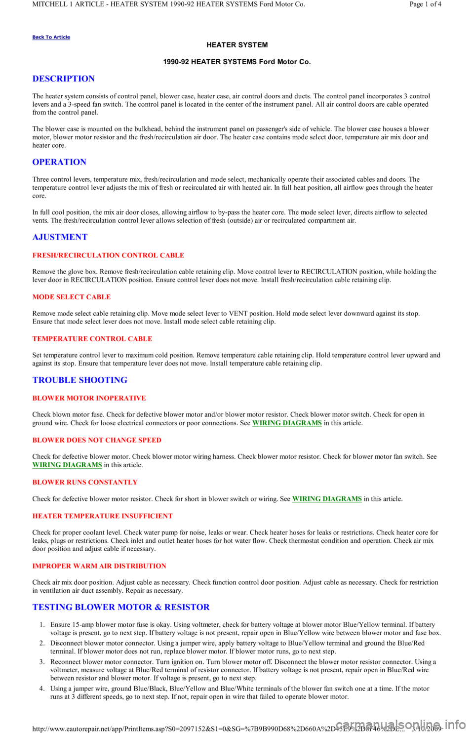
The heater system consists of control panel, blower case, heater case, air control doors and ducts. The control panel incorporates 3 control
levers and a 3-speed fan switch. The control panel is located in the center of the instrument panel. All air control doors are cable operated
from the control panel.
The blower case is mounted on the bulkhead, behind the instrument panel on passenger's side of vehicle. The blower case houses a blower
motor, blower motor resistor and the fresh/recirculation air door. The heater case contains mode select door, temperature air mix door and
heater core.
OPERATION
Three control levers, temperature mix, fresh/recirculation and mode select, mechanically operate their associated cables and doors. The
temperature control lever adjusts the mix of fresh or recirculated air with heated air. In full heat position, all airflow goes through the heater
core.
In full cool position, the mix air door closes, allowing airflow to by-pass the heater core. The mode select lever, directs airflow to selected
vents. The fresh/recirculation control lever allows selection of fresh (outside) air or recirculated compartment air.
AJUSTMENT
FRESH/RECIRCULATION CONTROL CABLE
Remove the glove box. Remove fresh/recirculation cable retaining clip. Move control lever to RECIRCULATION position, while holding the
lever door in RECIRCULATION position. Ensure control lever does not move. Install fresh/recirculation cable retaining clip.
MODE SELECT CABLE
Remove mode select cable retaining clip. Move mode select lever to VENT position. Hold mode select lever downward against its stop.
Ensure that mode select lever does not move. Install mode select cable retaining clip.
TEMPERATURE CONTROL CABLE
Set temperature control lever to maximum cold position. Remove temperature cable retaining clip. Hold temperature control lever upward and
against its stop. Ensure that temperature lever does not move. Install temperature cable retaining clip.
TROUBLE SHOOTING
BLOWER MOTOR INOPERATIVE
Check blown motor fuse. Check for defective blower motor and/or blower motor resistor. Check blower motor switch. Check for open in
ground wire. Check for loose electrical connectors or poor connections. See WIRING DIAGRAMS
in this article.
BLOWER DOES NOT CHANGE SPEED
Check for defective blower motor. Check blower motor wiring harness. Check blower motor resistor. Check for blower motor fan switch. See
WIRING DIAGRAMS
in this article.
BLOWER RUNS CONSTANTLY
Check for defective blower motor resistor. Check for short in blower switch or wiring. See WIRING DIAGRAMS
in this article.
HEATER TEMPERATURE INSUFFICIENT
Check for proper coolant level. Check water pump for noise, leaks or wear. Check heater hoses for leaks or restrictions. Check heater core for
leaks, plugs or restrictions. Check inlet and outlet heater hoses for hot water flow. Check thermostat condition and operation. Check air mix
door position and adjust cable if necessary.
IMPROPER WARM AIR DISTRIBUTION
Check air mix door position. Adjust cable as necessary. Check function control door position. Adjust cable as necessary. Check for restriction
in ventilation air duct assembly. Repair as necessary.
TESTING BLOWER MOTOR & RESISTOR
1. Ensure 15-amp blower motor fuse is okay. Using voltmeter, check for battery voltage at blower motor Blue/Yellow terminal. If battery
voltage is present, go to next step. If battery voltage is not present, repair open in Blue/Yellow wire between blower motor and fuse box.
2. Disconnect blower motor connector. Using a jumper wire, apply battery voltage to Blue/Yellow terminal and ground the Blue/Red
terminal. If blower motor does not run, replace blower motor. If blower motor runs, go to next step.
3. Reconnect blower motor connector. Turn ignition on. Turn blower motor off. Disconnect the blower motor resistor connector. Using a
voltmeter, measure voltage at Blue/Red terminal of resistor connector. If battery voltage is not present, repair open in Blue/Red wire
between resistor and blower motor. If voltage is present, go to next step.
4. Using a jumper wire, ground Blue/Black, Blue/Yellow and Blue/White terminals of the blower fan switch one at a time. If the motor
runs at 3 different speeds, go to next step. If not, repair open in wire that failed to operate blower motor.
Page 1 of 4 MITCHELL 1 ARTICLE - HEATER SYSTEM 1990-92 HEATER SYSTEMS Ford Motor Co.
3/10/2009 http://www.eautorepair.net/app/PrintItems.asp?S0=2097152&S1=0&SG=%7B9B990D68%2D660A%2D45E9%2D8F46%2DE
...
Page 346 of 454
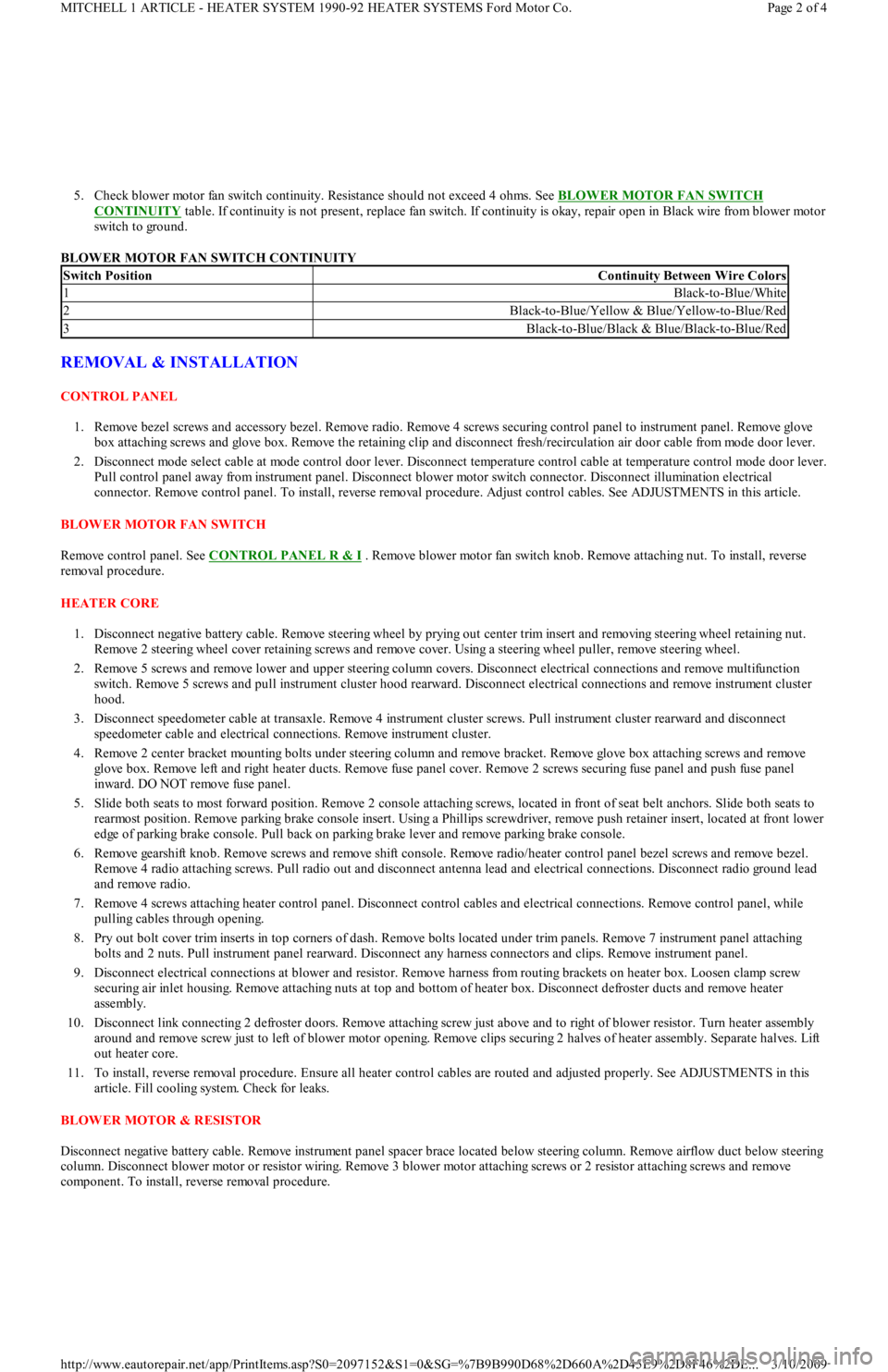
5. Check blower motor fan switch continuity. Resistance should not exceed 4 ohms. See BLOWER MOTOR FAN SWITCH
CONTINUITY table. If continuity is not present, replace fan switch. If continuity is okay, repair open in Black wire from blower motor
switch to ground.
BLOWER MOTOR FAN SWITCH CONTINUITY
REMOVAL & INSTALLATION
CONTROL PANEL
1. Remove bezel screws and accessory bezel. Remove radio. Remove 4 screws securing control panel to instrument panel. Remove glove
box attaching screws and glove box. Remove the retaining clip and disconnect fresh/recirculation air door cable from mode door lever.
2. Disconnect mode select cable at mode control door lever. Disconnect temperature control cable at temperature control mode door lever.
Pull control panel away from instrument panel. Disconnect blower motor switch connector. Disconnect illumination electrical
connector. Remove control panel. To install, reverse removal procedure. Adjust control cables. See ADJUSTMENTS in this article.
BLOWER MOTOR FAN SWITCH
Remove control panel. See CONTROL PANEL R & I
. Remove blower motor fan switch knob. Remove attaching nut. To install, reverse
removal procedure.
HEATER CORE
1. Disconnect negative battery cable. Remove steering wheel by prying out center trim insert and removing steering wheel retaining nut.
Remove 2 steering wheel cover retaining screws and remove cover. Using a steering wheel puller, remove steering wheel.
2. Remove 5 screws and remove lower and upper steering column covers. Disconnect electrical connections and remove multifunction
switch. Remove 5 screws and pull instrument cluster hood rearward. Disconnect electrical connections and remove instrument cluster
hood.
3. Disconnect speedometer cable at transaxle. Remove 4 instrument cluster screws. Pull instrument cluster rearward and disconnect
speedometer cable and electrical connections. Remove instrument cluster.
4. Remove 2 center bracket mounting bolts under steering column and remove bracket. Remove glove box attaching screws and remove
glove box. Remove left and right heater ducts. Remove fuse panel cover. Remove 2 screws securing fuse panel and push fuse panel
inward. DO NOT remove fuse panel.
5. Slide both seats to most forward position. Remove 2 console attaching screws, located in front of seat belt anchors. Slide both seats to
rearmost position. Remove parking brake console insert. Using a Phillips screwdriver, remove push retainer insert, located at front lower
edge of parking brake console. Pull back on parking brake lever and remove parking brake console.
6. Remove gearshift knob. Remove screws and remove shift console. Remove radio/heater control panel bezel screws and remove bezel.
Remove 4 radio attaching screws. Pull radio out and disconnect antenna lead and electrical connections. Disconnect radio ground lead
and remove radio.
7. Remove 4 screws attaching heater control panel. Disconnect control cables and electrical connections. Remove control panel, while
pulling cables through opening.
8. Pry out bolt cover trim inserts in top corners of dash. Remove bolts located under trim panels. Remove 7 instrument panel attaching
bolts and 2 nuts. Pull instrument panel rearward. Disconnect any harness connectors and clips. Remove instrument panel.
9. Disconnect electrical connections at blower and resistor. Remove harness from routing brackets on heater box. Loosen clamp screw
securing air inlet housing. Remove attaching nuts at top and bottom of heater box. Disconnect defroster ducts and remove heater
assembly.
10. Disconnect link connecting 2 defroster doors. Remove attaching screw just above and to right of blower resistor. Turn heater assembly
around and remove screw just to left of blower motor opening. Remove clips securing 2 halves of heater assembly. Separate halves. Lift
out heater core.
11. To install, reverse removal procedure. Ensure all heater control cables are routed and adjusted properly. See ADJUSTMENTS in this
article. Fill cooling system. Check for leaks.
BLOWER MOTOR & RESISTOR
Disconnect negative battery cable. Remove instrument panel spacer brace located below steering column. Remove airflow duct below steering
column. Disconnect blower motor or resistor wiring. Remove 3 blower motor attaching screws or 2 resistor attaching screws and remove
component. To install, reverse removal procedure.
Switch PositionContinuity Between Wire Colors
1Black-to-Blue/White
2Black-to-Blue/Yellow & Blue/Yellow-to-Blue/Red
3Black-to-Blue/Black & Blue/Black-to-Blue/Red
Page 2 of 4 MITCHELL 1 ARTICLE - HEATER SYSTEM 1990-92 HEATER SYSTEMS Ford Motor Co.
3/10/2009 http://www.eautorepair.net/app/PrintItems.asp?S0=2097152&S1=0&SG=%7B9B990D68%2D660A%2D45E9%2D8F46%2DE
...
Page 347 of 454
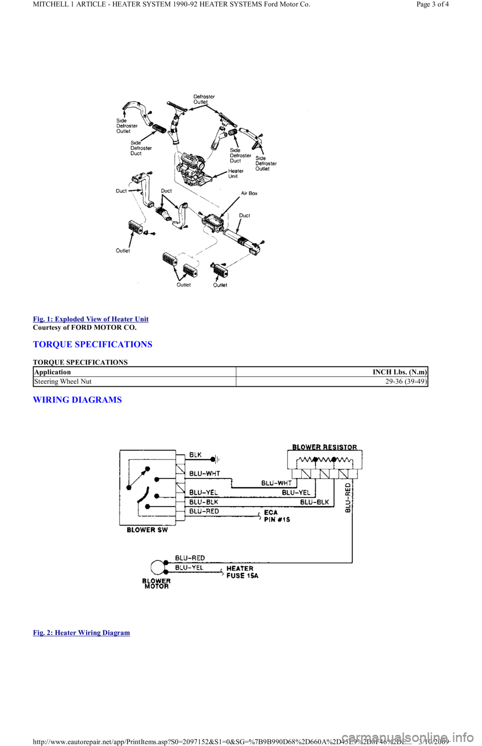
Fig. 1: Exploded View of Heater Unit
Courtesy of FORD MOTOR CO.
TORQUE SPECIFICATIONS
TORQUE SPECIFICATIONS
WIRING DIAGRAMS
Fig. 2: Heater Wiring Diagram
ApplicationINCH Lbs. (N.m)
Steering Wheel Nut29-36 (39-49)
Page 3 of 4 MITCHELL 1 ARTICLE - HEATER SYSTEM 1990-92 HEATER SYSTEMS Ford Motor Co.
3/10/2009 http://www.eautorepair.net/app/PrintItems.asp?S0=2097152&S1=0&SG=%7B9B990D68%2D660A%2D45E9%2D8F46%2DE
...
Page 348 of 454
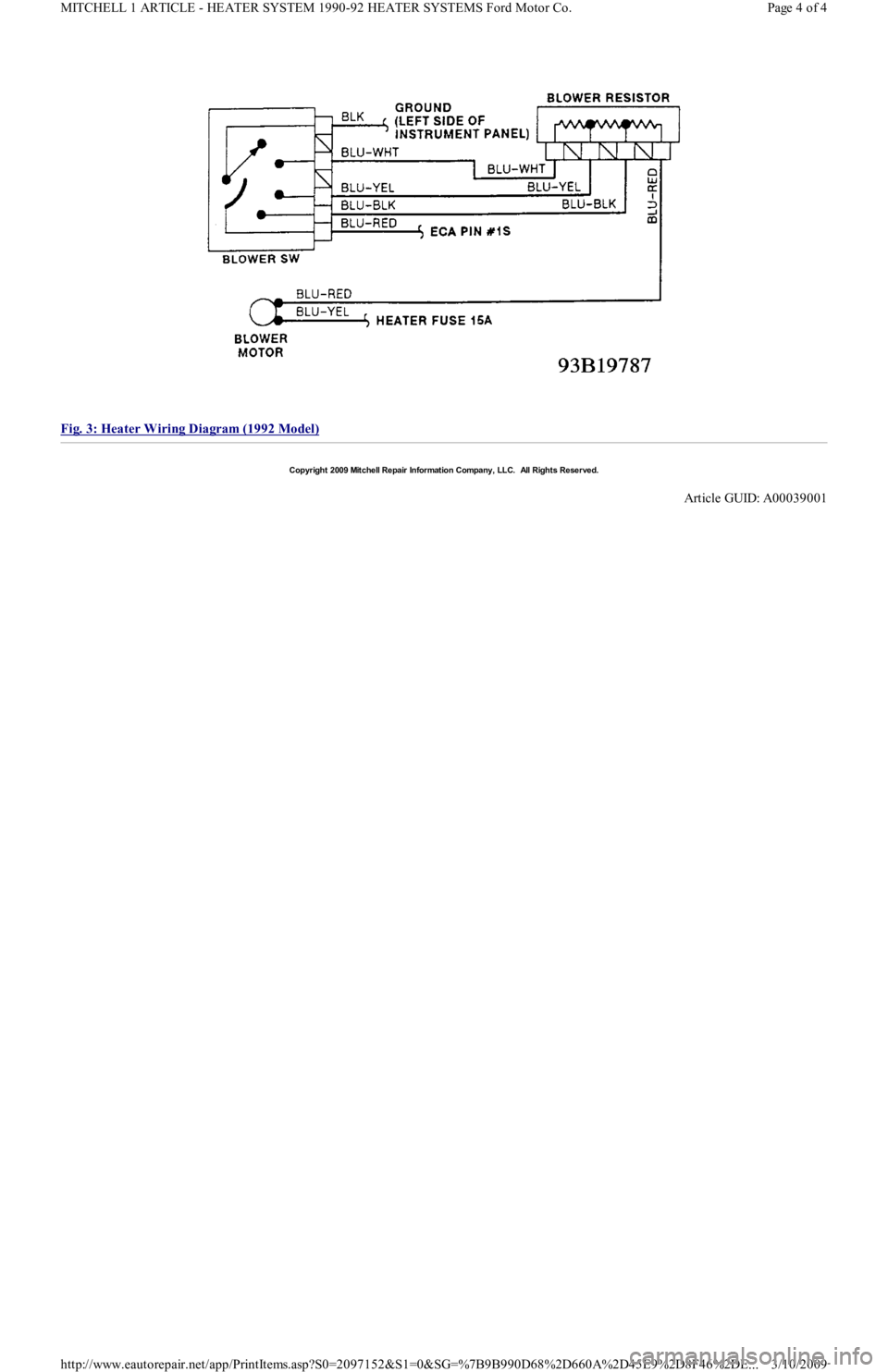
Fig. 3: Heater Wiring Diagram (1992 Model)
Copyr ight 2009 Mitchell Repair Information Company, LLC. All Rights Reserved.
Article GUID: A00039001
Page 4 of 4 MITCHELL 1 ARTICLE - HEATER SYSTEM 1990-92 HEATER SYSTEMS Ford Motor Co.
3/10/2009 http://www.eautorepair.net/app/PrintItems.asp?S0=2097152&S1=0&SG=%7B9B990D68%2D660A%2D45E9%2D8F46%2DE
...
Page 349 of 454
Back To Article
1991 AIR CONDIT IONING & HEAT
MANUAL A/C
A/C SYSTEM SPECIFICATIONS
SPECIFICATIONS
DESCRIPTION
This A/C-heater system is fully integrated to provide cooling, heating and ventilation with either fresh or recirculated air. A/C system is
expansion valve type. Interior air temperature is controlled by cycling the compressor on and off at different rates. A/C compressor is protected
by a low pressure switch, which stops compressor operation when refrigerant pressure is too low. Compressor operation is cut when throttle is
wide open to improve driveability.
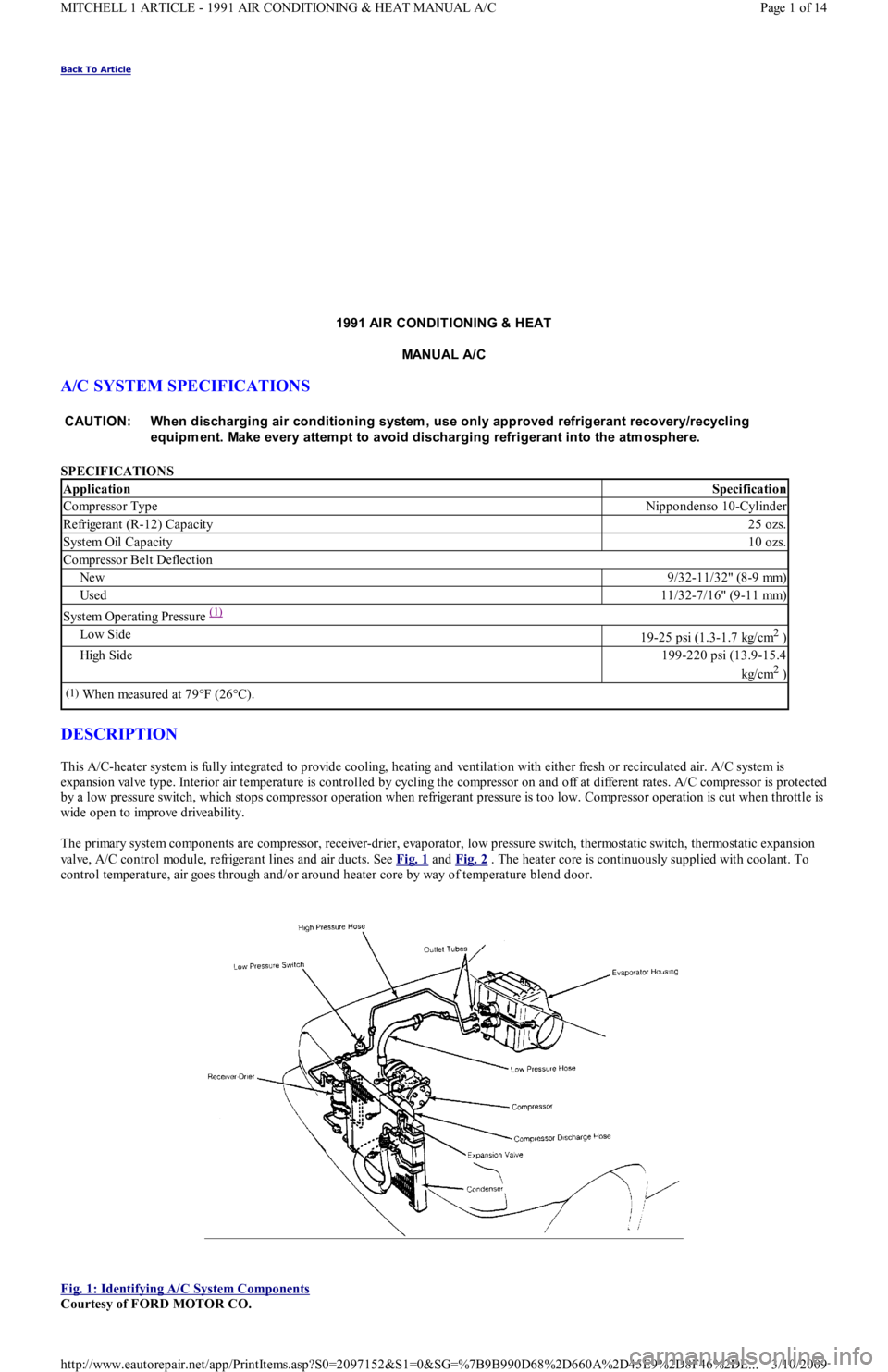
The primary system components are compressor, receiver-drier, evaporator, low pressure switch, thermostatic switch, thermostatic expansion
valve, A/C control module, refrigerant lines and air ducts. See Fig. 1
and Fig. 2 . The heater core is continuously supplied with coolant. To
control temperature, air goes through and/or around heater core by way of temperature blend door.
Fig. 1: Identifying A/C System Components
Courtesy of FORD MOTOR CO. CAUT ION: When discharging air conditioning system , use only approved refrigerant recovery/recycling
equipm ent. Make every attem pt to avoid discharging refrigerant into the atm osphere.
ApplicationSpecification
Compressor TypeNippondenso 10-Cylinder
Refrigerant (R-12) Capacity25 ozs.
System Oil Capacity10 ozs.
Compressor Belt Deflection
New9/32-11/32" (8-9 mm)
Used11/32-7/16" (9-11 mm)
System Operating Pressure (1)
Low Side19-25 psi (1.3-1.7 kg/cm2 )
High Side199-220 psi (13.9-15.4
kg/cm
2 )
(1)When measured at 79°F (26°C).
Page 1 of 14 MITCHELL 1 ARTICLE - 1991 AIR CONDITIONING & HEAT MANUAL A/C
3/10/2009 http://www.eautorepair.net/app/PrintItems.asp?S0=2097152&S1=0&SG=%7B9B990D68%2D660A%2D45E9%2D8F46%2DE
...
Page 350 of 454
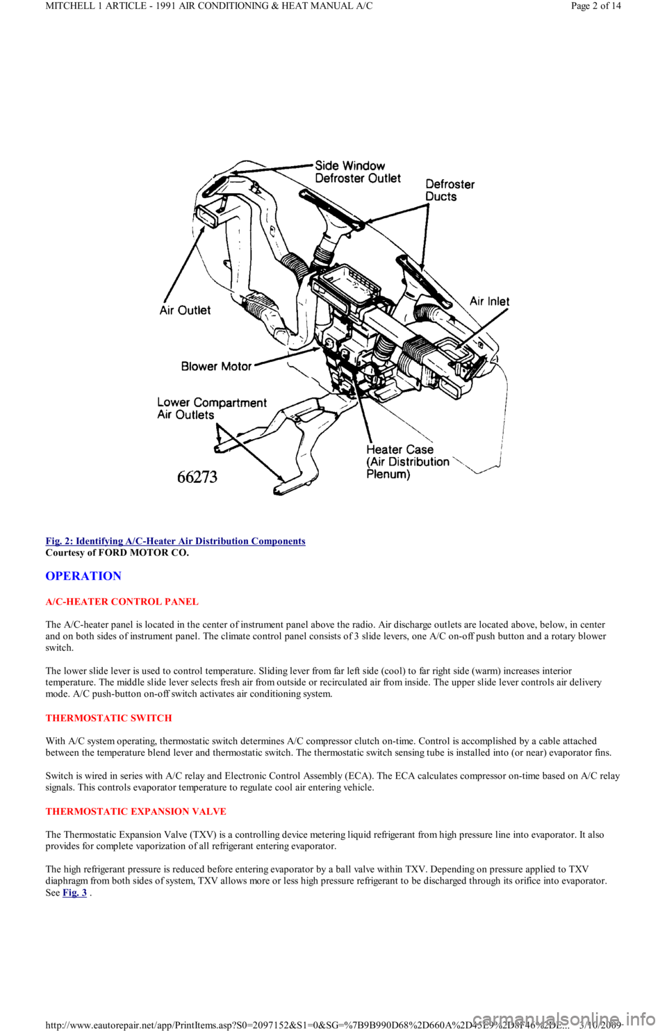
Fig. 2: Identifying A/C
-Heater Air Distribution Components
Courtesy of FORD MOTOR CO.
OPERATION
A/C-HEATER CONTROL PANEL
The A/C-heater panel is located in the center of instrument panel above the radio. Air discharge outlets are located above, below, in center
and on both sides of instrument panel. The climate control panel consists of 3 slide levers, one A/C on-off push button and a rotary blower
switch.
The lower slide lever is used to control temperature. Sliding lever from far left side (cool) to far right side (warm) increases interior
temperature. The middle slide lever selects fresh air from outside or recirculated air from inside. The upper slide lever controls air delivery
mode. A/C push-button on-off switch activates air conditioning system.
THERMOSTATIC SW ITCH
With A/C system operating, thermostatic switch determines A/C compressor clutch on-time. Control is accomplished by a cable attached
between the temperature blend lever and thermostatic switch. The thermostatic switch sensing tube is installed into (or near) evaporator fins.
Switch is wired in series with A/C relay and Electronic Control Assembly (ECA). The ECA calculates compressor on-time based on A/C relay
signals. This controls evaporator temperature to regulate cool air entering vehicle.
THERMOSTATIC EXPANSION VALVE
The Thermostatic Expansion Valve (TXV) is a controlling device metering liquid refrigerant from high pressure line into evaporator. It also
provides for complete vaporization of all refrigerant entering evaporator.
The high refrigerant pressure is reduced before entering evaporator by a ball valve within TXV. Depending on pressure applied to TXV
diaphragm from both sides of system, TXV allows more or less high pressure refrigerant to be discharged through its orifice into evaporator.
See Fig. 3
.
Page 2 of 14 MITCHELL 1 ARTICLE - 1991 AIR CONDITIONING & HEAT MANUAL A/C
3/10/2009 http://www.eautorepair.net/app/PrintItems.asp?S0=2097152&S1=0&SG=%7B9B990D68%2D660A%2D45E9%2D8F46%2DE
...