FORD FESTIVA 1991 Service Manual
Manufacturer: FORD, Model Year: 1991, Model line: FESTIVA, Model: FORD FESTIVA 1991Pages: 454, PDF Size: 9.53 MB
Page 301 of 454
Back To Article
GENERAL INFORMATION
Wheel Alignm ent T heory & Operation
* PLEASE READ THIS FIRST *
PRE-ALIGNMENT INSTRUCTIONS
GENERAL ALIGNMENT CHECKS
Before adjusting wheel alignment, check the following:
Each axle uses tires of same construction and tread style, equal in tread wear and overall diameter. Verify that radial and axial runout is
not excessive. Inflation should be at manufacturer's specifications.
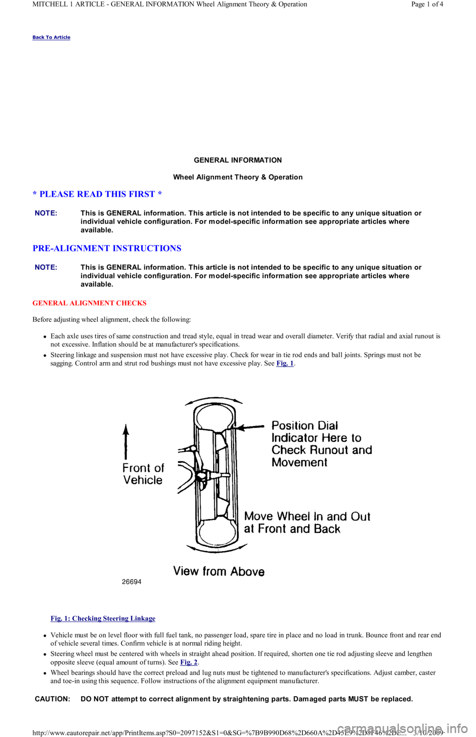
Steering linkage and suspension must not have excessive play. Check for wear in tie rod ends and ball joints. Springs must not be
sagging. Control arm and strut rod bushings must not have excessive play. See Fig. 1
.
Fig. 1: Checking Steering Linkage
Vehicle must be on level floor with full fuel tank, no passenger load, spare tire in place and no load in trunk. Bounce front and rear end
of vehicle several times. Confirm vehicle is at normal riding height.
Steering wheel must be centered with wheels in straight ahead position. If required, shorten one tie rod adjusting sleeve and lengthen
opposite sleeve (equal amount of turns). See Fig. 2
.
Wheel bearings should have the correct preload and lug nuts must be tightened to manufacturer's specifications. Adjust camber, caster
and toe-in using this sequence. Follow instructions of the alignment equipment manufacturer. NOTE:This is GENERAL inform ation. This article is not intended to be specific to any unique situation or
individual vehicle configuration. For m odel-specific inform ation see appropriate articles where
available.
NOTE:This is GENERAL inform ation. This article is not intended to be specific to any unique situation or
individual vehicle configuration. For m odel-specific inform ation see appropriate articles where
available.
CAUT ION: DO NOT attem pt to correct alignm ent by straightening parts. Dam aged parts MUST be replaced.
Page 1 of 4 MITCHELL 1 ARTICLE - GENERAL INFORMATION Wheel Alignment Theory & Operation
3/10/2009 http://www.eautorepair.net/app/PrintItems.asp?S0=2097152&S1=0&SG=%7B9B990D68%2D660A%2D45E9%2D8F46%2DE
...
Page 302 of 454
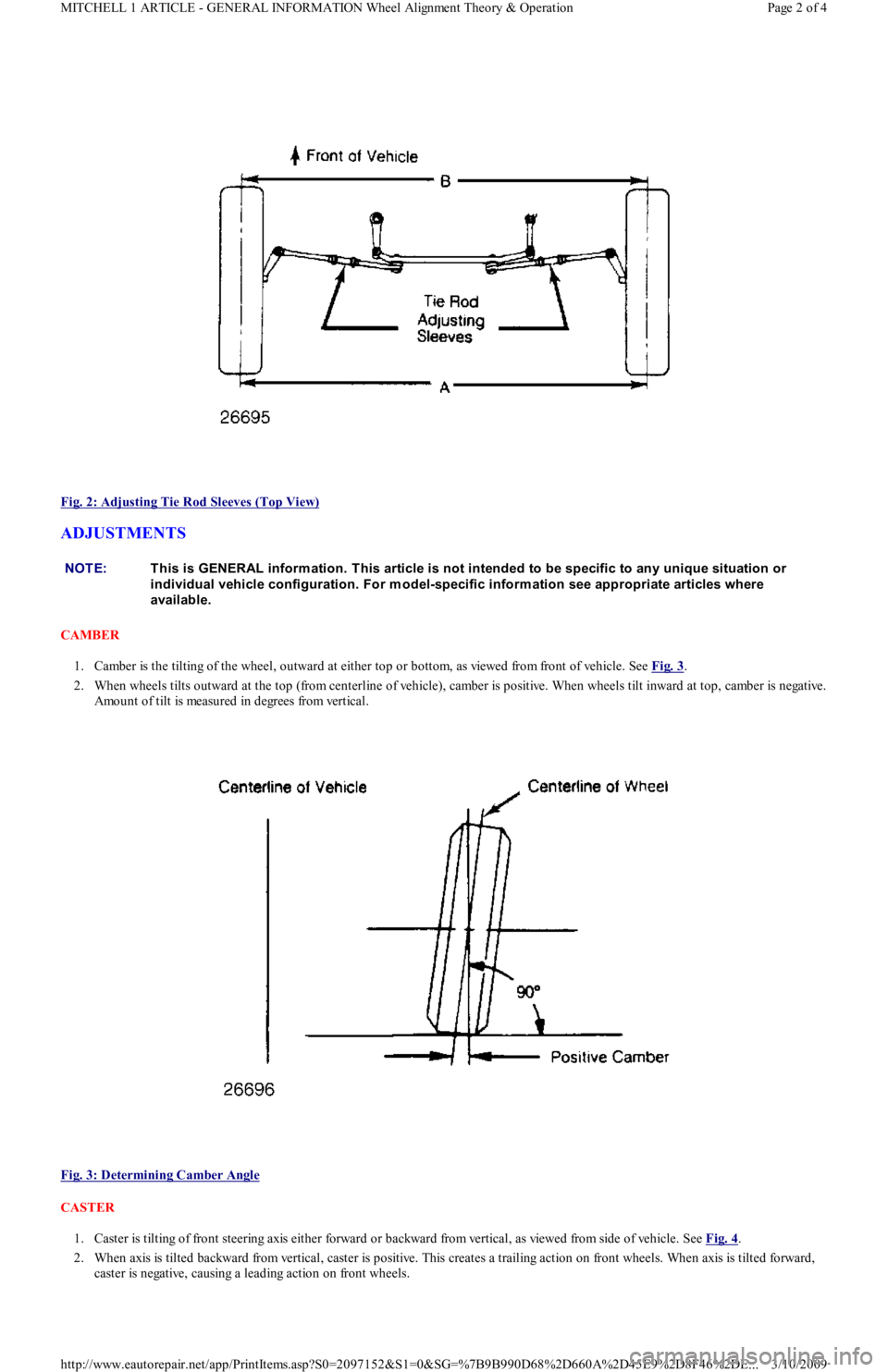
Fig. 2: Adjusting Tie Rod Sleeves (Top View)
ADJUSTMENTS
CAMBER
1. Camber is the tilting of the wheel, outward at either top or bottom, as viewed from front of vehicle. See Fig. 3
.
2. When wheels tilts outward at the top (from centerline of vehicle), camber is positive. When wheels tilt inward at top, camber is negative.
Amount of tilt is measured in degrees from vertical.
Fig. 3: Determining Camber Angle
CASTER
1. Caster is tilting of front steering axis either forward or backward from vertical, as viewed from side of vehicle. See Fig. 4
.
2. When axis is tilted backward from vertical, caster is positive. This creates a trailing action on front wheels. When axis is tilted forward,
caster is negative, causing a leading action on front wheels.
NOTE:This is GENERAL inform ation. This article is not intended to be specific to any unique situation or
individual vehicle configuration. For m odel-specific inform ation see appropriate articles where
available.
Page 2 of 4 MITCHELL 1 ARTICLE - GENERAL INFORMATION Wheel Alignment Theory & Operation
3/10/2009 http://www.eautorepair.net/app/PrintItems.asp?S0=2097152&S1=0&SG=%7B9B990D68%2D660A%2D45E9%2D8F46%2DE
...
Page 303 of 454
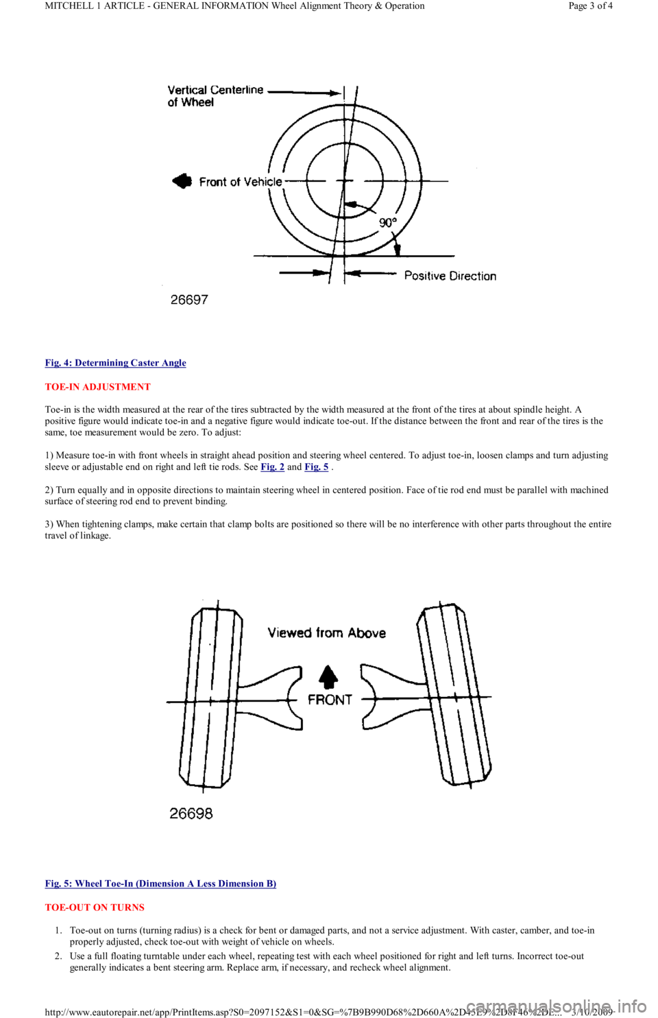
Fig. 4: Determining Caster Angle
TOE-IN ADJUSTMENT
Toe-in is the width measured at the rear of the tires subtracted by the width measured at the front of the tires at about spindle height. A
positive figure would indicate toe-in and a negative figure would indicate toe-out. If the distance between the front and rear of the tires is the
same, toe measurement would be zero. To adjust:
1) Measure toe-in with front wheels in straight ahead position and steering wheel centered. To adjust toe-in, loosen clamps and turn adjusting
sleeve or adjustable end on right and left tie rods. See Fig. 2
and Fig. 5 .
2) Turn equally and in opposite directions to maintain steering wheel in centered position. Face of tie rod end must be parallel with machined
surface of steering rod end to prevent binding.
3) When tightening clamps, make certain that clamp bolts are positioned so there will be no interference with other parts throughout the entire
travel of linkage.
Fig. 5: Wheel Toe
-In (Dimension A Less Dimension B)
TOE-OUT ON TURNS
1. Toe-out on turns (turning radius) is a check for bent or damaged parts, and not a service adjustment. With caster, camber, and toe-in
properly adjusted, check toe-out with weight of vehicle on wheels.
2. Use a full floating turntable under each wheel, repeating test with each wheel positioned for right and left turns. Incorrect toe-out
generally indicates a bent steering arm. Replace arm, if necessary, and recheck wheel alignment.
Page 3 of 4 MITCHELL 1 ARTICLE - GENERAL INFORMATION Wheel Alignment Theory & Operation
3/10/2009 http://www.eautorepair.net/app/PrintItems.asp?S0=2097152&S1=0&SG=%7B9B990D68%2D660A%2D45E9%2D8F46%2DE
...
Page 304 of 454
STEERING AXIS INCLINATION
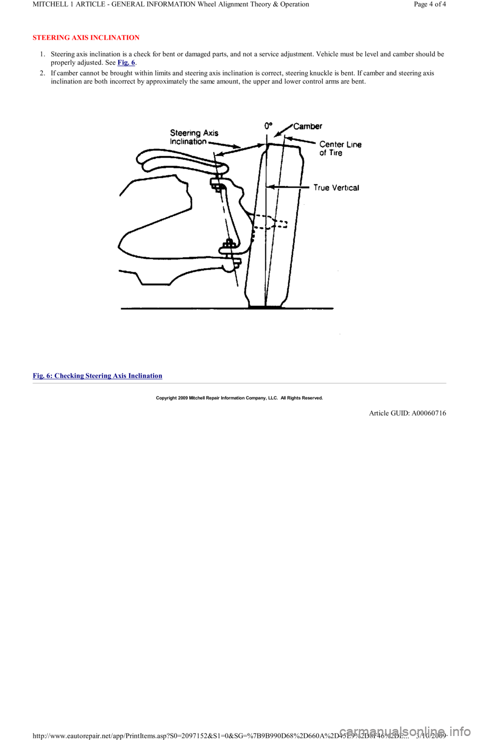
1. Steering axis inclination is a check for bent or damaged parts, and not a service adjustment. Vehicle must be level and camber should be
properly adjusted. See Fig. 6
.
2. If camber cannot be brought within limits and steering axis inclination is correct, steering knuckle is bent. If camber and steering axis
inclination are both incorrect by approximately the same amount, the upper and lower control arms are bent.
Fig. 6: Checking Steering Axis Inclination
Copyr ight 2009 Mitchell Repair Information Company, LLC. All Rights Reserved.
Article GUID: A00060716
Page 4 of 4 MITCHELL 1 ARTICLE - GENERAL INFORMATION Wheel Alignment Theory & Operation
3/10/2009 http://www.eautorepair.net/app/PrintItems.asp?S0=2097152&S1=0&SG=%7B9B990D68%2D660A%2D45E9%2D8F46%2DE
...
Page 305 of 454
Back To Article
GENERAL INFORMATION
Manual Transmission Trouble Shooting
* PLEASE READ THIS FIRST *
INTRODUCTION
There are many times when the transmission is incorrectly blamed for shifting problems or noises that are actually caused by other reasons.
Shift difficulties are frequently caused by conditions outside of the transmission or transaxle. Typical conditions include: shift linkage, shift
cables, alignment of engine to transmission, worn engine mounts or clutch problems. Drive train noises may come from many sources such as
tires, road surfaces, wheel bearings, differentials, engine or exhaust system. Repairing or overhauling transmission will not cure these
problems.
No manufacturer makes a perfectly quiet transmission. Gear rollover noise is present in most constant mesh transmissions and will tend to
disappear when the clutch is disengaged or transmission is placed in gear. If clutch is properly adjusted, clutch release bearing noise will
disappear when release bearing is moved enough to slide release bearing away from pressure plate.
Trouble shooting can be helped by driving vehicle on a smooth level road to help eliminate tire and body noise. Note whether noise occurs on
acceleration, coasting, deceleration or steady driving conditions. Some problems may only occur when transmission is either hot or cold. Gear
lubricant that is too thick can cause hard shifting on cold mornings before engine is warm and vehicle has been driven.
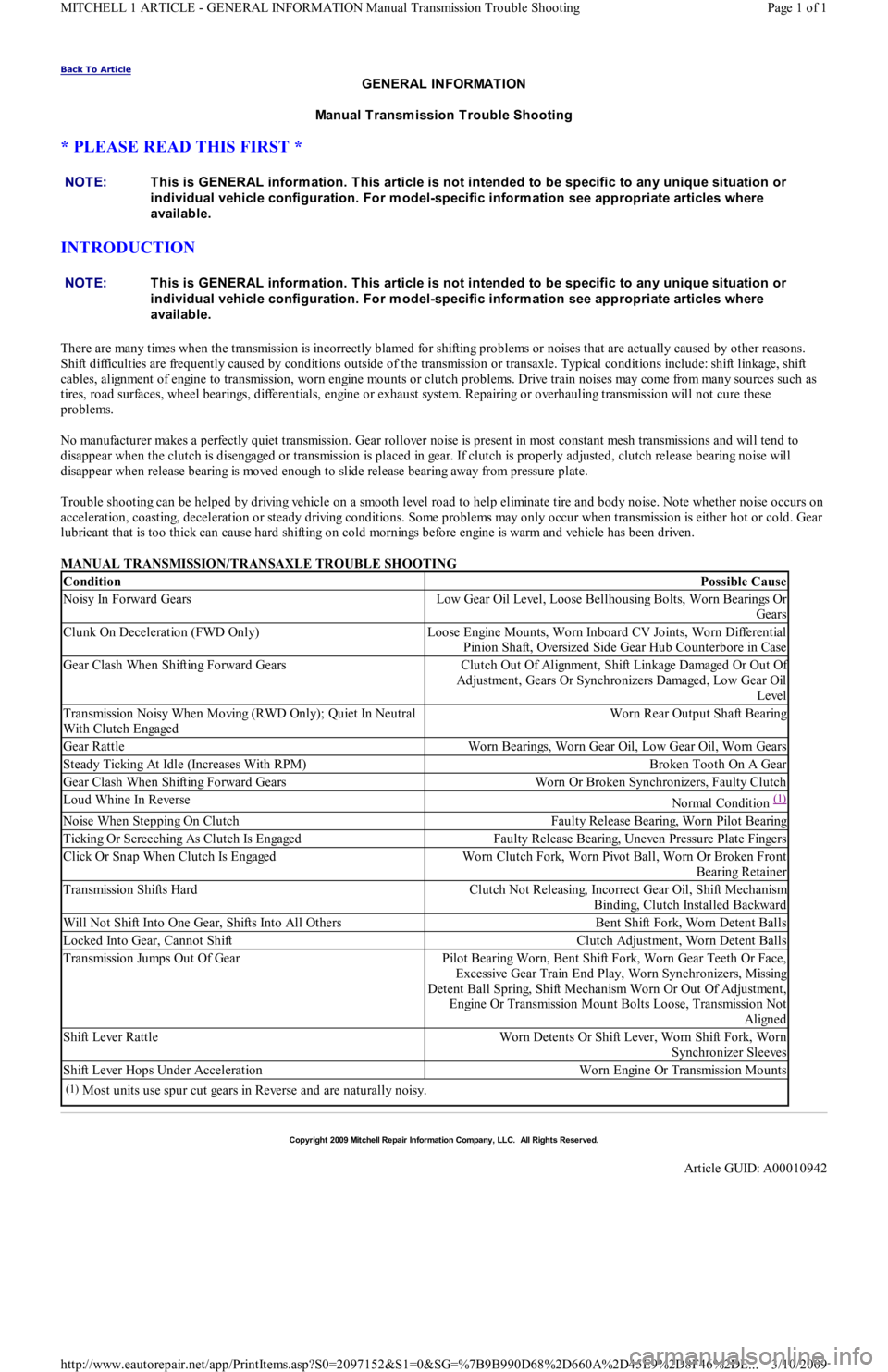
MANUAL TRANSMISSION/TRANSAXLE TROUBLE SHOOTING NOTE:This is GENERAL inform ation. This article is not intended to be specific to any unique situation or
individual vehicle configuration. For m odel-specific inform ation see appropriate articles where
available.
NOTE:This is GENERAL inform ation. This article is not intended to be specific to any unique situation or
individual vehicle configuration. For m odel-specific inform ation see appropriate articles where
available.
ConditionPossible Cause
Noisy In Forward GearsLow Gear Oil Level, Loose Bellhousing Bolts, Worn Bearings Or
Gears
Clunk On Deceleration (FWD Only)Loose Engine Mounts, Worn Inboard CV Joints, Worn Differential
Pinion Shaft, Oversized Side Gear Hub Counterbore in Case
Gear Clash When Shifting Forward GearsClutch Out Of Alignment, Shift Linkage Damaged Or Out Of
Adjustment, Gears Or Synchronizers Damaged, Low Gear Oil
Level
Transmission Noisy When Moving (RWD Only); Quiet In Neutral
With Clutch EngagedWorn Rear Output Shaft Bearing
Gear RattleWorn Bearings, Worn Gear Oil, Low Gear Oil, Worn Gears
Steady Ticking At Idle (Increases With RPM)Broken Tooth On A Gear
Gear Clash When Shifting Forward GearsWorn Or Broken Synchronizers, Faulty Clutch
Loud Whine In ReverseNormal Condition (1)
Noise When Stepping On ClutchFaulty Release Bearing, Worn Pilot Bearing
Ticking Or Screeching As Clutch Is EngagedFaulty Release Bearing, Uneven Pressure Plate Fingers
Click Or Snap When Clutch Is EngagedWorn Clutch Fork, Worn Pivot Ball, Worn Or Broken Front
Bearing Retainer
Transmission Shifts HardClutch Not Releasing, Incorrect Gear Oil, Shift Mechanism
Binding, Clutch Installed Backward
Will Not Shift Into One Gear, Shifts Into All OthersBent Shift Fork, Worn Detent Balls
Locked Into Gear, Cannot ShiftClutch Adjustment, Worn Detent Balls
Transmission Jumps Out Of GearPilot Bearing Worn, Bent Shift Fork, Worn Gear Teeth Or Face,
Excessive Gear Train End Play, Worn Synchronizers, Missing
Detent Ball Spring, Shift Mechanism Worn Or Out Of Adjustment,
Engine Or Transmission Mount Bolts Loose, Transmission Not
Aligned
Shift Lever RattleWorn Detents Or Shift Lever, Worn Shift Fork, Worn
Synchronizer Sleeves
Shift Lever Hops Under AccelerationWorn Engine Or Transmission Mounts
(1)Most units use spur cut gears in Reverse and are naturally noisy.
Copyr ight 2009 Mitchell Repair Information Company, LLC. All Rights Reserved.
Article GUID: A00010942
Page 1 of 1 MITCHELL 1 ARTICLE - GENERAL INFORMATION Manual Transmission Trouble Shooting
3/10/2009 http://www.eautorepair.net/app/PrintItems.asp?S0=2097152&S1=0&SG=%7B9B990D68%2D660A%2D45E9%2D8F46%2DE
...
Page 306 of 454
Back To Article
1991 GENERAL SERVICING
A/C Com pressor Refrigerant Oil Checking
ISOLATING COMPRESSOR
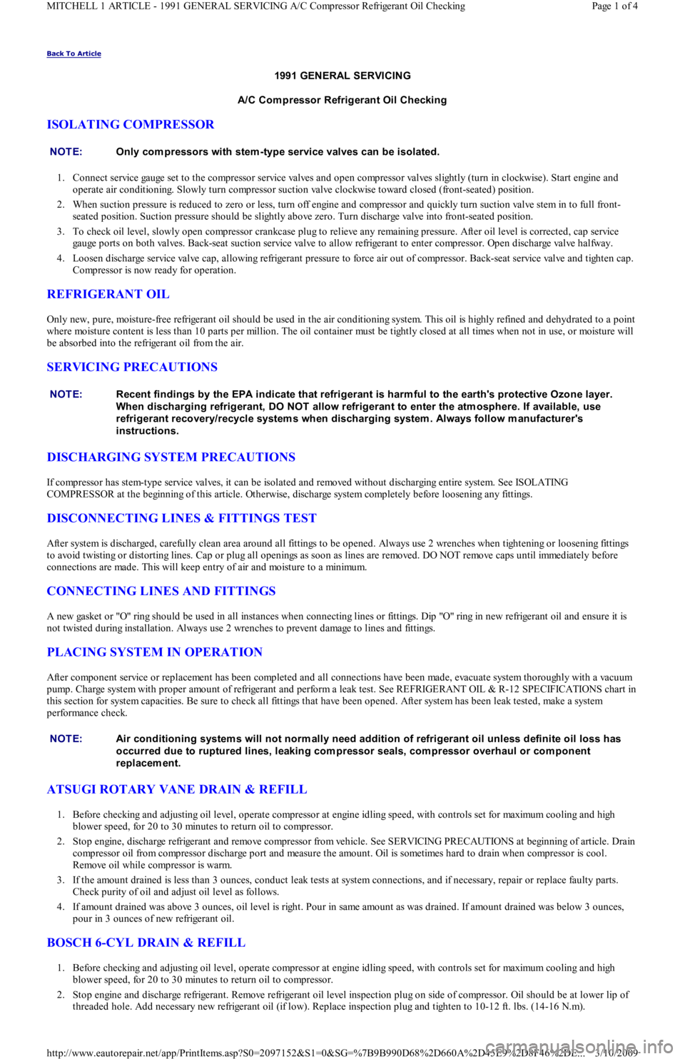
1. Connect service gauge set to the compressor service valves and open compressor valves slightly (turn in clockwise). Start engine and
operate air conditioning. Slowly turn compressor suction valve clockwise toward closed (front-seated) position.
2. When suction pressure is reduced to zero or less, turn off engine and compressor and quickly turn suction valve stem in to full front-
seated position. Suction pressure should be slightly above zero. Turn discharge valve into front-seated position.
3. To check oil level, slowly open compressor crankcase plug to relieve any remaining pressure. After oil level is corrected, cap service
gauge ports on both valves. Back-seat suction service valve to allow refrigerant to enter compressor. Open discharge valve halfway.
4. Loosen discharge service valve cap, allowing refrigerant pressure to force air out of compressor. Back-seat service valve and tighten cap.
Compressor is now ready for operation.
REFRIGERANT OIL
Only new, pure, moisture-free refrigerant oil should be used in the air conditioning system. This oil is highly refined and dehydrated to a point
where moisture content is less than 10 parts per million. The oil container must be tightly closed at all times when not in use, or moisture will
be absorbed into the refrigerant oil from the air.
SERVICING PRECAUTIONS
DISCHARGING SYSTEM PRECAUTIONS
If compressor has stem-type service valves, it can be isolated and removed without discharging entire system. See ISOLATING
COMPRESSOR at the beginning of this article. Otherwise, discharge system completely before loosening any fittings.
DISCONNECTING LINES & FITTINGS TEST
After system is discharged, carefully clean area around all fittings to be opened. Always use 2 wrenches when tightening or loosening fittings
to avoid twisting or distorting lines. Cap or plug all openings as soon as lines are removed. DO NOT remove caps until immediately before
connections are made. This will keep entry of air and moisture to a minimum.
CONNECTING LINES AND FITTINGS
A new gasket or "O" ring should be used in all instances when connecting lines or fittings. Dip "O" ring in new refrigerant oil and ensure it is
not twisted during installation. Always use 2 wrenches to prevent damage to lines and fittings.
PLACING SYSTEM IN OPERATION
After component service or replacement has been completed and all connections have been made, evacuate system thoroughly with a vacuum
pump. Charge system with proper amount of refrigerant and perform a leak test. See REFRIGERANT OIL & R-12 SPECIFICATIONS chart in
this section for system capacities. Be sure to check all fittings that have been opened. After system has been leak tested, make a system
performance check.
ATSUGI ROTARY VANE DRAIN & REFILL
1. Before checking and adjusting oil level, operate compressor at engine idling speed, with controls set for maximum cooling and high
blower speed, for 20 to 30 minutes to return oil to compressor.
2. Stop engine, discharge refrigerant and remove compressor from vehicle. See SERVICING PRECAUTIONS at beginning of article. Drain
compressor oil from compressor discharge port and measure the amount. Oil is sometimes hard to drain when compressor is cool.
Remove oil while compressor is warm.
3. If the amount drained is less than 3 ounces, conduct leak tests at system connections, and if necessary, repair or replace faulty parts.
Check purity of oil and adjust oil level as follows.
4. If amount drained was above 3 ounces, oil level is right. Pour in same amount as was drained. If amount drained was below 3 ounces,
pour in 3 ounces of new refrigerant oil.
BOSCH 6-CYL DRAIN & REFILL
1. Before checking and adjusting oil level, operate compressor at engine idling speed, with controls set for maximum cooling and high
blower speed, for 20 to 30 minutes to return oil to compressor.
2. Stop engine and discharge refrigerant. Remove refrigerant oil level inspection plug on side of compressor. Oil should be at lower lip of
threaded hole. Add necessary new refrigerant oil (if low). Replace inspection plug and tighten to 10-12 ft. lbs. (14-16 N.m). NOTE:Only com pressors with stem -type service valves can be isolated.
NOTE:Recent findings by the EPA indicate that refrigerant is harm ful to the earth's protective Ozone layer.
When discharging refrigerant, DO NOT allow refrigerant to enter the atm osphere. If available, use
refrigerant recovery/recycle system s when discharging system . Always follow m anufacturer's
instructions.
NOTE:Air conditioning system s will not norm ally need addition of refrigerant oil unless definite oil loss has
occurred due to ruptured lines, leaking com pressor seals, com pressor overhaul or com ponent
replacem ent.
Page 1 of 4 MITCHELL 1 ARTICLE - 1991 GENERAL SERVICING A/C Compressor Refrigerant Oil Checking
3/10/2009 http://www.eautorepair.net/app/PrintItems.asp?S0=2097152&S1=0&SG=%7B9B990D68%2D660A%2D45E9%2D8F46%2DE
...
Page 307 of 454
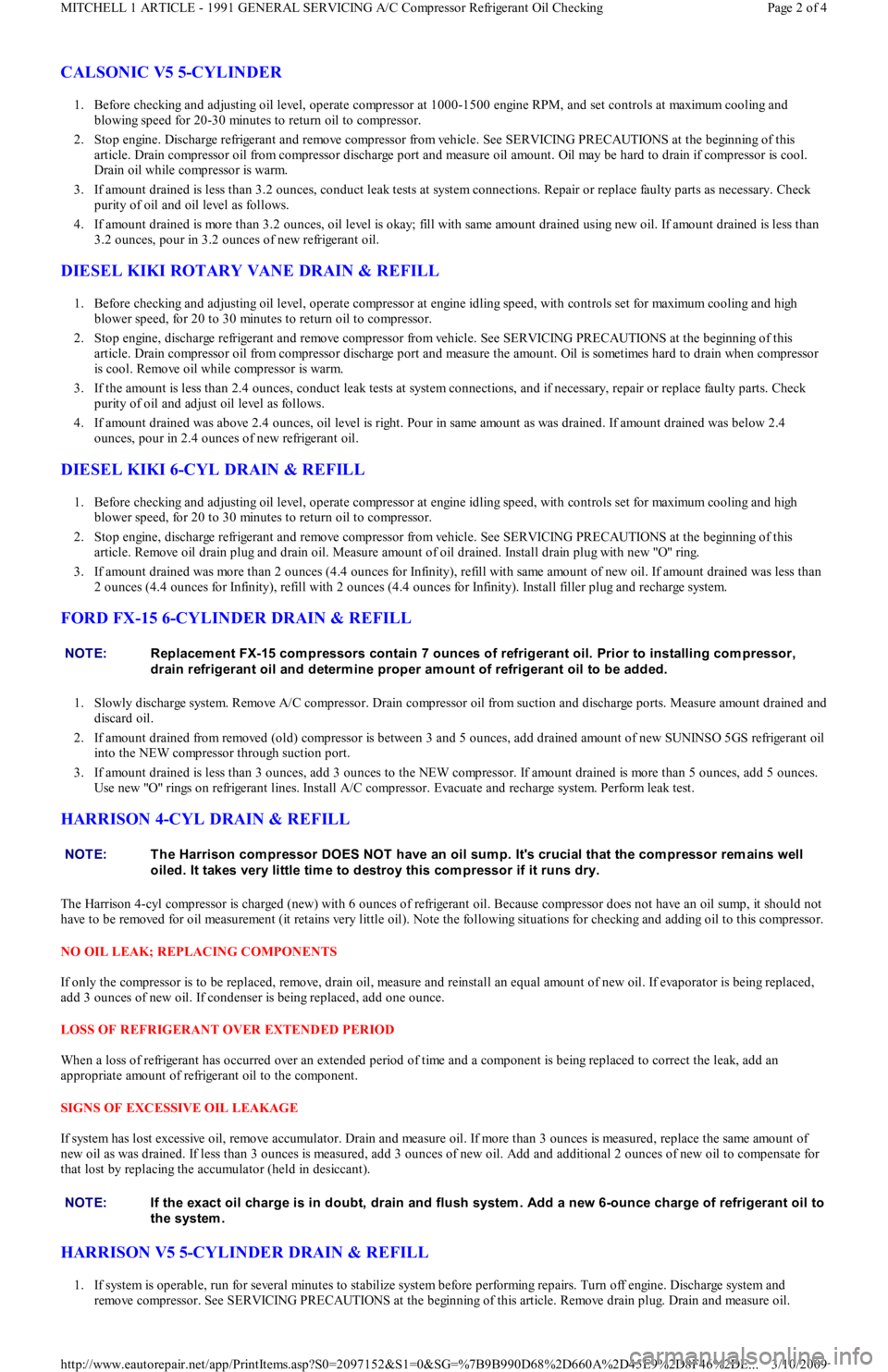
CALSONIC V5 5-CYLINDER
1. Before checking and adjusting oil level, operate compressor at 1000-1500 engine RPM, and set controls at maximum cooling and
blowing speed for 20-30 minutes to return oil to compressor.
2. Stop engine. Discharge refrigerant and remove compressor from vehicle. See SERVICING PRECAUTIONS at the beginning of this
article. Drain compressor oil from compressor discharge port and measure oil amount. Oil may be hard to drain if compressor is cool.
Drain oil while compressor is warm.
3. If amount drained is less than 3.2 ounces, conduct leak tests at system connections. Repair or replace faulty parts as necessary. Check
purity of oil and oil level as follows.
4. If amount drained is more than 3.2 ounces, oil level is okay; fill with same amount drained using new oil. If amount drained is less than
3.2 ounces, pour in 3.2 ounces of new refrigerant oil.
DIESEL KIKI ROTARY VANE DRAIN & REFILL
1. Before checking and adjusting oil level, operate compressor at engine idling speed, with controls set for maximum cooling and high
blower speed, for 20 to 30 minutes to return oil to compressor.
2. Stop engine, discharge refrigerant and remove compressor from vehicle. See SERVICING PRECAUTIONS at the beginning of this
article. Drain compressor oil from compressor discharge port and measure the amount. Oil is sometimes hard to drain when compressor
is cool. Remove oil while compressor is warm.
3. If the amount is less than 2.4 ounces, conduct leak tests at system connections, and if necessary, repair or replace faulty parts. Check
purity of oil and adjust oil level as follows.
4. If amount drained was above 2.4 ounces, oil level is right. Pour in same amount as was drained. If amount drained was below 2.4
ounces, pour in 2.4 ounces of new refrigerant oil.
DIESEL KIKI 6-CYL DRAIN & REFILL
1. Before checking and adjusting oil level, operate compressor at engine idling speed, with controls set for maximum cooling and high
blower speed, for 20 to 30 minutes to return oil to compressor.
2. Stop engine, discharge refrigerant and remove compressor from vehicle. See SERVICING PRECAUTIONS at the beginning of this
article. Remove oil drain plug and drain oil. Measure amount of oil drained. Install drain plug with new "O" ring.
3. If amount drained was more than 2 ounces (4.4 ounces for Infinity), refill with same amount of new oil. If amount drained was less than
2 ounces (4.4 ounces for Infinity), refill with 2 ounces (4.4 ounces for Infinity). Install filler plug and recharge system.
FORD FX-15 6-CYLINDER DRAIN & REFILL
1. Slowly discharge system. Remove A/C compressor. Drain compressor oil from suction and discharge ports. Measure amount drained and
discard oil.
2. If amount drained from removed (old) compressor is between 3 and 5 ounces, add drained amount of new SUNINSO 5GS refrigerant oil
into the NEW compressor through suction port.
3. If amount drained is less than 3 ounces, add 3 ounces to the NEW compressor. If amount drained is more than 5 ounces, add 5 ounces.
Use new "O" rings on refrigerant lines. Install A/C compressor. Evacuate and recharge system. Perform leak test.
HARRISON 4-CYL DRAIN & REFILL
The Harrison 4-cyl compressor is charged (new) with 6 ounces of refrigerant oil. Because compressor does not have an oil sump, it should not
have to be removed for oil measurement (it retains very little oil). Note the following situations for checking and adding oil to this compressor.
NO OIL LEAK; REPLACING COMPONENTS
If only the compressor is to be replaced, remove, drain oil, measure and reinstall an equal amount of new oil. If evaporator is being replaced,
add 3 ounces of new oil. If condenser is being replaced, add one ounce.
LOSS OF REFRIGERANT OVER EXTENDED PERIOD
When a loss of refrigerant has occurred over an extended period of time and a component is being replaced to correct the leak, add an
appropriate amount of refrigerant oil to the component.
SIGNS OF EXCESSIVE OIL LEAKAGE
If system has lost excessive oil, remove accumulator. Drain and measure oil. If more than 3 ounces is measured, replace the same amount of
new oil as was drained. If less than 3 ounces is measured, add 3 ounces of new oil. Add and additional 2 ounces of new oil to compensate for
that lost by replacing the accumulator (held in desiccant).
HARRISON V5 5-CYLINDER DRAIN & REFILL
1. If system is operable, run for several minutes to stabilize system before performing repairs. Turn off engine. Discharge system and
remove compressor. See SERVICING PRECAUTIONS at the beginning of this article. Remove drain plug. Drain and measure oil. NOTE:Replacem ent FX-15 com pressors contain 7 ounces of refrigerant oil. Prior to installing com pressor,
drain refrigerant oil and determ ine proper am ount of refrigerant oil to be added.
NOTE:T he Harrison com pressor DOES NOT have an oil sum p. It's crucial that the com pressor rem ains well
oiled. It takes very little tim e to destroy this com pressor if it runs dry.
NOTE:If the exact oil charge is in doubt, drain and flush system . Add a new 6-ounce charge of refrigerant oil to
the system .
Page 2 of 4 MITCHELL 1 ARTICLE - 1991 GENERAL SERVICING A/C Compressor Refrigerant Oil Checking
3/10/2009 http://www.eautorepair.net/app/PrintItems.asp?S0=2097152&S1=0&SG=%7B9B990D68%2D660A%2D45E9%2D8F46%2DE
...
Page 308 of 454
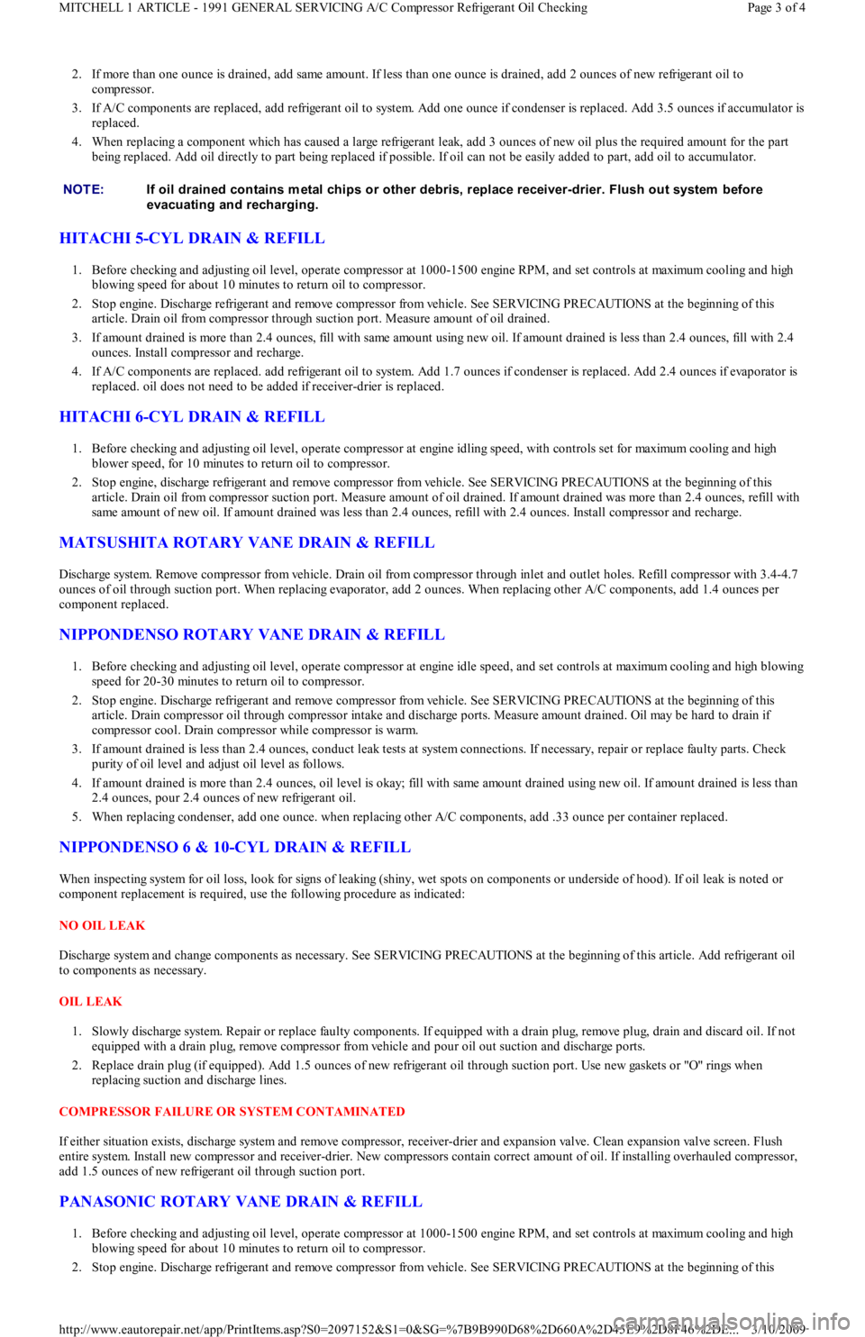
2. If more than one ounce is drained, add same amount. If less than one ounce is drained, add 2 ounces of new refrigerant oil to
compressor.
3. If A/C components are replaced, add refrigerant oil to system. Add one ounce if condenser is replaced. Add 3.5 ounces if accumu l at o r is
replaced.
4. When replacing a component which has caused a large refrigerant leak, add 3 ounces of new oil plus the required amount for the part
being replaced. Add oil directly to part being replaced if possible. If oil can not be easily added to part, add oil to accumulator.
HITACHI 5-CYL DRAIN & REFILL
1. Before checking and adjusting oil level, operate compressor at 1000-1500 engine RPM, and set controls at maximum cooling and high
blowing speed for about 10 minutes to return oil to compressor.
2. Stop engine. Discharge refrigerant and remove compressor from vehicle. See SERVICING PRECAUTIONS at the beginning of this
article. Drain oil from compressor through suction port. Measure amount of oil drained.
3. If amount drained is more than 2.4 ounces, fill with same amount using new oil. If amount drained is less than 2.4 ounces, fill with 2.4
ounces. Install compressor and recharge.
4. If A/C components are replaced. add refrigerant oil to system. Add 1.7 ounces if condenser is replaced. Add 2.4 ounces if evaporator is
replaced. oil does not need to be added if receiver-drier is replaced.
HITACHI 6-CYL DRAIN & REFILL
1. Before checking and adjusting oil level, operate compressor at engine idling speed, with controls set for maximum cooling and high
blower speed, for 10 minutes to return oil to compressor.
2. Stop engine, discharge refrigerant and remove compressor from vehicle. See SERVICING PRECAUTIONS at the beginning of this
article. Drain oil from compressor suction port. Measure amount of oil drained. If amount drained was more than 2.4 ounces, refill with
same amount of new oil. If amount drained was less than 2.4 ounces, refill with 2.4 ounces. Install compressor and recharge.
MATSUSHITA ROTARY VANE DRAIN & REFILL
Discharge system. Remove compressor from vehicle. Drain oil from compressor through inlet and outlet holes. Refill compressor with 3.4-4.7
ounces of oil through suction port. When replacing evaporator, add 2 ounces. When replacing other A/C components, add 1.4 ounces per
component replaced.
NIPPONDENSO ROTARY VANE DRAIN & REFILL
1. Before checking and adjusting oil level, operate compressor at engine idle speed, and set controls at maximum cooling and high blowing
speed for 20-30 minutes to return oil to compressor.
2. Stop engine. Discharge refrigerant and remove compressor from vehicle. See SERVICING PRECAUTIONS at the beginning of this
article. Drain compressor oil through compressor intake and discharge ports. Measure amount drained. Oil may be hard to drain if
compressor cool. Drain compressor while compressor is warm.
3. If amount drained is less than 2.4 ounces, conduct leak tests at system connections. If necessary, repair or replace faulty parts. Check
purity of oil level and adjust oil level as follows.
4. If amount drained is more than 2.4 ounces, oil level is okay; fill with same amount drained using new oil. If amount drained is less than
2.4 ounces, pour 2.4 ounces of new refrigerant oil.
5. When replacing condenser, add one ounce. when replacing other A/C components, add .33 ounce per container replaced.
NIPPONDENSO 6 & 10-CYL DRAIN & REFILL
When inspecting system for oil loss, look for signs of leaking (shiny, wet spots on components or underside of hood). If oil leak is noted or
component replacement is required, use the following procedure as indicated:
NO OIL LEAK
Discharge system and change components as necessary. See SERVICING PRECAUTIONS at the beginning of this article. Add refrigerant oil
to components as necessary.
OIL LEAK
1. Slowly discharge system. Repair or replace faulty components. If equipped with a drain plug, remove plug, drain and discard oil. If not
equipped with a drain plug, remove compressor from vehicle and pour oil out suction and discharge ports.
2. Replace drain plug (if equipped). Add 1.5 ounces of new refrigerant oil through suction port. Use new gaskets or "O" rings when
replacing suction and discharge lines.
COMPRESSOR FAILURE OR SYSTEM CONTAMINATED
If either situation exists, discharge system and remove compressor, receiver-drier and expansion valve. Clean expansion valve screen. Flush
entire system. Install new compressor and receiver-drier. New compressors contain correct amount of oil. If installing overhauled compressor,
add 1.5 ounces of new refrigerant oil through suction port.
PANASONIC ROTARY VANE DRAIN & REFILL
1. Before checking and adjusting oil level, operate compressor at 1000-1500 engine RPM, and set controls at maximum cooling and high
blowing speed for about 10 minutes to return oil to compressor.
2. Stop engine. Discharge refrigerant and remove compressor from vehicle. See SERVICING PRECAUTIONS at the beginning of this NOTE:If oil drained contains m etal chips or other debris, replace receiver-drier. Flush out system before
evacuating and recharging.
Page 3 of 4 MITCHELL 1 ARTICLE - 1991 GENERAL SERVICING A/C Compressor Refrigerant Oil Checking
3/10/2009 http://www.eautorepair.net/app/PrintItems.asp?S0=2097152&S1=0&SG=%7B9B990D68%2D660A%2D45E9%2D8F46%2DE
...
Page 309 of 454
article. Drain oil from compressor through suction and discharge ports. Measure amount of oil drained. If amount drained is more than
2.4 ounces, fill with same amount using new oil. If amount drained is less than 2.4 ounces, fill with 2.4 ounces. Install compressor and
recharge.
3. If A/C components are replaced, add refrigerant oil to system. Add 1.4 ounces if condenser is replaced. Add 2 ounces if the evaporator
is replaced. Oil does not need to be added if receiver-drier is replaced.
SANDEN SCROLL DRAIN & REFILL
Discharge system. Remove compressor from vehicle. Drain oil from compressor through inlet and outlet holes. Refill compressor with 2.8
ounces of oil through suction port. When replacing condenser, add .5 ounce. When replacing evaporator, add 1.7 ounces. When replacing
other A/C components, add .5 ounce per component replaced.
SANDEN 5-CYL DRAIN & REFILL
1. Discharge system. Remove compressor belt and loosen mounting bolts. Rotate compressor in brackets until filler plug is at top. Clean
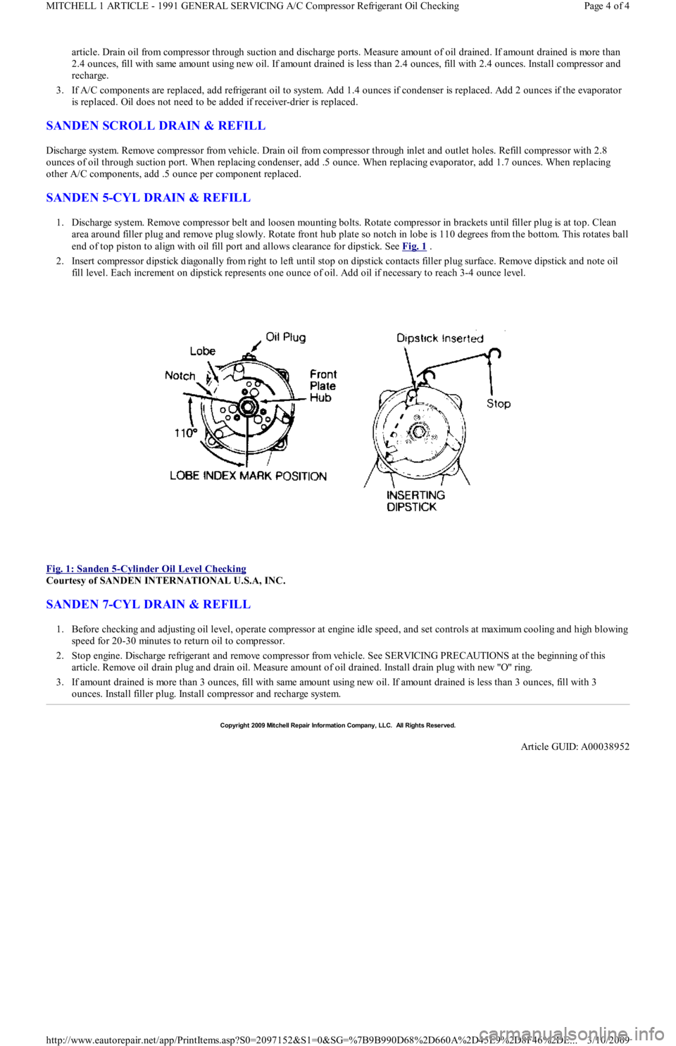
area around filler plug and remove plug slowly. Rotate front hub plate so notch in lobe is 110 degrees from the bottom. This rotates ball
end of top piston to align with oil fill port and allows clearance for dipstick. See Fig. 1
.
2. Insert compressor dipstick diagonally from right to left until stop on dipstick contacts filler plug surface. Remove dipstick and note oil
fill level. Each increment on dipstick represents one ounce of oil. Add oil if necessary to reach 3-4 ounce level.
Fig. 1: Sanden 5
-Cylinder Oil Level Checking
Courtesy of SANDEN INTERNATIONAL U.S.A, INC.
SANDEN 7-CYL DRAIN & REFILL
1. Before checking and adjusting oil level, operate compressor at engine idle speed, and set controls at maximum cooling and high blowing
speed for 20-30 minutes to return oil to compressor.
2. Stop engine. Discharge refrigerant and remove compressor from vehicle. See SERVICING PRECAUTIONS at the beginning of this
article. Remove oil drain plug and drain oil. Measure amount of oil drained. Install drain plug with new "O" ring.
3. If amount drained is more than 3 ounces, fill with same amount using new oil. If amount drained is less than 3 ounces, fill with 3
ounces. Install filler plug. Install compressor and recharge system.
Copyr ight 2009 Mitchell Repair Information Company, LLC. All Rights Reserved.
Article GUID: A00038952
Page 4 of 4 MITCHELL 1 ARTICLE - 1991 GENERAL SERVICING A/C Compressor Refrigerant Oil Checking
3/10/2009 http://www.eautorepair.net/app/PrintItems.asp?S0=2097152&S1=0&SG=%7B9B990D68%2D660A%2D45E9%2D8F46%2DE
...
Page 310 of 454
Back To Article
GENERAL SERVICING
1991 Ford Com pressor Overhaul
REMOVAL & INSTALLATION
FORD FS-6 6-CYL CLUTCH ASSEMBLY
Removal
1. Using Spanner (T70P-4067-A), remove compressor shaft nut. Thread Hub Remover (T80L-19703-B) into clutch plate. Tighten center
bolt in hub remover to remove clutch plate and shims.
2. Remove snap ring. Remove pulley assembly from compressor. If assembly cannot be easily removed, place Shaft Protector (T80L-
19703-G) over shaft. Using Puller (D81P-19703-B), remove pulley assembly. Remove clutch coil retaining snap ring. Remove clutch
coil.
3. If bearing replacement is required, place pulley on Support (T80L-19703-E). Drive bearing from pulley using Bearing Remover (T80L-
19703-J).
Installation
1. If bearing is to be installed, place pulley on support. Using Bearing Installer (T80L-19703-C), drive bearing into pulley. Stake pulley in
4 places to retain bearing.
2. Install clutch coil on compressor so locating pin on compressor engages with hole in clutch coil. Install snap ring. Using hammer and
Pulley Installer (T80L-19703-J), tap pulley assembly on compressor.
3. Install snap ring with beveled side away from compressor. Using Clutch Plate Installer (T80L-19703-F), install clutch plate and shims.
Install and tighten compressor shaft nut to 10-14 ft. lbs. (14-19 N.m).
4. Using feeler gauge, measure air gap between clutch plate and pulley surface in 3 locations around pulley. Rotate pulley 180 degrees and
recheck clearance. Proper clearance is .021-.036" (.05-.91 mm). Adjust shim thickness to obtain correct clearance.
FORD FS-6 6-CYL SHAFT SEAL
Removal
1. Discharge system using approved refrigerant recovery/recycling equipment and remove compressor. Drain oil from compressor and
record amount for reassembly.
2. Remove clutch assembly. See FORD FS-6 6-CYL CLUTCH ASSEMBLY R & I in this article. Ensure compressor outer surface is clean.
Attach compressor on Clamp & Holding Fixture (T81P-19623-D). Place fixture in vise.
3. Using Key Remover (T81P-19623-NH), remove key from compressor shaft. Remove front head-to-compressor retaining bolts. Remove
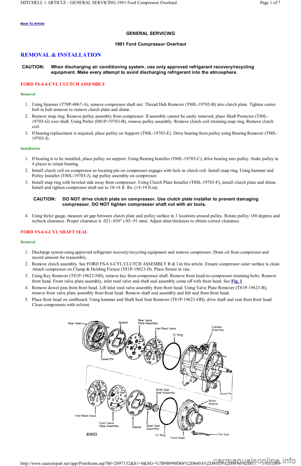
front head. Front valve plate assembly, inlet reed valve and shaft seal assembly come off with front head. See Fig. 1
.
4. Remove dowel pins from front head. Lift inlet reed valve assembly from front head. Using Valve Plate Remover (T81P-19623-B),
remove front valve plate assembly from front head. Remove shaft seal assembly and felt seal from front head.
5. Place front head on cardboard. Using hammer and Shaft Seal Seat Remover (T81P-19623-OH), drive shaft seal seat from front head.
Clean components with solvent. CAUT ION: When discharging air conditioning system , use only approved refrigerant recovery/recycling
equipm ent. Make every attem pt to avoid discharging refrigerant into the atm osphere.
CAUT ION: DO NOT drive clutch plate on com pressor. Use clutch plate installer to prevent dam aging
com pressor. DO NOT tighten com pressor shaft nut with air tools.
Page 1 of 7 MITCHELL 1 ARTICLE - GENERAL SERVICING 1991 Ford Compressor Overhaul
3/10/2009 http://www.eautorepair.net/app/PrintItems.asp?S0=2097152&S1=0&SG=%7B9B990D68%2D660A%2D45E9%2D8F46%2DE
...