FORD MUSTANG 1969 Volume One Chassis
Manufacturer: FORD, Model Year: 1969, Model line: MUSTANG, Model: FORD MUSTANG 1969Pages: 413, PDF Size: 75.81 MB
Page 251 of 413
05-01-04
Drive Shaft
05-01-04
tralizing.
If a
vibration exists,
the
drive shaft should
be
disconnected
from
the
axle, rotated 180 degrees
and
reinstalled.
3.
Install
the
U-blots
and
nuts that
attach
the
U-joint
to the
drive pinion
flange. Torque
the
U-bolt nuts
to
specification.
On
vehicles equipped
with
a
double cardan joint, install
the
rear joint-to-drive pinion flange
at-
taching bolts. Torque
the
bolts
to spe-
cification.
YOKE
C1773-A
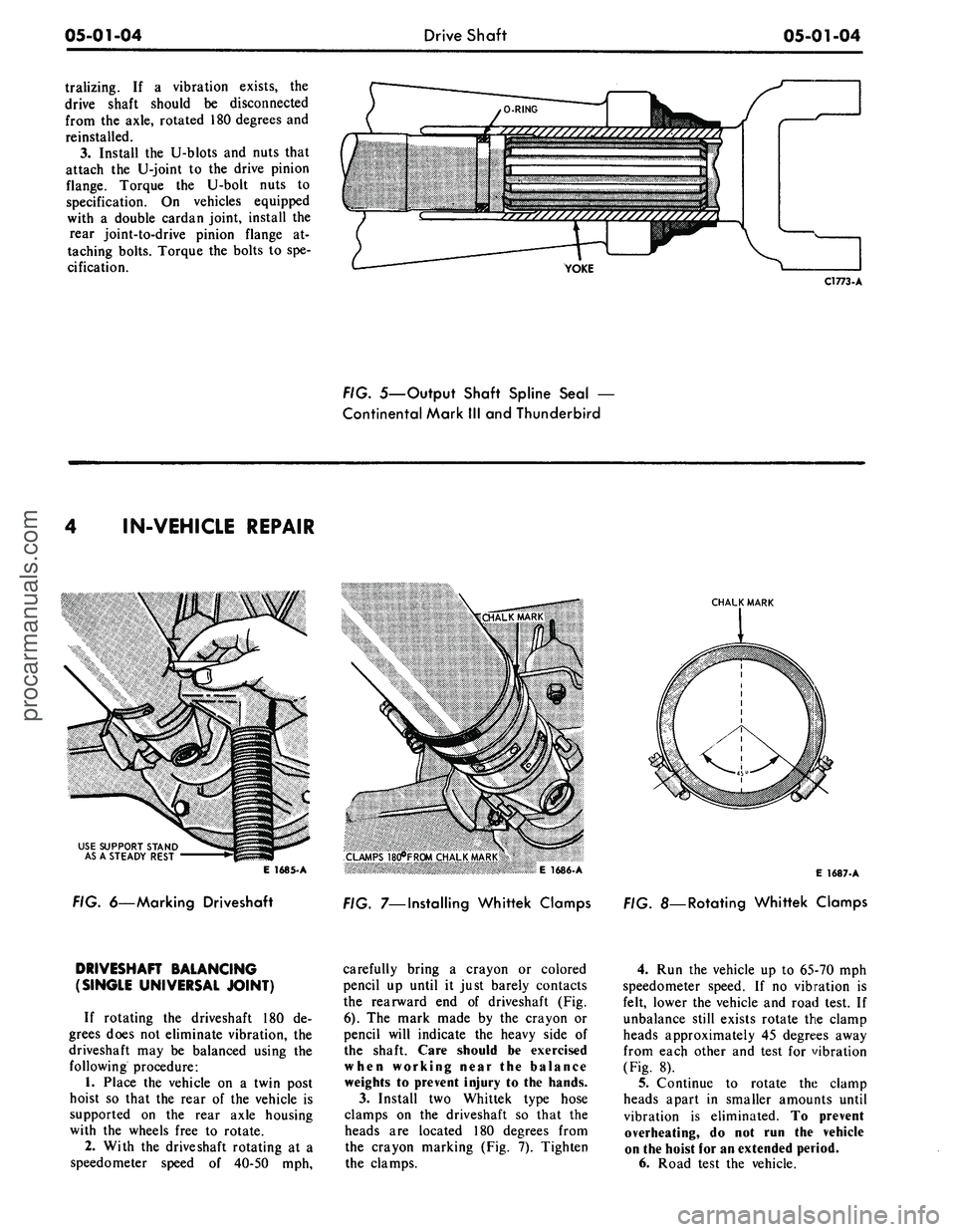
FIG. 5—Output Shaft Spline Seal
—
Continental Mark
III
and Thunderbird
IN-VEHICLE REPAIR
USE SUPPORT STAND
AS
A
STEADY REST
E 1685-A
FIG. 6—Marking Driveshaft
CHALK MARK
CLAMPS 18d*FR0M CHALK MARK
*« >
E 1686-A
FIG. 7—Installing Whittek Clamps
E
1687-
A
. 8—Rotating Whittek Clamps
DRIVESHAFT BALANCING
(SINGLE UNIVERSAL JOINT)
If rotating
the
driveshaft
180 de-
grees does
not
eliminate vibration,
the
driveshaft
may be
balanced using
the
following procedure:
1.
Place
the
vehicle
on a
twin post
hoist
so
that
the
rear
of the
vehicle
is
supported
on the
rear axle housing
with
the
wheels free
to
rotate.
2.
With
the
driveshaft rotating
at a
speedometer speed
of
40-50
mph,
carefully bring
a
crayon
or
colored
pencil
up
until
it
just barely contacts
the rearward
end of
driveshaft
(Fig.
6).
The
mark made
by the
crayon
or
pencil will indicate
the
heavy side
of
the shaft. Care should
be
exercised
when working near
the
balance
weights
to
prevent injury
to the
hands.
3.
Install
two
Whittek type hose
clamps
on the
driveshaft
so
that
the
heads
are
located
180
degrees from
the crayon marking
(Fig. 7).
Tighten
the clamps.
4.
Run the
vehicle
up to
65-70
mph
speedometer speed.
If no
vibration
is
felt, lower
the
vehicle
and
road test.
If
unbalance still exists rotate
the
clamp
heads approximately
45
degrees away
from each other
and
test
for
vibration
(Fig.
8).
5.
Continue
to
rotate
the
clamp
heads apart
in
smaller amounts until
vibration
is
eliminated.
To
prevent
overheating,
do not run the
vehicle
on
the
hoist
for an
extended period.
6. Road test
the
vehicle.procarmanuals.com
Page 252 of 413
05-01-05
Drive Shaft
05-01-05
MAJOR REPAIR OPERATIONS
DISASSEMBLY (SINGLE
UNIVERSAL JOINT —
FORD DESIGN)
1.
Place the drive shaft in a vise
being careful not to damage it.
2.
Remove the snap rings that re-
tain the bearings in the slip yoke and
in the drive shaft.
3.
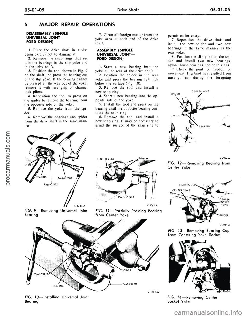
Position the tool shown in Fig. 9
on the shaft and press the bearing out
of the slip yoke. If the bearing cannot
be pressed all the way out of the yoke,
remove it with vise grip or channel
lock pliers.
4.
Reposition the tool to press on
the spider to remove the bearing from
the opposite side of the yoke.
5.
Remove the yoke from the spi-
der.
6. Remove the bearings and spider
from the drive shaft in the same man-
ner.
C 1781-A
FIG. 9—Removing Universal Joint
Bearing
7.
Clean all foreign matter from the
yoke area at each end of the drive
shaft.
ASSEMBLY (SINGLE
UNIVERSAL JOINT-
FORD DESIGN)
1.
Start a new bearing into the
yoke at the rear of the drive shaft.
2.
Position the spider in the rear
yoke and press the bearing 1/4 inch
below the surface (Fig. 10).
3.
Remove the tool and install a
new snap ring.
4.
Start a new bearing into the op-
posite side of the yoke.
5.
Install the tool and press on the
bearing until the opposite bearing con-
tacts the snap ring.
6. Remove the tool and install a
new snap ring. It may be necessary to
grind the surface of the snap ring to
CENTER YOKE
Adapter
C 2062-A
FIG. 11— Partially Pressing Bearing
from Center Yoke
Tool-CJ91B
C 1782-A
FIG. 10—Installing Universal Joint
Bearing
permit easier entry.
7.
Reposition the drive shaft and
install the new spider and two new
bearings in the same manner as the
rear yoke.
8. Position the slip yoke on the spi-
der and install two new bearings,
nylon thrust bearings and snap rings.
9. Check the joint for freedom of
movement. If a bind has resulted from
misalignment during the foregoing
SPIDER
C206J-A
FIG. 12—Removing Bearing from
Center Yoke
BEARING CUP
SPIDER
C 2064-A
FIG. 13—Removing Bearing Cup
from Centering Yoke Socket
C 2065-A
FIG.
14
— Removing Center
Socket Yokeprocarmanuals.com
Page 253 of 413
05-01-06
Drive Shaft
05-01-06
procedures, a sharp rap on the yokes
with a brass hammer will seat the
bearings needles and usually provide
freedom of movement. Care must be
taken to support the shaft end during
this operation, as well as preventing
blows to the bearings themselves. Do
not install the drive shaft unless the
universal joints are free of bind.
DISASSEMBLY (DOUBLE
CARDAN JOINT — LINCOLN
CONTINENTAL — DANA DESIGN)
1.
Mark the position of the spiders,
the center yoke, and the centering
socket yoke as related to the stud
yoke which is welded to the front of
the drive shaft tube. The spiders must
be assembled with the bosses in their
original position to provide proper
clearance.
2.
Remove the snap rings that se-
cure the bearings in the front of the
center yoke.
3.
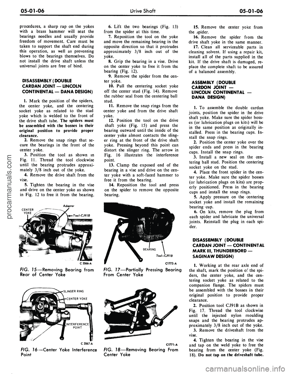
Position the tool as shown in
Fig. 11. Thread the tool clockwise
until the bearing protrudes approxi-
mately 3/8 inch out of the yoke.
4.
Remove the drive shaft from the
vise.
5.
Tighten the bearing in the vise
and drive on the center yoke as shown
in Fig. 12 to free it from the bearing.
CENTER
YOKE
C 2066-A
FIG. 15—Removing Bearing from
Rear of Center Yoke
SLINGER RING
CENTER YOKE
6. Lift the two bearings (Fig. 13)
from the spider at this time.
7.
Reposition the tool on the yoke
and move the remaining bearing in the
opposite direction so that it protrudes
approximately 3/8 inch out of the
yoke.
8. Grip the bearing in a vise. Drive
on the center yoke to free it from the
bearing (Fig. 12).
9. Remove the spider from the cen-
ter yoke.
10.
Pull the centering socket yoke
off the center stud (Fig. 14). Remove
the rubber seal from the centering ball
stud.
11.
Remove the snap rings from the
center yoke and from the drive shaft
yoke.
12.
Position the tool on the drive
shaft yoke (Fig. 15) and press the
bearing outward until the inside of the
center yoke almost contacts the sling-
er ring at the front of the drive shaft
yoke. Pressing beyond this point can
distort the slinger ring. The arrow in
Fig. 16 illustrates the interference
point.
13.
Clamp the exposed end of the
bearing in a vise and drive on the cen-
ter yoke with a soft-faced hammer to
free it from the bearing.
14.
Reposition the tool and press
on the spider to remove the opposite
bearing.
Tool-CJ91B
C1772-A
FIG. 17—Partially Pressing Bearing
From Center Yoke
C 2067-A
FIG. 16—Center Yoke Interference
Point
C1771-A
FIG. 18—Removing Bearing From
Center Yoke
15.
Remove the center yoke from
the spider.
16.
Remove the spider from the
drive shaft yoke in the same manner.
17.
Clean all serviceable parts in
cleaning solvent. If using a repair kit,
install all of the parts supplied in the
kit. If the drive shaft is damaged, re-
place the complete shaft to be assured
of a balanced assembly.
ASSEMBLY (DOUBLE
CARDON JOINT —
LINCOLN CONTINENTAL —
DANA DESIGN)
1.
To assemble the double cardan
joints,
position the spider in the drive
shaft yoke. Make sure the spider boss-
es (or lubrication plugs on kits) will be
in the same position as originally in-
stalled. Press in the bearing cups. In-
stall the snap rings.
2.
Position the center yoke over the
spider ends and press in the bearing
cups.
Install the snap rings.
3.
Install a new seal on the cen-
tering ball stud. Position the centering
socket yoke on the stud.
4.
Place the front spider in the cen-
ter yoke. Make sure the spider bosses
(or lubrication plugs on kits) are prop-
erly positioned. Press in the bearing
cups and install the snap rings.
5.
Apply pressure on the centering
socket yoke and install the remaining
bearing cup.
6. On kits, remove the plug from
each spider and lubricate the universal
joints.
Reinstall the plug in each spi-
der.
DISASSEMBLY (DOUBLE
CARDAN JOINT — CONTINENTAL
MARK III, THUNDERBORD —
SAGINAW DESIGN)
1.
Working at the rear axle end of
the shaft, mark the position of the spi-
ders,
the center yoke, and the cen-
tering socket yoke as related to the
companion flange. The spiders must
be assembled with the bosses in their
original position to provide proper
clearance.
2.
Position tool CJ91B as shown in
Fig. 17. Thread the tool clockwise
until the injected nylon moulding
snaps and the bearing protrudes ap-
proximately 3/8 inch out of the yoke.
3.
Remove the driveshaft from the
vise.
4.
Tighten the bearing in the vise
and tap on the weld yoke to free the
bearing from the center yoke (Fig.
18).
Do not tap on the driveshaft tube.procarmanuals.com
Page 254 of 413
05-01-07
Drive Shaft
05-01-07
5.
Reposition tool CJ91B on the
yoke and force the opposite bearing
outward and remove it.
6. Position the tool on one of the
remaining bearings and force it out-
ward approximately 3/8 inch.
7.
Grip the bearing in the vise and
tap on the weld yoke to free the bear-
ing from the center yoke. Do not tap
on the driveshaft tube.
8. Reposition the tool on the yoke
to press out the remaining bearing.
9. Remove the spider from the cen-
ter yoke.
10.
Remove the bearings from the
driveshaft yoke as outlined above and
remove the spider from the yoke.
11.
Insert a screwdriver into the
centering ball socket located in the
companion flange and pry out the
rubber seal. Remove the retainer, three
piece ball seat, washer and spring
from the ball socket.
12.
Inspect the centering ball socket
assembly for worn or damaged parts.
If any damage is evident replace the
entire assembly.
13.
Repeat Steps 1 through 12 to
disassemble the transmission end of
the driveshaft.
ASSEMBLY (DOUBLE
CARDAN JOINT — CONTINENTAL
MARK III, THUNDERBIRD —
SAGINAW DESIGN)
1.
Working at the rear axle end of
the driveshaft, insert the spring, wash-
er, three piece ball seat and retainer
into the ball socket.
2.
Using a suitable tool, install the
centering ball socket seal.
3.
Position the spider in the drive-
shaft yoke. Make sure the spider
bosses are in the same position as
originally installed. Press in the bear-
ing cups with tool CJ91B. Install the
internal snap rings provided in the re-
pair kit.
4.
Position the center yoke over the
spider ends and press in the bearing
cups.
Install the snap rings.
5.
Install the spider in the compan-
ion flange yoke. Make sure the spider
bosses are. in the same position as
originally installed. Press on the bear-
ing cups and install the snap rings.
6. Position the center yoke over the
spider ends and press on the bearing
cups.
Install the snap rings.
7.
Repeat steps 1 through 6 to as-
semble the transmission end of the
driveshaft.procarmanuals.com
Page 255 of 413
05-02-01
General Clutch Service
05-02-01
PART
5-2
General Clutch Service
COMPONENT INDEX
MODEL APPLICATION
3
a>
1
o>
il
•U
i
!-
II
CLUTCH DISC
Cleaning and Inspection
02-04
02-04
02-04
02-04
02-04
02-04
02-04
02-04
N/A
N/A
N/A
CHECKING FLYWHEEL HOUSING
ALIGNMENT
02-01
02-01
02-01
02-01
02-01
02-01
02-01
02-01
N/A
N/A
N/A
CORRECTING FLYWHEEL HOUSING
ALIGNMENT
02-03
02-03
02-03
02-03
02-03
02-03
02-03
02-03
N/A
N/A
N/A
PILOT BUSHING
Cleaning and Inspection
02-04
02-04
02-04
02-04
02-04
02-04
02-04
02-04
N/A
N/A
N/A
PRESSURE PLATE AND COVER
Cleaning and Inspection
02-04
02-04
02-04
02-04
02-04
02-04
02-04
02-04
N/A
N/A
N/A
RELEASE BEARING
Cleaning and Inspection
02-04
02-04
02-04
02-04
02-04
02-04
02-04
02-04
N/A
N/A
N/A
A page number indicates that the item is for the vehicle listed at the head of the column.
N/A indicates that the item is not applicable to the vehicle listed.
l
FLYWHEEL HOUSING ALIGNMENT
Alignment of the flywheel housing
bore and rear face with the engine
should be checked as a possible cause
of any of the following troubles- ex-
cessive transmission gear wear, ..ans-
mission jumping out of gear, especial-
ly third gear, drive line vibration, ex-
cessive pilot bushing wear, noisy re-
lease bearing, or excessive clutch spin
time.
INSPECTION
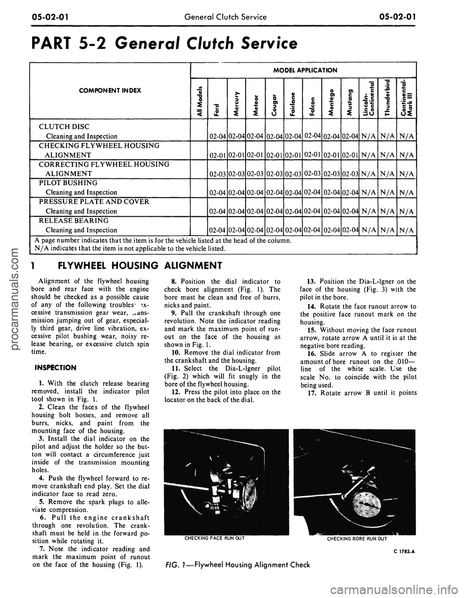
1. With the clutch release bearing
removed, install the indicator pilot
tool shown in Fig. 1.
2.
Clean the faces of the flywheel
housing bolt bosses, and remove all
burrs, nicks, and paint from the
mounting face of the housing.
3.
Install the dial indicator on the
pilot and adjust the holder so the but-
ton will contact a circumference just
inside of the transmission mounting
holes.
4.
Push the flywheel forward to re-
move crankshaft end play. Set the dial
indicator face to read zero.
5.
Remove the spark plugs to alle-
viate compression.
6. Pull the engine crankshaft
through one revolution. The crank-
shaft must be held in the forward po-
sition while rotating it.
7. Note the indicator reading and
mark the maximum point of runout
on the face of the housing (Fig. 1).
8. Position the dial indicator to
check bore alignment (Fig. 1). The
bore must be clean and free of burrs,
nicks and paint.
9. Pull the crankshaft through one
revolution. Note the indicator reading
and mark the maximum point of run-
out on the face of the housing as
shown in Fig. 1.
10.
Remove the dial indicator from
the crankshaft and the housing.
11.
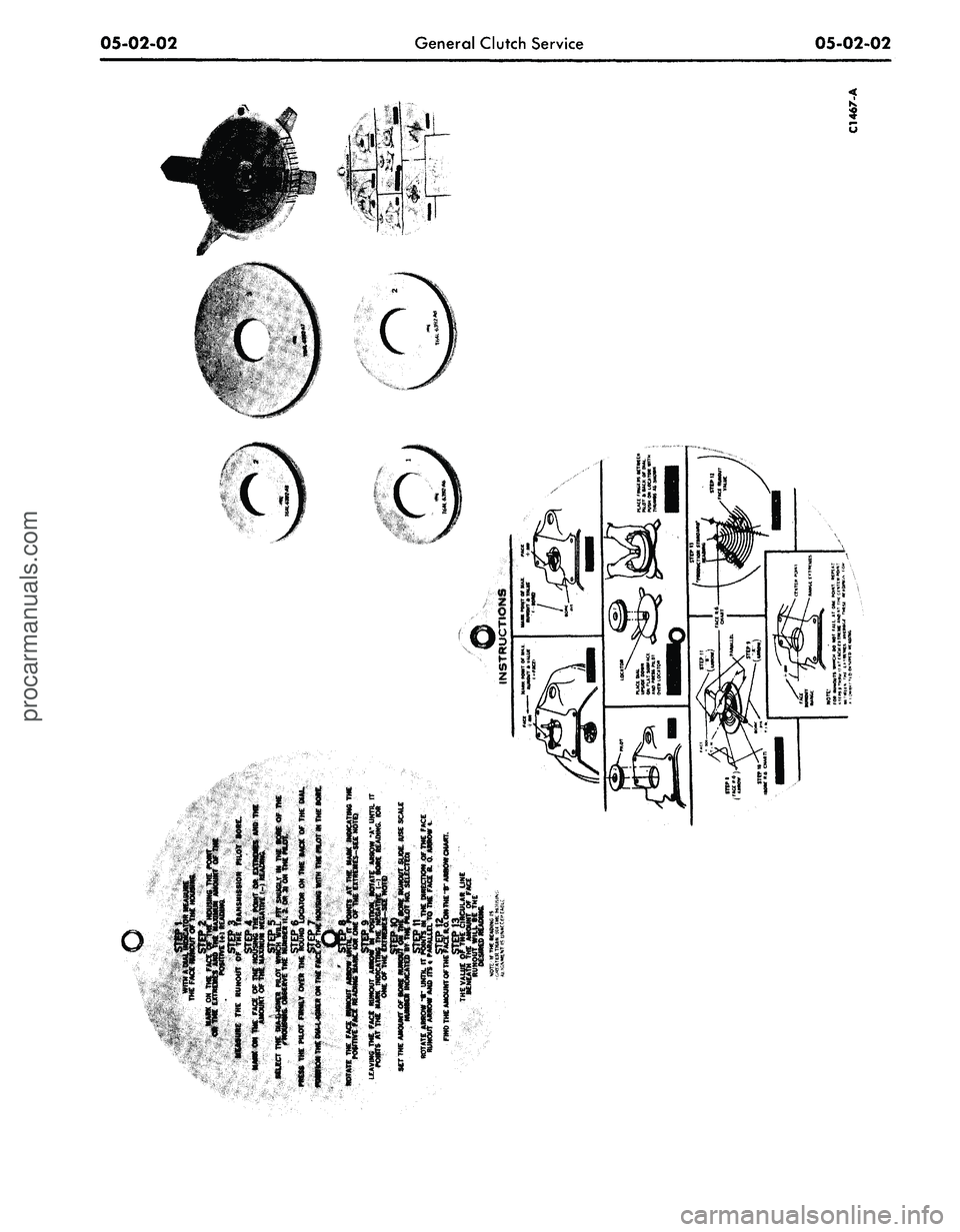
Select the Dia-L-lgner pilot
(Fig. 2) which will fit snugly in the
bore of the flywheel housing.
12.
Press the pilot into place on the
locator on the back of the dial.
13.
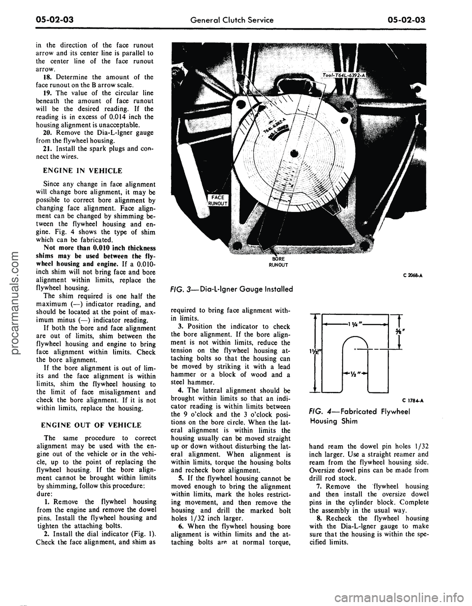
Position the Dia-L-lgner on the
face of the housing (Fig. 3) with the
pilot in the bore.
14.
Rotate the face runout arrow to
the positive face runout mark on the
housing.
15.
Without moving the face runout
arrow, rotate arrow A until it is at the
negative bore reading.
16.
Slide arrow A to register the
amount of bore runout on the .010-
line of the white scale. Use the
scale No. to coincide with the pilot
being used.
17.
Rotate arrow B until it points
CHECKING
FACE
RUN OUT
CHECKING
BORE
RUN OUT
C
1783-
A
FIG.
1—Flywheel
Housing Alignment Checkprocarmanuals.com
Page 256 of 413
05-02-02
General Clutch Service
05-02-02procarmanuals.com
Page 257 of 413
05-02-03
General Clutch Service
05-02-03
in the direction of the face runout
arrow and its center line is parallel to
the center line of the face runout
arrow.
18.
Determine the amount of the
face runout on the B arrow scale.
19.
The value of the circular line
beneath the amount of face runout
will be the desired reading. If the
reading is in excess of 0.014 inch the
housing alignment is unacceptable.
20.
Remove the Dia-L-lgner gauge
from the flywheel housing.
21.
Install the spark plugs and con-
nect the wires.
ENGINE IN VEHICLE
Since any change in face alignment
will change bore alignment, it may be
possible to correct bore alignment by
changing face alignment. Face align-
ment can be changed by shimming be-
tween the flywheel housing and en-
gine.
Fig. 4 shows the type of shim
which can be fabricated.
Not more than 0.010 inch thickness
shims may be used between the fly-
wheel housing and engine. If a 0.010-
inch shim will not bring face and bore
alignment within limits, replace the
flywheel housing.
The shim required is one half the
maximum (—) indicator reading, and
should be located at the point of max-
imum minus (—) indicator reading.
If both the bore and face alignment
are out of limits, shim between the
flywheel housing and engine to bring
face alignment within limits. Check
the bore alignment.
If the bore alignment is out of lim-
its and the face alignment is within
limits,
shim the flywheel housing to
the limit of face misalignment and
check the bore alignment. If it is not
within limits, replace the housing.
ENGINE OUT OF VEHICLE
The same procedure to correct
alignment may be used with the en-
gine out of the vehicle or in the vehi-
cle,
up to the point of replacing the
flywheel housing. If the bore align-
ment cannot be brought within limits
by shimming, follow this procedure:
dure:
1.
Remove the flywheel housing
from the engine and remove the dowel
pins.
Install the flywheel housing and
tighten the attaching bolts.
2.
Install the dial indicator (Fig. 1).
Check the face alignment, and shim as
C2068-A
. 3—Dia-L-lgner Gauge Installed
required to bring face alignment with-
in limits.
3.
Position the indicator to check
the bore alignment. If the bore align-
ment is not within limits, reduce the
tension on the flywheel housing at-
taching bolts so that the housing can
be moved by striking it with a lead
hammer or a block of wood and a
steel hammer.
4.
The lateral alignment should be
brought within limits so that an indi-
cator reading is within limits between
the 9 o'clock and the 3 o'clock posi-
tions on the bore circle. When the lat-
eral alignment is within limits the
housing usually can be moved straight
up or down without disturbing the lat-
eral alignment. When alignment is
within limits, torque the housing bolts
and recheck bore alignment.
5.
If the flywheel housing cannot be
moved enough to bring the alignment
within limits, mark the holes restrict-
ing movement, and then remove the
housing and drill the marked bolt
holes 1/32 inch larger.
6. When the flywheel housing bore
alignment is within limits and the at-
taching bolts are at normal torque,
C 178 4-A
FIG. 4— Fabricated Flywheel
Housing Shim
hand ream the dowel pin holes 1/32
inch larger. Use a straight reamer and
ream from the flywheel housing side.
Oversize dowel pins can be made from
drill rod stock.
7.
Remove the flywheel housing
and then install the oversize dowel
pins in the cylinder block. Complete
the assembly in the usual way.
8. Recheck the flywheel housing
with the Dia-L-lgner gauge to make
sure that the housing is within the spe-
cified limits.procarmanuals.com
Page 258 of 413
05-02-04
General Clutch Service
05-02-04
CLEANING AND INSPECTION
RELEASE BEARING
Wipe all oil and dirt off the release
bearing. The bearing is prelubricated
and should not be cleaned with sol-
vent.
Inspect the bearing retainer for
loose spring clips and rivets.
Inspect the release bearing assembly
for burrs which may cause the assem-
bly to drag on the transmission bear-
ing retainer. Any such burrs should be
cleaned up with fine crocus cloth. If
burrs are found, inspect the transmis-
sion input shaft bearing retainer for
evidence of scoring. Any scoring
should be polished out with crocus
cloth. Coat the bearing retainer with a
thin film of lithium-base grease
(C3VY-19586-A). Prior to release
bearing installation, apply a light film
of lithium base grease (C3VY-
19586-A) on both sides of the release
lever fork where it contacts the release
bearing hub and retaining springs.
Apply a light film of lithium base
grease (C3VY-19586-A) plate to the
release bearing surface that contacts
the pressure plate fingers. Carefully
fill the grease groove inside the bear-
ing hub with lithium base grease (no
polyethylene). Clean all excess grease
from the bore of the bearing hub. Ex-
cess grease will be forced onto the
spline by the transmission input shaft
bearing retainer and will contaminate
the clutch disc. Also, care must be
exercised when applying lubricants to
the release bearing, release bearing
hub and the release lever fork to avoid
excessive grease from contaminating
the clutch disc.
Hold the bearing inner race and ro-
tate the outer race while applying
pressure to it. If the bearing rotation
is rough or noisy, replace the bearing.
Most release bearing failures are
caused by improper clutch pedal ad-
justments. If the clutch linkage does
not have enough free travel, the re-
lease bearing will constantly touch the
release fingers and will spin whenever
the engine is running.
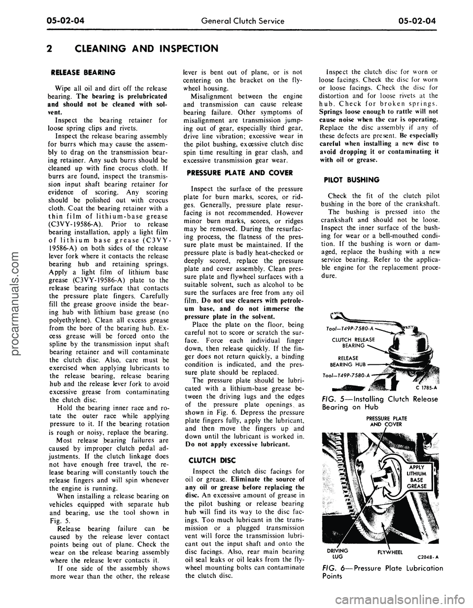
When installing a release bearing on
vehicles equipped with separate hub
and bearing, use the tool shown in
Fig. 5.
Release bearing failure can be
caused by the release lever contact
points being out of plane. Check the
wear on the release bearing assembly
where the release lever contacts it.
If one side of the assembly shows
more wear than the other, the release
lever is bent out of plane, or is not
centering on the bracket on the fly-
wheel housing.
Misalignment between the engine
and transmission can cause release
bearing failure. Other symptoms of
misalignment are transmission jump-
ing out of gear, especially third gear,
drive line vibration; excessive wear in
the pilot bushing, excessive clutch disc
spin time resulting in gear clash, and
excessive transmission gear wear.
PRESSURE PLATE AND COVER
Inspect the surface of the pressure
plate for burn marks, scores, or rid-
ges.
Generally, pressure plate resur-
facing is not recommended. However
minor burn marks, scores, or ridges
may be removed. During the resurfac-
ing process, the flatness of the pres-
sure plate must be maintained. If the
pressure plate is badly heat-checked or
deeply scored, replace the pressure
plate and cover assembly. Clean pres-
sure plate and flywheel surfaces with a
suitable solvent, such as alcohol to be
sure the surfaces are free from any oil
film. Do not use cleaners with petrole-
um base, and do not immerse the
pressure plate in the solvent.
Place the plate on the floor, being
careful not to score or scratch the sur-
face.
Force each individual finger
down, then release quickly. If the fin-
ger does not return quickly, a binding
condition is indicated, and the pres-
sure plate should be replaced.
The pressure plate should be lubri-
cated with a lithium-base grease be-
tween the driving lugs and the edges
of the pressure plate openings, as
shown in Fig. 6. Depress the pressure
plate fingers fully, apply the lubricant,
and then move the fingers up and
down until the lubricant is worked in.
Do not apply excessive lubricant.
CLUTCH DISC
Inspect the clutch disc facings for
oil or grease. Eliminate the source of
any oil or grease before replacing the
disc. An excessive amount of grease in
the pilot bushing or release bearing
hub will find its way to the disc fac-
ings.
Too much lubricant in the trans-
mission or a plugged transmission
vent will force the transmission lubri-
cant out the input shaft and onto the
disc facings. Also, rear main bearing
oil seal leaks or oil leaks from the fly-
wheel mounting bolts can contaminate
the clutch disc.
Inspect the clutch disc for worn or
loose facings. Check the disc for worn
or loose facings. Check the disc for
distortion and for loose rivets at the
hub.
Check for broken springs.
Springs loose enough to rattle will not
cause noise when the car is operating.
Replace the disc assembly if any of
these defects are present. Be especially
careful when installing a new disc to
avoid dropping it or contaminating it
with oil or grease.
PILOT BUSHING
Check the fit of the clutch pilot
bushing in the bore of the crankshaft.
The bushing is pressed into the
crankshaft and should not be loose.
Inspect the inner surface of the bush-
ing for wear or a bell-mouthed condi-
tion. If the bushing is worn or dam-
aged, replace the bushing with a new
service bearing. Refer to the applica-
ble engine for the replacement proce-
dure.
C 1785-A
FIG. 5—Installing Clutch Release
Bearing on Hub
PRESSURE PLATE
AND COVER
DRIVING
LUG
FLYWHEEL
C2048-A
FIG. 6—Pressure Plate Lubrication
Pointsprocarmanuals.com
Page 259 of 413
05-03-01
Clutch
05-03-01
PART 5-3 Clutch
COMPONENT INDEX
CLUTCH EQUALIZER BAR AND/OR
BUSHING
Removal and Installation
CLUTCH PEDAL ASSIST SPRING
Removal and Installation
CLUTCH PEDAL AND/OR BUSHING
Removal and Installation
CLUTCH PEDAL, PEDAL ASSIST SPRING
AND/OR BUSHING
Removal and Installation
CLUTCH PEDAL FREE PLAY ADJUSTMENT
CLUTCH REMOVAL AND INSTALLATION
DESCRIPTION
MODEL APPLICATION
All
Models
Ford
03-05
N/A
N/A
03-03
03-03
03-05
03-01
Mercury
03-05
N/A
N/A
03-03
03-03
03-05
03-01
Meteor
03-05
N/A
N/A
03-03
03-03
03-05
03-01
Cougar
03-05
N/A
N/A
03-04
03-03
03-05
03-01
Fairlane
03-05
03-03
03-04
N/A
03-03
03-05
03-01
Falcon
03-05
03-03
03-04
N/A
03-03
03-05
03-01
Montego
03-05
03-03
03-04
N/A
03-03
03-05
03-01
Mustang
03-05
N/A
N/A
03-04
03-03
03-05
03-01
Lincoln-
Continental
N/A
N/A
N/A
N/A
N/A
N/A
N/A
Thunderbird
N/A
N/A
N/A
N/A
N/A
N/A
N/A
Continental-
Mark
III
N/A
N/A
N/A
N/A
N/A
N/A
N/A
A page number indicates that the item is for the vehicle listed at the head of the column.
N/A indicates that the item is not applicable to the vehicle listed.
DESCRIPTION
DESCRIPTION
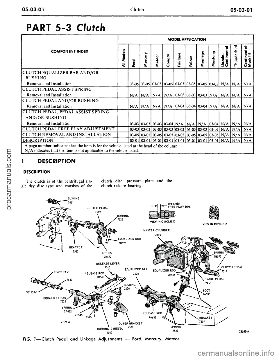
The clutch is of the centrifugal sin-
gle dry disc type and consists of the
clutch disc, pressure plate and the
clutch release bearing.
CLUTCH PEDAL
7519
351538-S
VIEW A
BUSHING-2 REQ'D.
7517
C2055-A
FIG.
1—Clutch
Pedal and Linkage Adjustments —
Ford,
Mercury, Meteor
procarmanuals.com
Page 260 of 413
05-03-02
Clutch
05-03-02
IN-VEHICLE ADJUSTMENTS AND REPAIRS
SPRING-7A600
EQJALIZER ROD-7A516
EQUALIZER BAR-7528
SPRING-7523
FELTWASHER-375475
EQUALIZER
EQUALIZER ROD-7A516
LOCKNUT-34809-S7
RELEASE ROD/
7B543
SNAP RING-7A629
OUTER BRACKET-7507
PIVOT-7A531
RELEASE ROD-7B543
RELEASE ROD-7B543
OUTER EQUALIZER BAR-7528
BUSHING-7526
SPRING-7A632
SNAP RING-7A629
FELT WASHER-375475-S
BUSHING-7543 SPRING-7523
FELT WASHER-358979-S
SPRING-7545
FAIRLANE AND MONTEGO
390 AND 428 ENGINES
FAIRLANE AND MONTEGO
302 AND 351
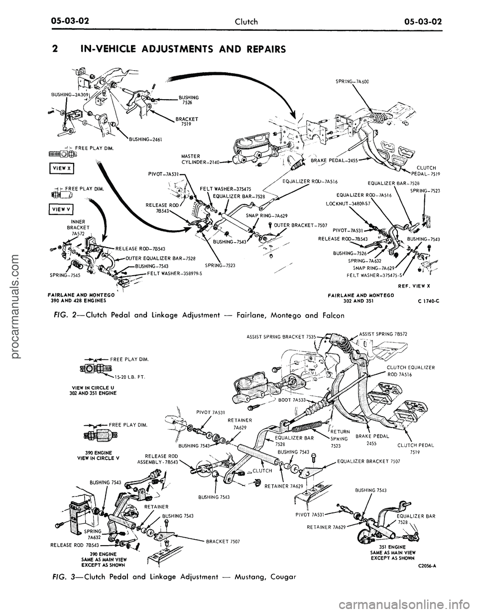
FIG.
2—Clutch
Pedal and Linkage Adjustment — Fairlane, Montego and Falcon
ASSIST SPRING BRACKET 7535-
ASSIST SPRING 7B572
SPRING
7A632
RELEASE ROD 7B543
390 ENGINE
SAME AS MAIN VIEW
EXCEPT AS SHOWN
351 ENGINE
SAME AS MAIN VIEW
EXCEPT AS SHOWN
C2056-A
FIG.
3—Clutch
Pedal and Linkage Adjustment — Mustang, Cougarprocarmanuals.com