FORD MUSTANG 1969 Volume One Chassis
Manufacturer: FORD, Model Year: 1969, Model line: MUSTANG, Model: FORD MUSTANG 1969Pages: 413, PDF Size: 75.81 MB
Page 261 of 413
05-03-03
Clutch
05-03-03
CLUTCH PEDAL
ADJUSTMENTS
Adjust
the
clutch pedal free travel
whenever
the
clutch does
not
disen-
gage properly,
or
when
new
clutch
parts
are
installed. Improper adjust-
ment
of the
clutch pedal
is one of the
most frequent causes
of
clutch failure
and
can be a
contributing factor
in
some transmission failures.
FREE TRAVEL
1.
Disconnect
the
clutch return
spring from
the
release lever.
2.
Loosen
the
release lever
rod
locknut
and
adjusting
nut
(Figs.
1, 2
and
3).
3.
Move
the
clutch release lever
rearward until
the
release bearing
lightly contacts
the
clutch pressure
plate release fingers.
4.
Adjust
the rod
length until
the
rod seats
in the
release lever pocket.
5.
Insert
the
specified feeler gauge
between
the
adjusting
nut and the
swivel sleeve. Then tighten
the
adjust-
ing
nut
against
the
gauge finger tight.
6. Tighten
the
locknut against
the
adjusting
nut,
being careful
not to di-
sturb
the
adjustment. Torque
the
lock-
nut
to
specification
and
remove
the
feeler gauge.
7.
Install
the
clutch return spring.
8. Check
the
free travel
at the
pedal
for conformance
to
specification.
Re-
adjust
if
necessary.
9.
As a
final check, measure
the
pedal free travel with
the
transmission
in neutral
and the
engine running
at
about 3000
rpm. If the
pedal free
travel
at
this speed
is not a
minimum
of
1/2
inch, readjust
the
clutch pedal
free travel. Otherwise,
the
release
fin-
gers
may
contact
the
release bearing
continuously, resulting
in
premature
bearing
and
clutch failure. Free travel
must
be
exactly
to
specification.
CLUTCH ASSIST
SPRING REPLACEMENT
(FAIRLANE, FALCON,
MONTEGO)
1.
Remove
the
cotter
pin
from
the
clutch
rod at the
clutch pedal lever
as-
sembly inside
the
passenger compart-
ment.
2.
Grasp
the
clutch pedal lever
firmly
to
prevent slipping
and
remove
the clutch
rod
from
the
lever. Allow
the clutch pedal lever
to
rest
on the
floor panel.
3.
Remove
the
forward bolt secur-
ing
the
assist spring bracket
to the
brake pedal bracket
and
loosen
the
rear bolt
two or
three turns.
Do not
remove
the
rear bolt.
4.
Grasp
the
assist spring bracket
with pliers
and
rotate upward until
the
spring
can be
separated from
the
bracket.
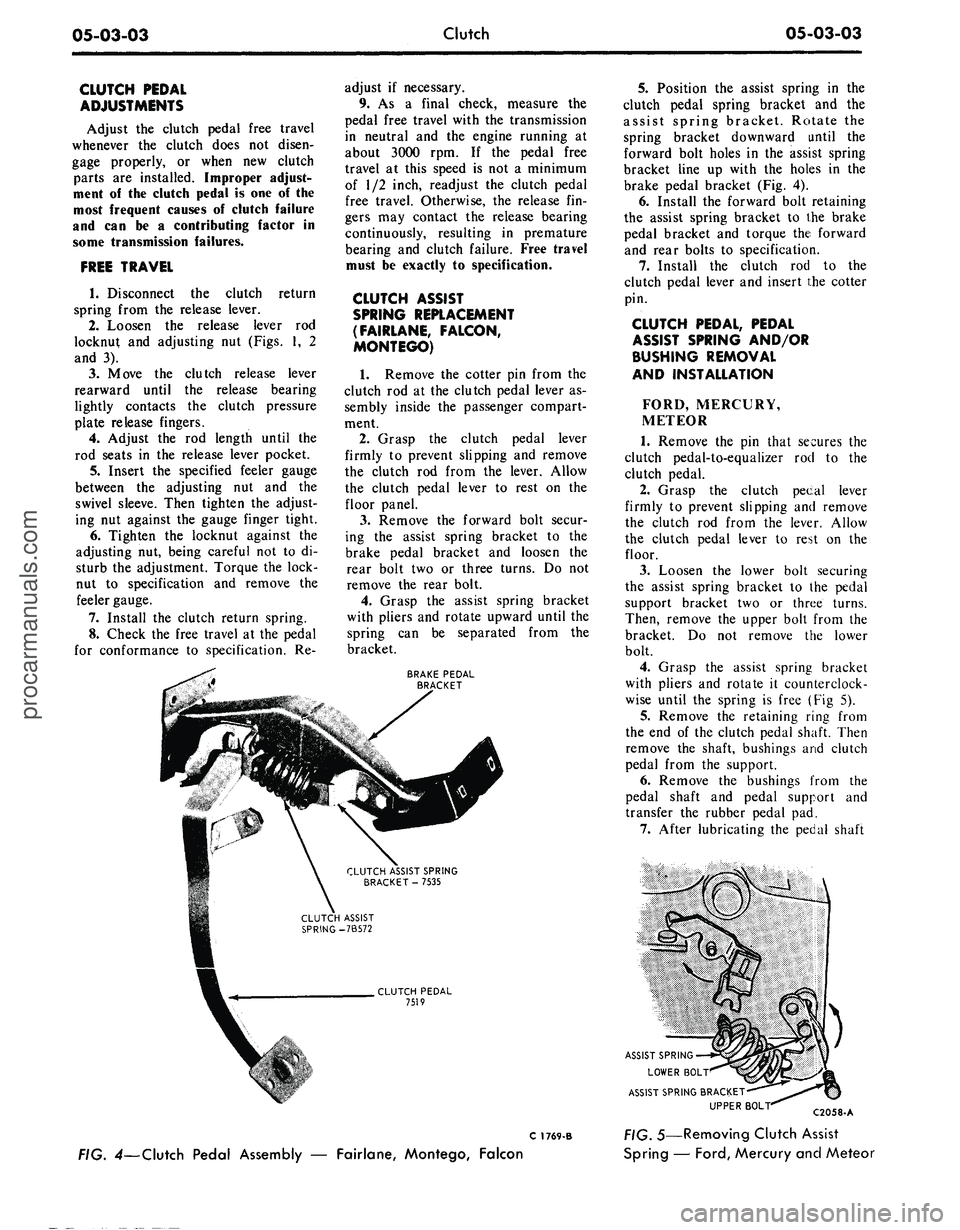
BRAKE PEDAL
BRACKET
CLUTCH ASSIST SPRING
BRACKET
-
7535
CLUTCH PEDAL
7519
5.
Position
the
assist spring
in the
clutch pedal spring bracket
and the
assist spring bracket. Rotate
the
spring bracket downward until
the
forward bolt holes
in the
assist spring
bracket line
up
with
the
holes
in the
brake pedal bracket
(Fig. 4).
6. Install
the
forward bolt retaining
the assist spring bracket
to the
brake
pedal bracket
and
torque
the
forward
and rear bolts
to
specification.
7.
Install
the
clutch
rod to the
clutch pedal lever
and
insert
the
cotter
pin.
CLUTCH PEDAL, PEDAL
ASSIST SPRING AND/OR
BUSHING REMOVAL
AND INSTALLATION
FORD, MERCURY,
METEOR
1.
Remove
the pin
that secures
the
clutch pedal-to-equalizer
rod to the
clutch pedal.
2.
Grasp
the
clutch pecal lever
firmly
to
prevent slipping
and
remove
the clutch
rod
from
the
lever. Allow
the clutch pedal lever
to
rest
on the
floor.
3.
Loosen
the
lower bolt securing
the assist spring bracket
to the
pedal
support bracket
two or
three turns.
Then, remove
the
upper bolt from
the
bracket.
Do not
remove
the
lower
bolt.
4.
Grasp
the
assist spring bracket
with pliers
and
rotate
it
counterclock-
wise until
the
spring
is
free
(Fig 5).
5.
Remove
the
retaining ring from
the
end of the
clutch pedal shaft. Then
remove
the
shaft, bushings
and
clutch
pedal from
the
support.
6. Remove
the
bushings from
the
pedal shaft
and
pedal support
and
transfer
the
rubber pedal
pad.
7.
After lubricating
the
pedal shaft
ASSIST SPRING
LOWER BOLT
ASSIST SPRING BRACKET-
UPPER
BOL"
C 1769-B
FIG. 4—Clutch Pedal Assembly
—
Fairlane, Montego, Falcon
C2058-A
;. 5—Removing Clutch Assist
Spring
—
Ford,
Mercury and Meteorprocarmanuals.com
Page 262 of 413
05-03-04
Clutch
05-03-04
bushings, position the clutch pedal and
bushings in the pedal support.
8. Install the retaining ring on the
clutch pedal shaft.
9. Position the assist spring in the
pedal support bracket and the assist
spring bracket. Rotate the assist
spring bracket clockwise until the
upper bolt holes line up and install the
bolt. Torque both the upper and lower
bolts to specification.
10.
Check the clutch pedal free
travel and adjust as required.
MUSTANG, COUGAR
1.
Disconnect the battery ground
cable.
2.
Remove the steering column.
Refer to Group 3 of this manual for
the procedure.
3.
Remove the two capscrews re-
taining the master cylinder or booster
to the dash panel. Then remove the
two capscrews retaining the pedal sup-
port bracket to the dash panel.
4.
Working inside the vehicle, dis-
connect the clutch pedal-to-equalizer
rod at the clutch pedal by removing
the retainer and bushing.
5.
Secure the clutch pedal against
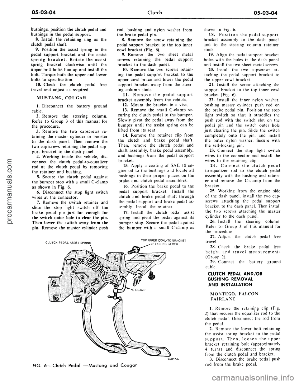
the bumper stop with a small C-clamp
as shown in Fig. 6.
6. Disconnect the stop light switch
wires at the connector.
7.
Remove the switch retainer and
slide the stop light switch off the
brake pedal pin just far enough for
the switch outer hole to clear the pin.
Then lower the switch away from the
pin.
Remove the master cylinder push
CLUTCH PEDAL ASSIST SPRING
rod, bushing and nylon washer from
the brake pedal pin.
8. Remove the screw retaining the
pedal support bracket to the top inner
cowl bracket (Fig. 6).
9. Remove the two sheet metal
screws retaining the pedal support
bracket to the dash panel.
10.
Remove the two screws retain-
ing the pedal support bracket to the
upper cowl brace and lower the pedal
support bracket away from the steer-
ing column studs.
11.
Remove the pedal support
bracket assembly from the vehicle.
12.
Mount the bracket in a vise.
13.
Remove the small C-clamp se-
curing the clutch pedal to the bumper.
Slowly pivot the pedal away from the
bumper until the assist spring can be
lifted from its seat.
14.
Remove the retainer clip from
the clutch and brake pedal shaft.
Then, remove the clutch pedal and
shaft assembly, brake pedal assembly,
and bushings from the pedal support
bracket.
15.
Apply a coating of SAE 10 en-
gine oil to the bushings and locate all
bushings in their proper places on the
brake and clutch pedal assemblies.
16.
Position the brake pedal to the
pedal support bracket. Install the
clutch and brake pedal shaft through
the pedal support and brake pedal as-
sembly. Install the retainer.
17.
Install the clutch pedal assist
spring and pivot the pedal against its
bumper stop. Secure the pedal against
the bumper with a small C-clamp as
TOP INNER COWL-TO-BRACKET
RETAINING SCREW
C2057-A
FIG.
6—Clutch
Pedal —Mustang and Couga?
shown in Fig. 6.
18.
Position the pedal support
bracket assembly to the dash panel
and to the steering column retainer
studs.
19.
Align the pedal support bracket
holes with the holes in the dash panel
and install the two sheet metal screws.
20.
Install the two capscrews at-
taching the pedal support bracket to
the upper cowl bracket.
21.
Install the screw attaching the
support bracket to the top inner cowl
bracket (Fig. 6).
22.
Install the inner nylon washer,
bushing master cylinder push rod on
the brake pedal pin. Position the stop
light switch so that it straddles the
push rod with the switch slot on the
pedal pin and the switch outer hole
just clearing the pin. Slide the switch
completely onto the pin, and install
the outer nylon washer. Secure with
the self-locking pin.
23.
Connect the stop light switch
wires to the connector and install the
wires to the retaining clip.
24.
Connect the clutch pedal-
to-equalizer rod to the clutch pedal
assembly with the bushing and retain-
er and remove the C-clamp from the
bracket.
25.
Working from the engine side
of the dash panel, install the two cap-
screws attaching the pedal support
bracket to the dash panel. Then install
the two screws attaching the master
cylinder to the dash panel.
26.
Install the steering column.
Refer to Group 3 of this manual for
the procedure.
27.
Adjust the clutch pedal free
travel.
28.
Check the brake pedal free
height and travel measurements
(Group 2).
29.
Connect the battery ground
cable.
CLUTCH PEDAL AND/OR
BUSHING REMOVAL
AND INSTALLATION
MOM EGO, FALCON
FAIRLANF
1.
Remove the retaining clip (Fig.
2) that secures the equalizer rod to the
clutch pedal. Disconnect the rod from
the pedal.
2.
Remove the lower bolt retaining
the assist spring bracket to the pedal
support. Then, loosen the upper
bracket retaining bolt (approximately
4 turns) and disconnect the spring
from the clutch pedal and bracket.
3.
Disconnect the brake pedal push
rod from the brake pedal.procarmanuals.com
Page 263 of 413
05-03-05
Clutch
05-03-05
4.
Remove the bolt that secures the
left air vent control cable bracket to
the instrument panel. Position the
control cable to one side.
5.
Remove the retaining clip and
flat washer from the clutch pedal
shaft. Then, remove the shaft, bush-
ing, clutch pedal and brake pedal
from the support.
6. Remove the bushings from the
pedal shaft, and transfer the pedal
pad.
7.
Lubricate the clutch pedal shaft
bushings and position them on the
shaft. Then, position the brake pedal
and clutch pedal in the pedal support.
8. Install the flat washer and re-
taining clip on the pedal shaft.
9. Position the assist spring to the
pedal and bracket. Pry the bracket
forward and install the lower bolt.
Torque the bolts to specifications.
10.
Position the master cylinder
push rod, bushing, and washers on the
brake pedal and secure with a retain-
ing clip.
11.
Connect the equalizer rod to
the clutch pedal and secure it in place
with a retaining clip.
12.
Position the air vent control
cable bracket to the instrument panel
and secure with the attaching bolt.
13.
Adjust the clutch pedal free
travel.
EQUALIZER BAR AND/OR
BUSHING REMOVAL AND
INSTALLATION
FORD, MERCURY
AND METEOR
1.
Raise the vehicle and disconnect
the clutch pedal-to-equalizer rod at
the equalizer bar (Fig. 1).
2.
Disconnect the return spring and
retaining spring at the release lever.
Separate the release lever rod from
the release lever.
3.
Remove the equalizer bar frame
bracket from the frame.
4.
Remove the equalizer bar from
the pivot on the flywheel housing.
5.
Remove the wire clip to replace
the outer bushing and the snap ring
from the inner pivot stud to replace
the inner bushing.
6. Position the flat washer, felt
washer and bushing on the inner and
outer pivots. Secure these parts with
the snap ring.
7.
Position the equalizer bar on the
inner pivot and bolt the equalizer bar
frame bracket to the frame. Torque
the attaching bolts to specification.
8. Install the clutch release rod, re-
turn spring and retaining spring.
9. Connect the clutch pedal rod to
the equalizer bar.
10.
Adjust the clutch pedal free
travel.
MUSTANG, COUGAR,
MONTEGO, FALCON,
FAIRLANE (EXCEPT
MONTEGO AND FAIRLANE
WITH 390 V-8)
1.
Disconnect the clutch pedal
equalizer rod at the equalizer bar
(Figs.
2 and 3).
2.
Raise the vehicle and disconnect
the release lever, return spring at the
lever.
3.
Remove the equalizer bar outer
bracket and bushing assembly.
4.
Remove the release rod from the
equalizer bar, and then remove the
equalizer bar. Remove the bushing
and washers from the inner mounting
stud.
5.
Position the equalizer bar, wash-
ers,
inner bushing, and retainer on the
inner stud.
6. After positioning the outer bush-
ing, install the outer bracket (with the
equalizer bar in place).
7.
Connect the release rod and the
release lever return spring.
8. Lower the vehicle. Connect the
clutch pedal equalizer rod to the
equalizer baY and secure with the re-
taining pin.
9. Adjust the clutch pedal free trav-
el as required.
MONTEGO AND
FAIRLANE—390 V-8
1.
Disconnect the clutch pedal
equalizer rod at the equalizer bar (Fig.
2).
2.
Raise the vehicle and disconnect
the return spring at the release lever.
Disconnect the release lever rod from
the equalizer lever.
3.
Remove the equalizer bar center
bolt.
4.
Separate the equalizer bar and
remove both sections from the vehicle.
5.
Remove the bolts retaining the
equalizer bar inner bracket to the fly-
wheel housing and remove the bracket
and bushing assembly.
6. Remove the equalizer bar outer
bracket and bushing assembly.
7.
Remove the snap ring, bushing,
and felt washer from each bracket as-
sembly.
8. Position a felt washer, and bush-
ing on each bracket assembly and se-
cure with the snap ring.
9. Install the outer bracket and
bushing assembly to the frame (Fig.
2).
Torque the bracket attaching bolts
to specifications.
10.
Position the outer section of the
equalizer bar on the outer bracket
pivot.
11.
Connect the two sections of the
equalizer bar. Insert the inner bracket
pivot into the equalizer bar and install
the assembly to the flywheel housing.
Torque the attaching bolts to specifi-
cations.
12.
Install the equalizer bar center
bolt and torque to specifications.
Make sure that both ends of the
equalizer bar are against the felt
washers.
13.
Connect the release rod and the
release lever return spring.
14.
Adjust the clutch pedal free
travel.
15.
Lower the vehicle. Connect the
clutch pedal equalizer rod to the
equalizer bar and secure with the re-
taining clip.
16.
Check the free travel at the
pedal for conformance to specifica-
tions.
Readjust if necessary.
REMOVAL AND INSTALLATION
CLUTCH REMOVAL
1.
Raise the vehicle on a hoist.
2.
Disconnect the drive shaft from
the rear U-joint flange. Then, slide the
drive shaft off the transmission output
shaft. Insert the appropriate tool over
the output shaft and into the extension
housing oil seal.
3.
Disconnect the speedometer
cable from the extension housing.
4.
Disconnect the gear shift rods
from the transmission. If the vehicle is
equipped with a four-speed transmis-
sion, remove the bolts that secure the
four-speed transmission, disconnect
the front brake cable from the cross-
member and remove the crossmem-
member from the vehicle.
5.
Remove the bolts that attach the
transmission to the flywheel housing.
6. Move the transmission rearward
until the input shaft clears the fly-
wheel housing, then remove it from
the vehicle.
7.
Disconnect the clutch release
lever retaining spring from the release
lever.procarmanuals.com
Page 264 of 413
05-03-06
Clutch
05-03-06
8. Remove the starter cable then
remove the starter motor from the fly-
wheel housing.
9. Remove the bolts that secure the
engine rear plate to the front lower
part of the flywheel housing.
10.
Remove the flywheel housing
lower cover (390 CID housing only).
11.
Remove the bolts that attach
the housing to the cylinder block.
12.
Move the housing back just far
enough to clear the pressure plate,
then move it to the right to free the
pivot from the clutch equalizer bar. Be
careful not to disturb the linkage and
assist spring.
13.
Loosen the six pressure plate
cover attaching bolts evenly to release
the spring tension. If the same pres-
sure plate and cover is to be installed
after the clutch is overhauled, mark
the cover and flywheel so that the
pressure plate can be installed in the
same position.
14.
Remove the pressure plate and
the clutch disc from the flywheel.
CLUTCH INSTALLATION
1.
Install the clutch release lever if
it was removed.
2.
Place the clutch disc, and pres-
sure plate assembly in position on the
flywheel. Start the cover attaching
bolts to hold the pieces in place, but
do not tighten them. Avoid touching
the clutch disc facing, dropping the
parts or contaminating them with oil
or grease as clutch chatter may result.
3.
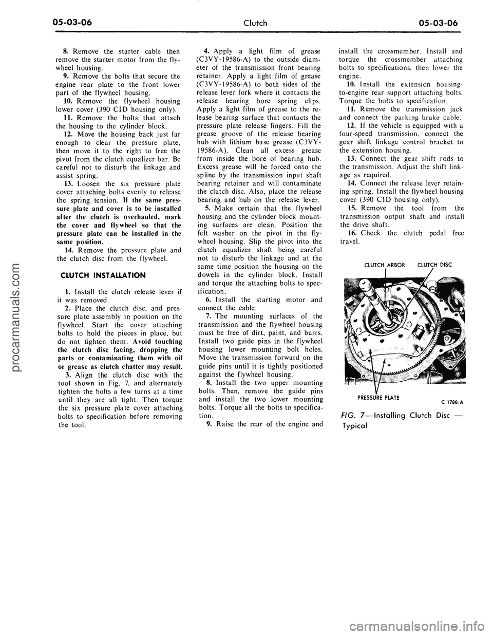
Align the clutch disc with the
tool shown in Fig. 7, and alternately
tighten the bolts a few turns at a time
until they are all tight. Then torque
the six pressure plate cover attaching
bolts to specification before removing
the tool.
4.
Apply a light film of grease
(C3VY-19586-A) to the outside diam-
eter of the transmission front bearing
retainer. Apply a light film of grease
(C3VY-19586-A) to both sides of the
release lever fork where it contacts the
release bearing bore spring clips.
Apply a light film of grease to the re-
lease bearing surface that contacts the
pressure plate release fingers. Fill the
grease groove of the release bearing
hub with lithium base grease (C3VY-
19586-A). Clean all excess grease
from inside the bore of bearing hub.
Excess grease will be forced onto the
spline by the transmission input shaft
bearing retainer and will contaminate
the clutch disc. Also, place the release
bearing and hub on the release lever.
5.
Make certain that the flywheel
housing and the cylinder block mount-
ing surfaces are clean. Position the
felt washer on the pivot in the fly-
wheel housing. Slip the pivot into the
clutch equalizer shaft being careful
not to disturb the linkage and at the
same time position the housing on the
dowels in the cylinder block. Install
and torque the attaching bolts to spec-
ification.
6. Install the starting motor and
connect the cable.
7.
The mounting surfaces of the
transmission and the flywheel housing
must be free of dirt, paint, and burrs.
Install two guide pins in the flywheel
housing lower mounting bolt holes.
Move the transmission forward on the
guide pins until it is tightly positioned
against the flywheel housing.
8. Install the two upper mounting
bolts.
Then, remove the guide pins
and install the two lower mounting
bolts.
Torque all the bolts to specifica-
tion.
9. Raise the rear of the engine and
install the crossmember. Install and
torque the crossmember attaching
bolts to specifications, then lower the
engine.
10.
Install the extension housing-
to-engine rear support attaching bolts.
Torque the bolts to specification.
11.
Remove the transmission jack
and connect the parking brake cable.
12.
If the vehicle is equipped with a
four-speed transmission, connect the
gear shift linkage control bracket to
the extension housing.
13.
Connect the gear shift rods to
the transmission. Adjust the shift link-
age as required.
14.
Connect the release lever retain-
ing spring. Install the flywheel housing
cover (390 CID housing only).
15.
Remove the tool from the
transmission output shaft and install
the drive shaft.
16.
Check the clutch pedal free
travel.
CLUTCH ARBOR CLUTCH DISC
PRESSURE PLATE
C 1788-A
FIG. 7—Installing Clutch Disc —
Typicalprocarmanuals.com
Page 265 of 413
05-04-01
Specifications
05-04-01
PART
5-4
Specifications
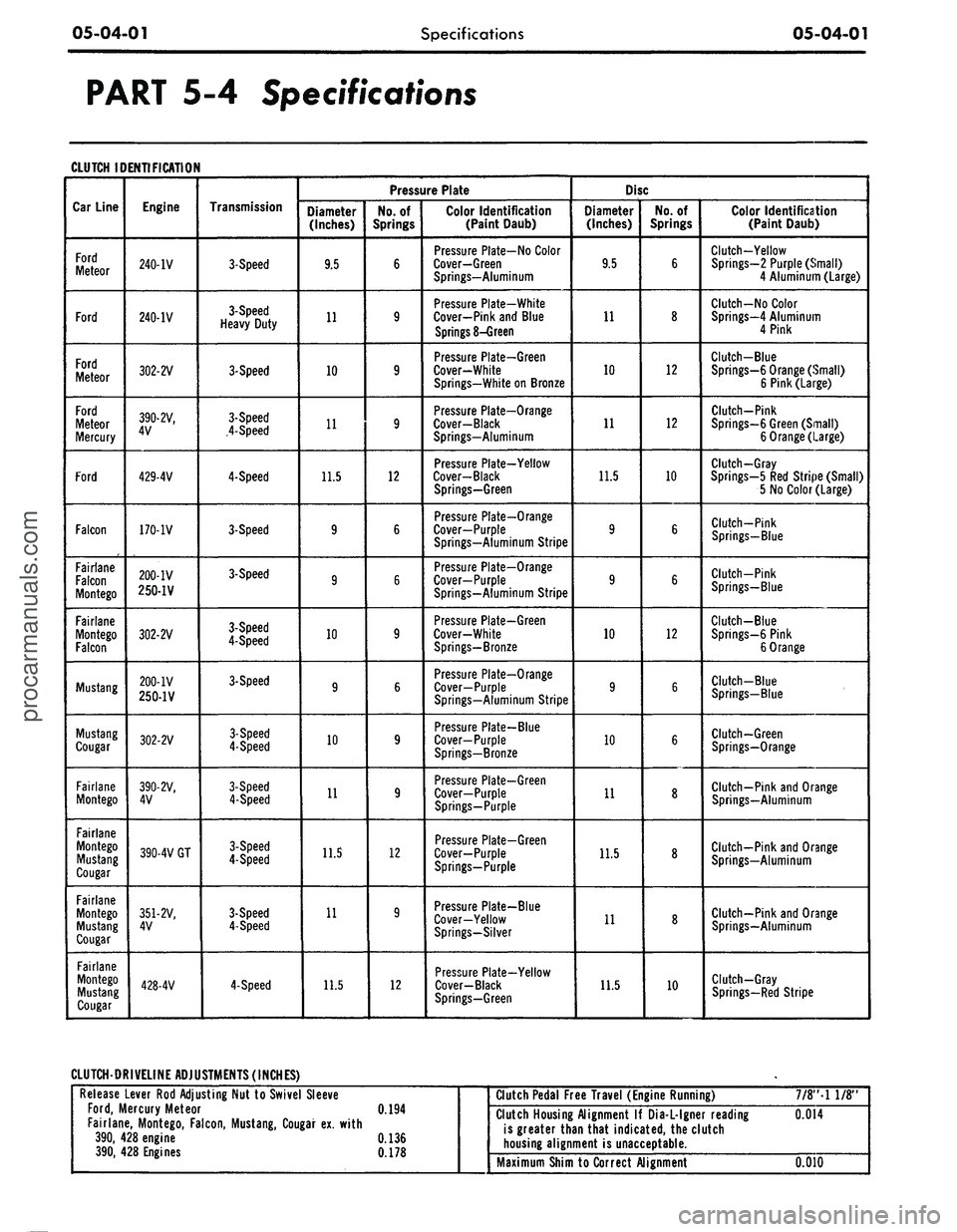
CLUTCH IDENTIFICATION
Car Line
Ford
Meteor
Ford
Ford
Meteor
Ford
Meteor
Mercury
Ford
Falcon
Fairlane
Falcon
Montego
Fairlane
Montego
Falcon
Mustang
Mustang
Cougar
Fairlane
Montego
Fairlane
Montego
Mustang
Cougar
Fairlane
Montego
Mustang
Cougar
Fairlane
Montego
Mustang
Cougar
Engine
240-IV
240-IV
302-2V
390-2V,
4V
429-4V
170-1V
200-IV
250-1V
302-2V
200-IV
250-1V
302-2V
390-2V,
4V
390-4V GT
351-2V,
4V
428-4V
Transmission
3-Speed
3-Speed
Heavy Duty
3-Speed
3-Speed
4-Speed
4-Speed
3-Speed
3-Speed
3-Speed
4-Speed
3-Speed
3-Speed
4-Speed
3-Speed
4-Speed
3-Speed
4-Speed
3-Speed
4-Speed
4-Speed
Pressure Plate
Diameter
(Inches)
9.5
11
10
11
11.5
9
9
10
9
10
11
11.5
11
11.5
No.
of
Springs
6
9
9
9
12
6
6
9
6
9
9
12
9
12
Color Identification
(Paint Daub)
Pressure Plate-No Color
Cover—Green
Springs—Aluminum
Pressure Plate-White
Cover-Pink and Blue
Springs
8-Green
Pressure Plate-Green
Cover-White
Springs-White
on
Bronze
Pressure Plate—Orange
Cover-Black
Springs-Aluminum
Pressure Plate-Yellow
Cover-Black
Springs-Green
Pressure Plate-Orange
Cover—Purple
Springs-Aluminum Stripe
Pressure Plate-Orange
Cover-Purple
Springs-Aluminum Stripe
Pressure Plate—Green
Cover-White
Springs-Bronze
Pressure Plate—Orange
Cover—Purple
Springs—Aluminum Stripe
Pressure Plate-Blue
Cover—Purple
Springs—Bronze
Pressure Plate-Green
Cover-Purple
Springs-Purple
Pressure Plate-Green
Cover-Purple
Springs-Purple
Pressure Plate-Blue
Cover-Yellow
Springs-Silver
Pressure Plate-Yellow
Cover-Black
Springs—Green
Disc
Diameter
(Inches)
9.5
11
10
11
11.5
9
9
10
9
10
11
11.5
11
11.5
No.
of
Springs
6
8
12
12
10
6
6
12
6
6
8
8
8
10
Color Identification
(Paint Daub)
Clutch-Yellow
Springs—2 Purple (Small)
4 Aluminum (Large)
Clutch-No Color
Springs—4 Aluminum
4 Pink
Clutch-Blue
Springs-6 Orange (Small)
6 Pink (Large)
Clutch-Pink
Springs-6 Green (Small)
6 Orange (Large)
Clutch-Gray
Springs—5
Red
Stripe (Small)
5
No
Color (Large)
Clutch-Pink
Springs—Blue
Clutch-Pink
Springs-Blue
Clutch-Blue
Springs-6 Pink
6 Orange
Clutch-Blue
Springs—Blue
Clutch-Green
Springs-Orange
Clutch-Pink
and
Orange
Springs—Aluminum
Clutch-Pink and Orange
Springs—Aluminum
Clutch—Pink and Orange
Springs—Aluminum
Clutch-Gray
Springs-Red Stripe
CLUTCH-DRIVELINE ADJUSTMENTS (INCHES)
Release Lever
Rod
Adjusting
Nut to
Swivel Sleeve
Ford,
Mercury Meteor
0.194
Fairlane, Montego, Falcon, Mustang, Cougar
ex.
with
390,
428
engine
0.136
390,
428
Engines
0.178
*
Clutch Pedal Free Travel (Engine Running)
7/8"-l
1/8"
Clutch Housing Alignment
If
Dia-L-lgner reading
0.014
is greater than that indicated,
the
clutch
housing alignment
is
unacceptable.
Maximum Shim to Correct Alignment
0.010procarmanuals.com
Page 266 of 413
05-04-02
Specifications
05-04-02
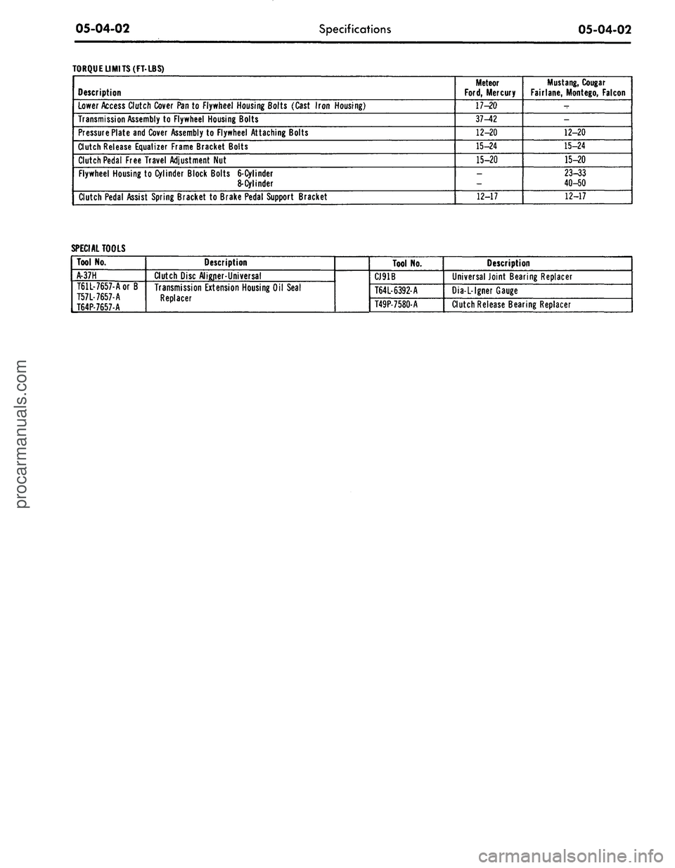
TORQUE LIMITS (FT-LBS)
Description
Lower Access Clutch Cover Pan to Flywheel Housing Bolts (Cast Iron Housing)
Transmission Assembly to Flywheel Housing Bolts
Pressure Plate and Cover Assembly to Flywheel Attaching Bolts
Clutch Release Equalizer Frame Bracket Bolts
Clutch Pedal Free Travel Adjustment Nut
Flywheel Housing to Cylinder Block Bolts
6-Cylinder
8-Cylinder
Clutch Pedal Assist Spring Bracket to Brake Pedal Support Bracket
Meteor
Ford,
Mercury
17-20
37-42
12-20
15-24
15-20
_
12-17
Mustang,
Cougar
Fairlane, Montego, Falcon
-
-
12-20
15-24
15-20
23-33
40-50
12-17
SPECIAL TOOLS
Tool No.
A-37H
T61L-7657-Aor B
T57L-7657-A
T64P-7657-A
Description
Clutch Disc Aligner-Universal
Transmission Extension Housing Oil Seal
Replacer
Tool No.
CJ91B
T64L-6392-A
T49P-7580-A
Description
Universal Joint Bearing Replacer
Dia-L-lgner Gauge
Clutch Release Bearing Replacerprocarmanuals.com
Page 267 of 413
06-01-01
06-01-01
ual Shift
GROUP
6
PART
6-1
PAGE
General Transmission Service
06-01-01
PART 6-2
Ford Design Three-Speed
Transmission
06-02-01
PART 6-3
Ford Design Four-Speed
Transmission
PART
6-4
Specifications
PAGE
.06-03-01
.06-04-01
Part 6-1 General
Transmission
Service
COMPONENT INDEX
REAR SEAL
Removal and Installation
REAR BUSHING AND SEAL
Removal and Installation
TRANSMISSION
Cleaning
Inspection
Lubrication
MODEL APPLICATION
All
Models
Ford
01-02
01-02
01-02
01-02
01-02
Mercury
01-02
01-02
01-02
01-02
01-02
Meteor
01-02
01-02
01-02
01-02
01-02
Cougar
01-02
01-02
01-02
01-02
01-02
Fairlane
01-02
01-02
01-02
01-02
01-02
Falcon
01-02
01-02
01-02
01-02
01-02
Montego
01-02
01-02
01-02
01-02
01-02
Mustang
01-02
01-02
01-02
01-02
01-02
Lincoln-
Continental
N/A
N/A
N/A
N/A
N/A
Thunderbird
N/A
N/A
N/A
N/A
N/A
Continental-
Mark
III
N/A
N/A
N/A
N/A
N/A
A page number indicates that the item
is for
the vehicle listed
at
the head
of
the column.
N/A indicates that the item
is
not applicable
to
the vehicle listed.
COMMON ADJUSTMENTS
AND
REPAIRS
54E
M IB I2H 33
CODE
1
5
6
TRANSMISSION
THREE-SPEED
FOUR-SPEED (WIDE RATIO)
FOUR-SPEED (CLOSE RATIO)
C2086-A
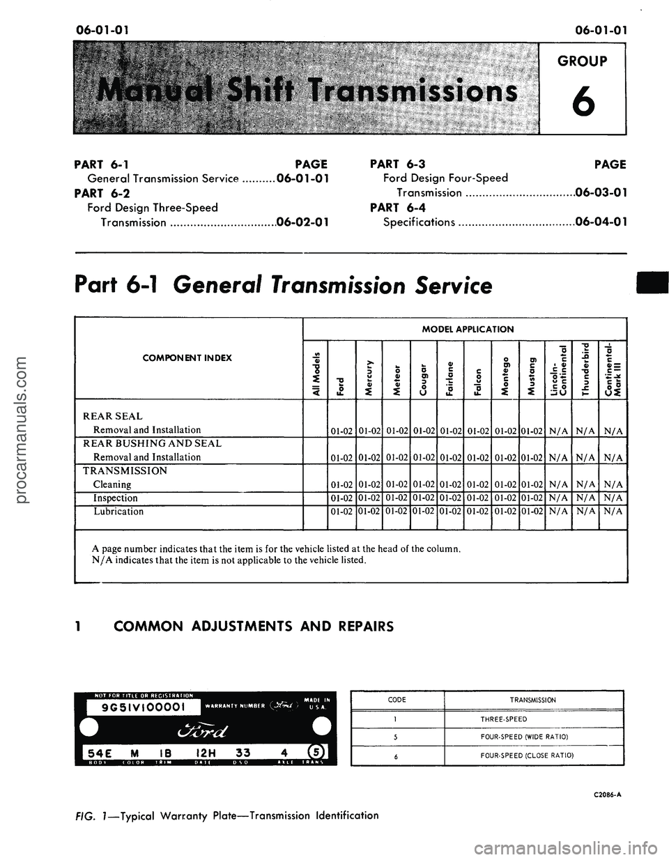
FIG.
1—Typical
Warranty Plate—Transmission Identification
procarmanuals.com
Page 268 of 413
06-01-02
General Transmission Service
06-01-02
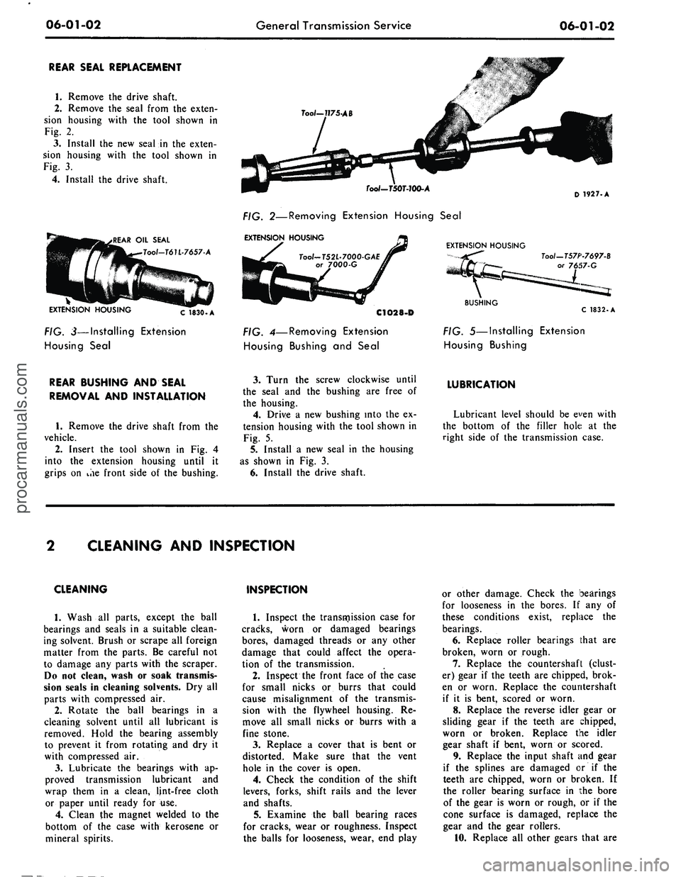
REAR SEAL REPLACEMENT
1.
Remove the drive shaft.
2.
Remove the seal from the exten-
sion housing with the tool shown in
Fig. 2.
3.
Install the new seal in the exten-
sion housing with the tool shown in
Fig. 3.
4.
Install the drive shaft.
.REAR OIL SEAL
Tool-T61L-7657-A
EXTENSION HOUSING
C 1830.A
FIG. 3—Installing Extension
Housing Seal
Too/-7J75-AB
Tool-TSOT-lOO-A
FIG. 2—Removing Extension Housing Seal
EXTENSION HOUSING
Tool-T52L-7000-GAE
or 7000-G
C1O28-D
FIG. 4—Removing Extension
Housing Bushing and Seal
EXTENSION HOUSING
D
1927. A
Tool—T57P-7697-B
57-G
BUSHING
C 1832.A
FIG. 5—Installing Extension
Housing Bushing
REAR BUSHING AND SEAL
REMOVAL AND INSTALLATION
1.
Remove the drive shaft from the
vehicle.
2.
Insert the tool shown in Fig. 4
into the extension housing until it
grips on ihe front side of the bushing.
3.
Turn the screw clockwise until
the seal and the bushing are free of
the housing.
4.
Drive a new bushing into the ex-
tension housing with the tool shown in
Fig. 5.
5.
Install a new seal in the housing
as shown in Fig. 3.
6. Install the drive shaft.
LUBRICATION
Lubricant level should be even with
the bottom of the filler hole at the
right side of the transmission case.
CLEANING AND INSPECTION
CLEANING
1.
Wash all parts, except the ball
bearings and seals in a suitable clean-
ing solvent. Brush or scrape all foreign
matter from the parts. Be careful not
to damage any parts with the scraper.
Do not clean, wash or soak transmis-
sion seals in cleaning solvents. Dry all
parts with compressed air.
2.
Rotate the ball bearings in a
cleaning solvent until all lubricant is
removed. Hold the bearing assembly
to prevent it from rotating and dry it
with compressed air.
3.
Lubricate the bearings with ap-
proved transmission lubricant and
wrap them in a clean, lint-free cloth
or paper until ready for use.
4.
Clean the magnet welded to the
bottom of the case with kerosene or
mineral spirits.
INSPECTION
1.
Inspect the transmission case for
cracks, worn or damaged bearings
bores,
damaged threads or any other
damage that could affect the opera-
tion of the transmission.
2.
Inspect the front face of the case
for small nicks or burrs that could
cause misalignment of the transmis-
sion with the flywheel housing. Re-
move all small nicks or burrs with a
fine stone.
3.
Replace a cover that is bent or
distorted. Make sure that the vent
hole in the cover is open.
4.
Check the condition of the shift
levers, forks, shift rails and the lever
and shafts.
5.
Examine the ball bearing races
for cracks, wear or roughness. Inspect
the balls for looseness, wear, end play
or other damage. Check the bearings
for looseness in the bores. If any of
these conditions exist, replace the
bearings.
6. Replace roller bearings that are
broken, worn or rough.
7.
Replace the countershaft (clust-
er) gear if the teeth are chipped, brok-
en or worn. Replace the countershaft
if it is bent, scored or worn.
8. Replace the reverse idler gear or
sliding gear if the teeth are chipped,
worn or broken. Replace the idler
gear shaft if bent, worn or scored.
9. Replace the input shaft and gear
if the splines are damaged or if the
teeth are chipped, worn or broken. If
the roller bearing surface in the bore
of the gear is worn or rough, or if the
cone surface is damaged, replace the
gear and the gear rollers.
10.
Replace all other gears that areprocarmanuals.com
Page 269 of 413
06-01-03
General Transmission Service
06-01-03
chipped, broken or worn.
11.
Check the synchronizer sleeves
for free movement on their hubs.
Make sure that the alignment marks
(etched marks) are properly indexed.
12.
Inspect the synchronizer block-
ing rings for widened index slots,
rounded clutch teeth and smooth in-
ternal surfaces (must have machined
grooves). With the blocker ring on the
cone,
the distance between the face of
the blocker ring and the clutch teeth
on the gear must not be less than
0.010 inches.
13.
Replace the speedometer drive
gear if the teeth are stripped or dam-
aged. Make certain to install the cor-
rect size replacement gear.
14.
Replace the output shaft if
there is any evidence of wear or if any
of the splines are damaged.
15.
Inspect the bushing and the seal
in the extension housing. Replace
them if they are worn or damaged.
The bushing and/or seal should be re-
placed after the extension housing has
been installed on the transmission.
16.
Replace the seal in the input
shaft bearing retainer.
17.
Replace the seals on the cam
and shafts.procarmanuals.com
Page 270 of 413
06-02-01
Ford Design Three Speed Transmission
06-02-01
PART 6-2 Ford Design Three Speed
Transmission
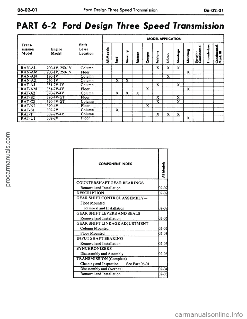
Trans-
mission
Model
RAN-AL
RAN-AM
RAN-AN
RAN-AZ
RAT-AJ
RAT-AM
RAT-A2
RAT-B2
RAT-C2
RAT-N2
RAT-SI
RAT-T
RAT-U1
Engine
Model
200-IV, 250-IV
200-IV, 250-IV
170-1V
240-IV
351-2V-4V
351-2V-4V
390-2V-4V
390-4V-GT
390-4V-GT
390-4V
302-2V
302-2V-4V
302-2V
Shift
Lever
Location
Column
Floor
Column
Column
Column
Floor
Column
Floor
Column
Floor
Column
Column
Floor
MODEL APPLICATION
All
Models
Ford
X
X
X
Mercury
X
X
Meteor
X
Cougar
X
X
Fairiane
X
X
X
X
X
Falcon
X
X
X
Montego
X
X
X
X
X
Mustang
X
X
X
Lincoln-
Continental
Thunderbird
Continental-
Mark
III
COMPONENT INDEX
COUNTERSHAFT GEAR BEARINGS
Removal and Installation
DESCRIPTION
GEAR SHIFT CONTROL ASSEMBLY—
Floor Mounted
Removal and Installation
GEAR SHIFT LEVERS AND SEALS
Removal and Installation
GEAR SHIFT LINKAGE ADJUSTMENT
Column Mounted
Floor Mounted
INPUT SHAFT BEARING
Removal and Installation
SYNCHRONIZERS
Disassembly and Assembly
TRANSMISSION (Complete)
Cleaning and Inspection See Part 06-01
Disassembly and Overhaul
Removal and Installation
AH
Models
02-07
02-02
02-07
02-06
02-02
02-03
02-06
02-06
02-04
02-03
procarmanuals.com