GEELY CK 2008 Workshop Manual
Manufacturer: GEELY, Model Year: 2008, Model line: CK, Model: GEELY CK 2008Pages: 392, PDF Size: 38.86 MB
Page 161 of 392
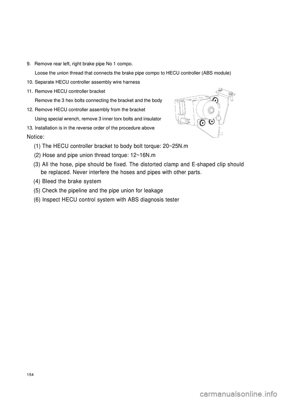
1549. Remove rear left, right brake pipe No 1 compo.
Loose the union thread that connects the brake pipe compo to HECU controller (ABS module)
10. Separate HECU controller assembly wire harness
11. Remove HECU controller bracket
Remove the 3 hex bolts connecting the bracket and the body
12. Remove HECU controller assembly from the bracket
Using special wrench, remove 3 inner torx bolts and insulator
13. Installation is in the reverse order of the procedure aboveNotice:
(1) The HECU controller bracket to body bolt torque: 20~25N.m
(2) Hose and pipe union thread torque: 12~16N.m
(3) All the hose, pipe should be fixed. The distorted clamp and E-shaped clip should
be replaced. Never interfere the hoses and pipes with other parts.
(4) Bleed the brake system
(5) Check the pipeline and the pipe union for leakage
(6) Inspect HECU control system with ABS diagnosis tester
Page 162 of 392
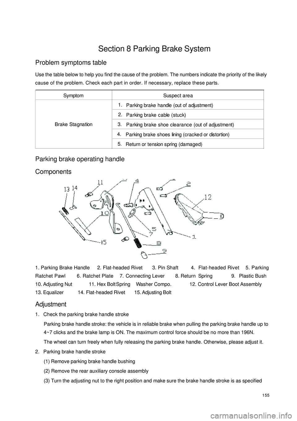
155Section 8 Parking Brake SystemProblem symptoms tableUse the table below to help you find the cause of the problem. The numbers indicate the priority of the likely
cause of the problem. Check each part in order. If necessary, replace these parts.Parking brake operating handle
Components1. Parking Brake Handle 2. Flat-headed Rivet 3. Pin Shaft 4. Flat-headed Rivet 5. Parking
Ratchet Pawl 6. Ratchet Plate 7. Connecting Lever 8. Return Spring 9. Plastic Bush
10. Adjusting Nut 11. Hex Bolt Spring Washer Compo. 12. Control Lever Boot Assembly
13. Equalizer14. Flat-headed Rivet15. Adjusting BoltAdjustment1. Check the parking brake handle stroke
Parking brake handle stroke: the vehicle is in reliable brake when pulling the parking brake handle up to
4~7 clicks and the brake lamp is ON. The maximum control force should be no more than 196N.
The wheel can turn freely when fully releasing the parking brake handle. Otherwise, please adjust it.
2. Parking brake handle stroke
(1) Remove parking brake handle bushing
(2) Remove the rear auxiliary console assembly
(3) Turn the adjusting nut to the right position and make sure the brake handle stroke is as specifiedSymptom Suspect area1. P a rking bra ke ha ndle (out of a djustme nt)2. Parking brake cable (stuck)3. Parking brake shoe clearance (out of adjustment)4. P a rking bra ke shoes lining (crac ke d or distortion)5. Return or tension spring (damaged) Brake Stagnation
Page 163 of 392
156(4) Install auxiliary console rear assembly
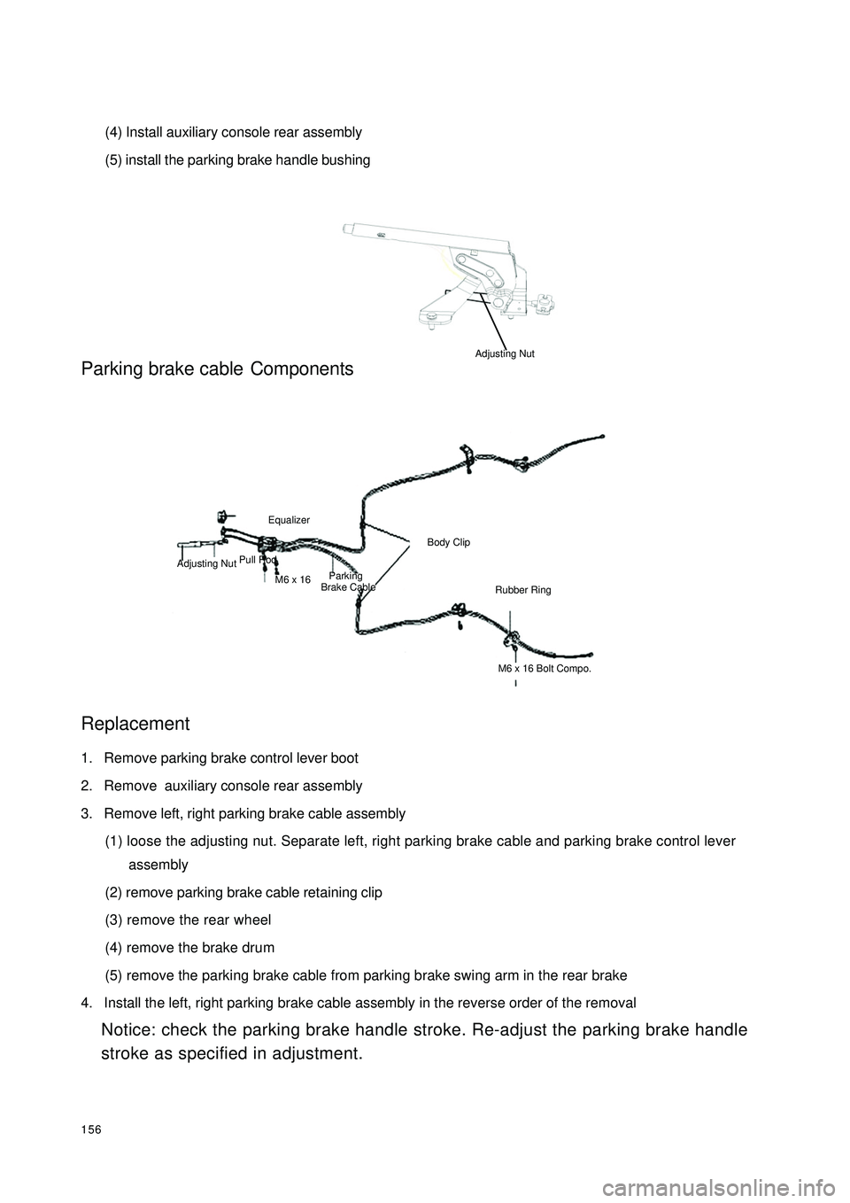
(5) install the parking brake handle bushingParking brake cableComponents
Replacement1. Remove parking brake control lever boot
2. Remove auxiliary console rear assembly
3. Remove left, right parking brake cable assembly
(1) loose the adjusting nut. Separate left, right parking brake cable and parking brake control lever
assembly
(2) remove parking brake cable retaining clip
(3) remove the rear wheel
(4) remove the brake drum
(5) remove the parking brake cable from parking brake swing arm in the rear brake
4. Install the left, right parking brake cable assembly in the reverse order of the removal
Notice: check the parking brake handle stroke. Re-adjust the parking brake handle
stroke as specified in adjustment.Pull RodEqualizerM6 x 16 Adjusting NutParking
Brake CableBody ClipRubber RingM6 x 16 Bolt Compo.Adjusting Nut
Page 164 of 392
157Part III Electrical EquipmentChapter 1 SurveyThis part refers to the electrical repair of the Free Cruiser, and analyzes the faults from every system. Then
some practicable diagnosis procedure and repair ways are given.I. HAND-HELD TESTER1. Before the tester is used, a through reading of the Tester Operation Manual is commended.
2. Connect the tester to the diagnosis interface with a wire. Turn the ignition switch ON. At this time, if the
tester and ECU control system cannot communicate, the vehicle or the tester may have faults.
(1) Connect the tester lead wire to another vehicle. If the communication is normal, inspect the vehicle
diagnosis Busline or power supply circuit.
(2) If it still cannot communicate when connecting to the other vehicles, it may have faults on tester itself.
Consult the self-inspecting procedure described on the Tester Operation ManualII. HOW TO PROCEED WITH TROUBLESHOOTINGThe basic operation procedure for troubleshooting is as follows.
1. Customer fault analysis
(a) Ask the customer for the conditions and environment when faults happen.
2. Confirm the fault symptoms, and check the DTCs and storage data.
(a) Check the battery positive voltage (Voltage: 10 - 14V when the engine is stopped.)
(b) Inspect the harness, connector and fuse for open and short, etc. by their appearance.
(c) Warm up the engine temperature to the normal operation temperature.
(d) Confirm the fault symptoms and check the DTCs.
(e) Confirm the test procedure for the parts or systems that need checking.
3. Circuit or part inspection
4. Repair
5. Test for checking
(a) After the repair is completed, verify if the fault has been removed.
(If the fault has not appeared yet, a verifying test should be done under the same conditions and environment
when the fault first occurred.)
Page 165 of 392
158III. CUSTOMER FAULT ANALYSISNOTES:
1. When the troubleshooting analysis is underway, make sure to confirm the fault symptom correctly. Re-
move kinds of suppositions in order to make an exact judgment. In order to find out what on earth the fault is,
it is extremely important to ask customers about the fault symptoms and the conditions when faults occurred.
2. The 5 items below are the key points to analyze. Those faults that were considered irrelevant and the
repair history, etc are sometimes helpful. Therefore, try your best to collect relevant information, and find out
the relationship between the information you collected and the present information, in order to make refer-
ence in troubleshooting.
Key points of the Customer fault analysis:
1Vehicle model, system name
2Date, time, frequency fault occurs
3 Pavement conditions
4Running performance, driving and weather conditions
5Fault symptomIV. FAULT SYMPTOM AND DTCSNOTES:
1. The diagnosis system of the Free Cruiser possesses many features. The first important feature is the DTC
Checking. Input a fault from the ECU signal circuit in the form of code, and store it into the ECU memory.
The other feature is Input Signal Inspection. Inspect if the signals from different switches are correctly
inputted into the ECU. These features can quickly narrow the range of troubleshooting, to make an efficient
troubleshooting analysis. In the model of Free Cruiser, the systems below all possess the diagnosis feature.
1EFI system
2 ABS system
3Supplemental Restraint System (SRS)
2. When a DTC is checked, the very important point is: make sure if the fault shown by a DTC still exists, but
is normal now. In addition, when checking the fault symptom, you must check if there is direct relationship
between the fault shown by the DTC and the fault symptom. Therefore, the DTC should be checked before
and after confirming the fault symptom in order to confirm the present conditions. If you do not do so, it is
possible to make some unnecessary troubleshooting analysis on normal systems in some certain circumstances,
thus making it more difficult to locate the fault or repair according to the fault. So, a DTC check should be
done by a normal procedure.
3. The procedure below shows how to make a troubleshooting analysis by checking a DTC and how to make
efficient use of DTC check. Then carefully check the result, make a troubleshooting analysis of the DTC and
a troubleshooting analysis of the symptom.
1Inspect DTC
2Record and clear all DTCs
3Confirm fault symptom
Page 166 of 392
1594Make a simulation test in a way of symptom simulation
5Inspect DTC
6Confirm symptomV. SYMPTOM SIMULATIONNOTES:
The most difficult conditions to handle in the fault troubleshooting are that the fault symptom dose not appear.
Under the circumstances, make sure first to make a comprehensive analysis to the fault described by the
customer, then to simulate an environment that is similar or the same with the conditions when the fault of the
customer's vehicle occurred. No matter how rich the experience of the technician is and how skillful he is, if
he make a fault troubleshooting analysis without confirm the fault symptom, it is inevitable for him to neglect
some important factors and incorrectly guess, which may cause barriers to repair. For example, if a fault
occurs only when the engine is cool or if a fault occurs only caused by a vibration from pavement and so on,
when the engine is checked in the hot or static state, it is no way to confirm. Because of vibration, high-
temperature or seeping water (Vapor) often causes some faults that are difficult to reappear. So, here are
some effective symptom simulation tests.
KEY POINTS OF SYMPTOM SIMULATION TEST:
In the symptom simulation test, no doubt it is important to confirm the fault symptom, but the fault position or
fault components must be also found out. So, before the test and the pre-inspection of connection, narrow the
range of the circuit where faults may occur according to the fault symptom. Then make a symptom simula-
tion test to see if the circuit measured is normal; the fault symptom is also verified at the same time.
1. Way of Vibration: When vibration may be the major cause of the fault.
For example:
(a) Use your hand to gently vibrate the sensor that is considered the cause of the fault, in order to check if it
is ineffective.
(b) Softly rock the connector and harness in horizontal and vertical direction.
Notes: Hard rock may cause the relay circuit open.
2. Way of Spraying Water: When rainy weather or wet environment may be the major cause of the fault.
(a) Spray water on the vehicle to check if the fault occurs.
NOTES:
�yBe sure not to directly spray water into the engine compartment. Spray the water on the face of the
radiator to change the temperature and humidity indirectly.
�yBe sure not to spray water onto electronic devices and controllers.
Page 167 of 392
1603. Way of Heating: When getting warm in the suspected area may be the major cause of the fault.
(a) Use a drier or other similar tool to heat the suspected area to check if the fault occurs.
NOTES:
�yThe heating temperature must be less than 60¡æ £¨140¨H£©(The temperature shall not exceed
the one that can damage the component.)
�yDo not directly heat the ECU parts.
4. Another way: When electrical overload may be the major cause of the fault.
�y Connect all electrical loads to check if the fault occurs.
Page 168 of 392
161Chapter 2 Starting and Charging SystemSection 1 Starting System
(MR479Q MR479QA MR481QA)I. STARTER INSPECTIONNOTICE:
These tests must be done within 5 seconds to avoid burning out the coil.
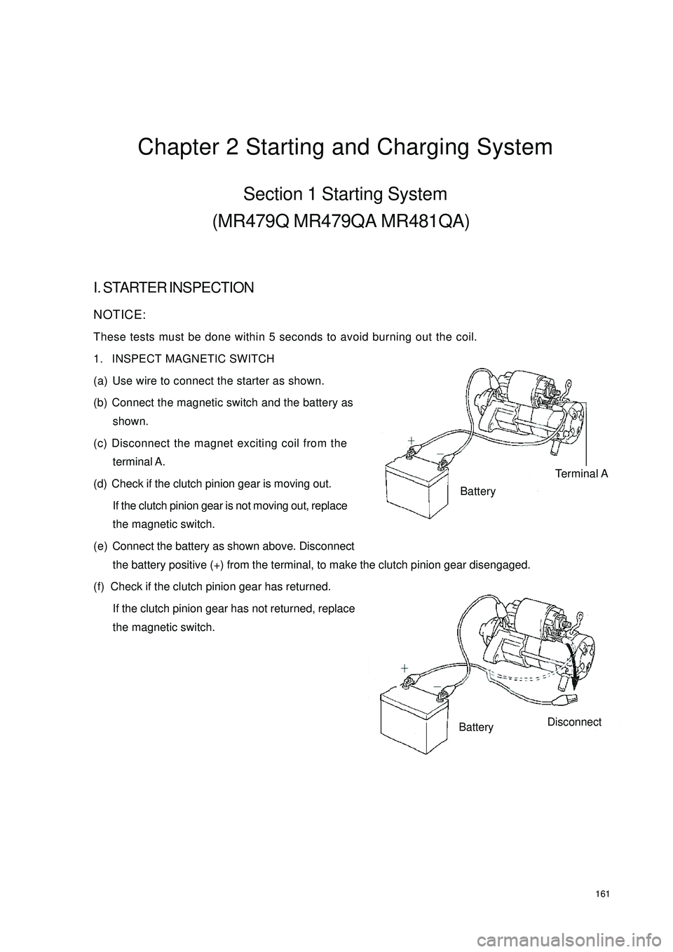
1. INSPECT MAGNETIC SWITCH
(a) Use wire to connect the starter as shown.
(b) Connect the magnetic switch and the battery as
shown.
(c) Disconnect the magnet exciting coil from the
terminal A.
(d) Check if the clutch pinion gear is moving out.
If the clutch pinion gear is not moving out, replace
the magnetic switch.
(e) Connect the battery as shown above. Disconnect
the battery positive (+) from the terminal, to make the clutch pinion gear disengaged.
(f) Check if the clutch pinion gear has returned.
If the clutch pinion gear has not returned, replace
the magnetic switch.Terminal ABatteryBatteryDisconnect
Page 169 of 392
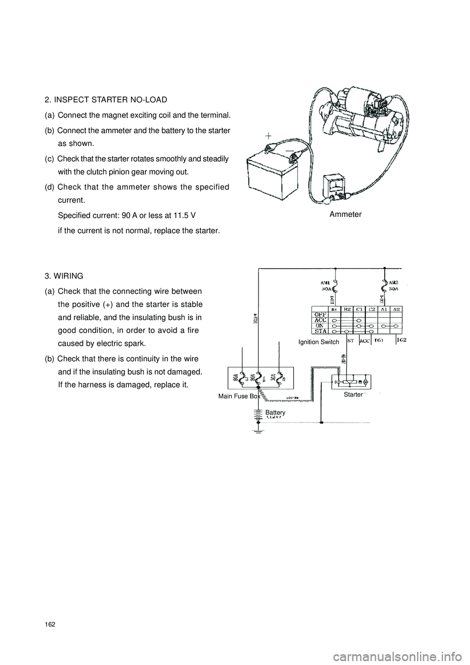
1622. INSPECT STARTER NO-LOAD
(a) Connect the magnet exciting coil and the terminal.
(b) Connect the ammeter and the battery to the starter
as shown.
(c) Check that the starter rotates smoothly and steadily
with the clutch pinion gear moving out.
(d) Check that the ammeter shows the specified
current.
Specified current: 90 A or less at 11.5 V
if the current is not normal, replace the starter.
3. WIRING
(a) Check that the connecting wire between
the positive (+) and the starter is stable
and reliable, and the insulating bush is in
good condition, in order to avoid a fire
caused by electric spark.
(b) Check that there is continuity in the wire
and if the insulating bush is not damaged.
If the harness is damaged, replace it.AmmeterIgnition SwitchBattery Main Fuse BoxStarter
Page 170 of 392
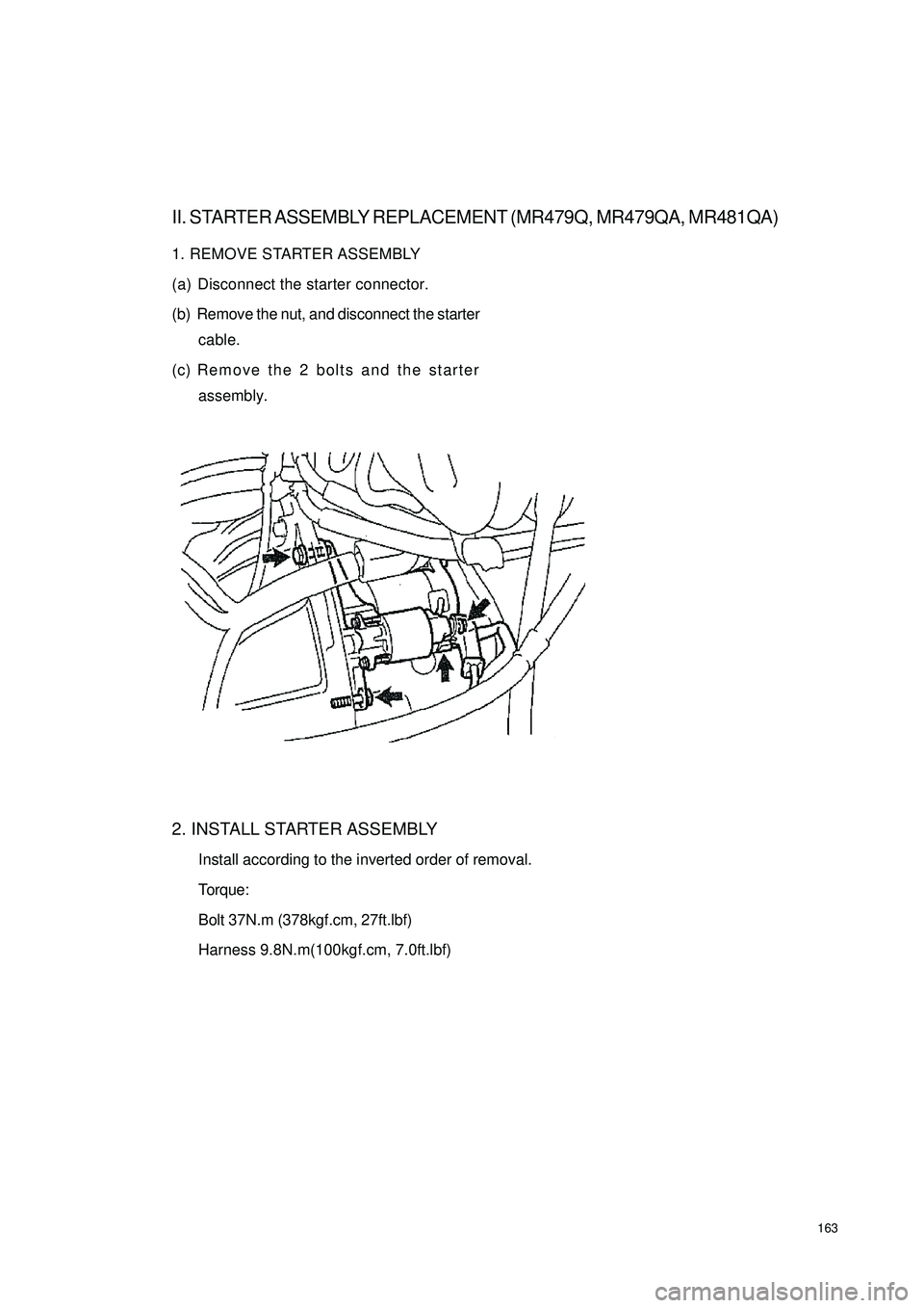
163II. STARTER ASSEMBLY REPLACEMENT (MR479Q, MR479QA, MR481QA)1. REMOVE STARTER ASSEMBLY
(a) Disconnect the starter connector.
(b) Remove the nut, and disconnect the starter
cable.
(c) Remove the 2 bolts and the starter
assembly.
2. INSTALL STARTER ASSEMBLY
Install according to the inverted order of removal.
Torque:
Bolt 37N.m (378kgf.cm, 27ft.lbf)
Harness 9.8N.m(100kgf.cm, 7.0ft.lbf)