GEELY CK 2008 Workshop Manual
Manufacturer: GEELY, Model Year: 2008, Model line: CK, Model: GEELY CK 2008Pages: 392, PDF Size: 38.86 MB
Page 171 of 392

164Section 2 Charging System
(MR479Q, MR479QA, MR481QA)I. BATTERYMaintenance-free battery is applied in this vehicle. Its termination voltage is 12V. It is connected inline by six
2V single cell in tandem with walls between every pole.
1. BATTERY WARNING SIGNS
1 -- Danger of corrosion
The battery electrolyte is very corrosive. DO NOT overturn the battery.
2 -- Read the instructions for battery
3 -- Children are forbidden to touch the battery
4 -- Avoid fire, electromagnetic wave and strong light.
Avoid electric spark while repair; avoid short.
5 -- Wear protecting glasses
6 -- Danger of explosion
The explosive mixed gas will be produced while charging.
7 -- How to deal with a scrapped battery
The scrapped battery should be delivered to the collection station.1234567
Page 172 of 392

1652. BATTERY REMOVAL AND INSTALLATION
HINT:
(1) The battery is not allowed to contact lubricating grease.
(2) The battery terminal is only allowed to be softly pulled out, in order to void damaging the battery.REMOVAL(1) Remove the negative (-) ground cable
(2) Remove the battery positive (+) cable
(3) Loosen the fixing clamp on the battery.INSTALLATIONInstall according to the inverted order of removal.
Tighten the torque
Tighten the battery cable clip to 6N.m (61kgf.cm, 4ft.lbf)
Tighten the fixing clamp to 12N.m (123kgf.cm, 8.6ft.lbf)
Page 173 of 392

166II. CHARGING SYSTEM INSPECTION1. CHECK BATTERY WORKING VOLTAGE
(a) After having driven the vehicle and in the case that 20 minutes have not passed after having stopped the
engine, turn the ignition switch ON and turn on the electrical system (headlight, blower motor) for 60
seconds to remove the surface charge.
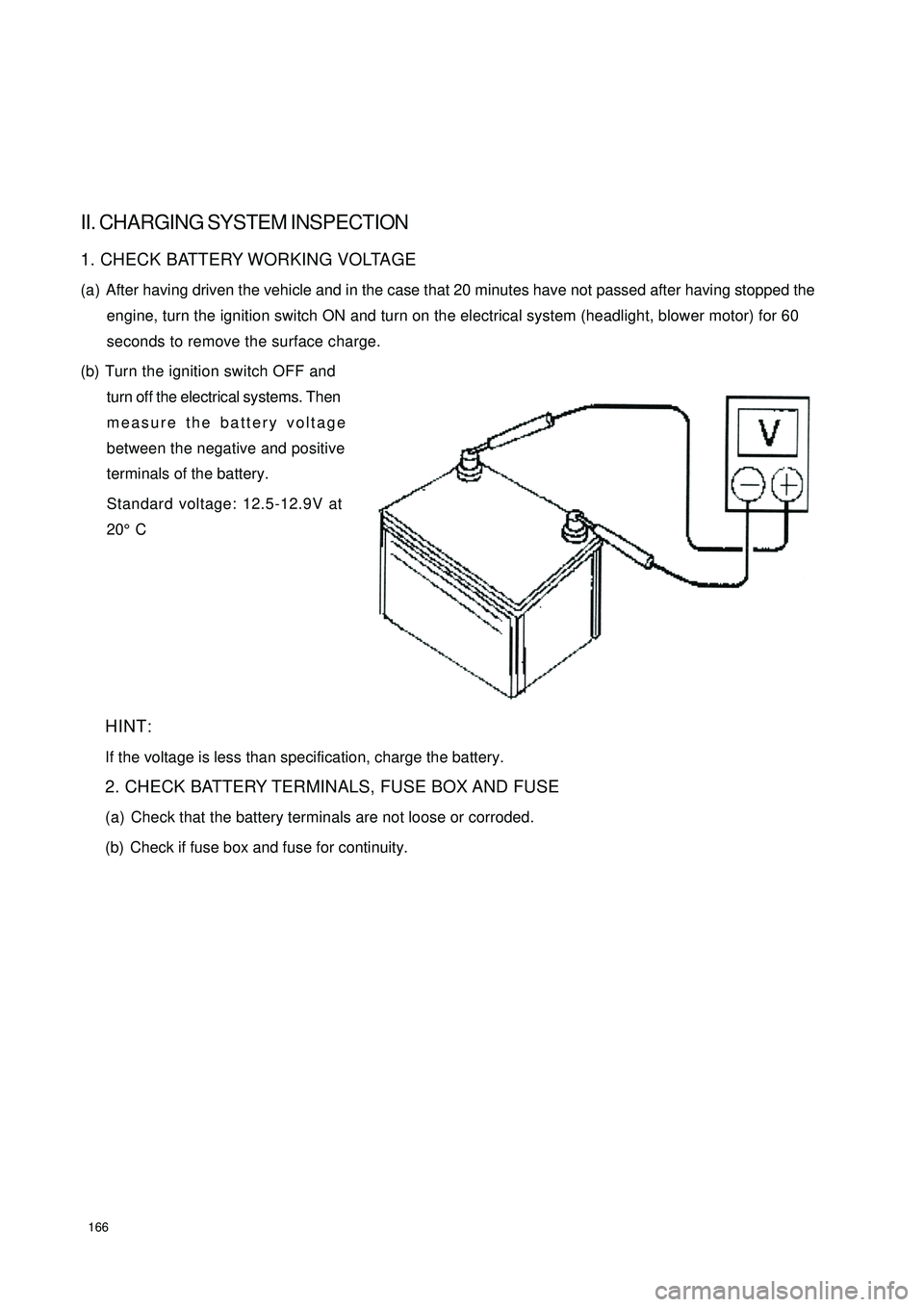
(b) Turn the ignition switch OFF and
turn off the electrical systems. Then
measure the battery voltage
between the negative and positive
terminals of the battery.
Standard voltage: 12.5-12.9V at
20°C
HINT:
If the voltage is less than specification, charge the battery.
2. CHECK BATTERY TERMINALS, FUSE BOX AND FUSE
(a) Check that the battery terminals are not loose or corroded.
(b) Check if fuse box and fuse for continuity.
Page 174 of 392

1673. INSPECT DRIVE BELT
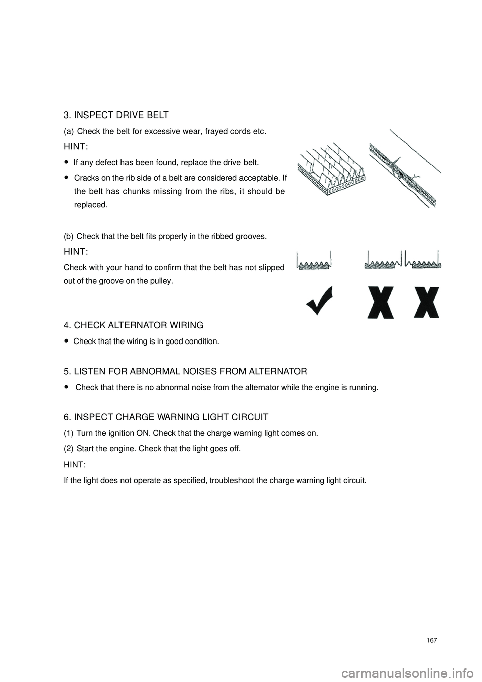
(a) Check the belt for excessive wear, frayed cords etc.
HINT:
�yIf any defect has been found, replace the drive belt.
�yCracks on the rib side of a belt are considered acceptable. If
the belt has chunks missing from the ribs, it should be
replaced.
(b) Check that the belt fits properly in the ribbed grooves.
HINT:
Check with your hand to confirm that the belt has not slipped
out of the groove on the pulley.
4. CHECK ALTERNATOR WIRING
�yCheck that the wiring is in good condition.
5. LISTEN FOR ABNORMAL NOISES FROM ALTERNATOR
�y Check that there is no abnormal noise from the alternator while the engine is running.
6. INSPECT CHARGE WARNING LIGHT CIRCUIT
(1) Turn the ignition ON. Check that the charge warning light comes on.
(2) Start the engine. Check that the light goes off.
HINT:
If the light does not operate as specified, troubleshoot the charge warning light circuit.
Page 175 of 392

1687. INSPECT CHARGING CIRCUIT WITHOUT LOAD
(a) If a battery/starter tester is
available, connect the tester to the
charging circuit as per instructions.
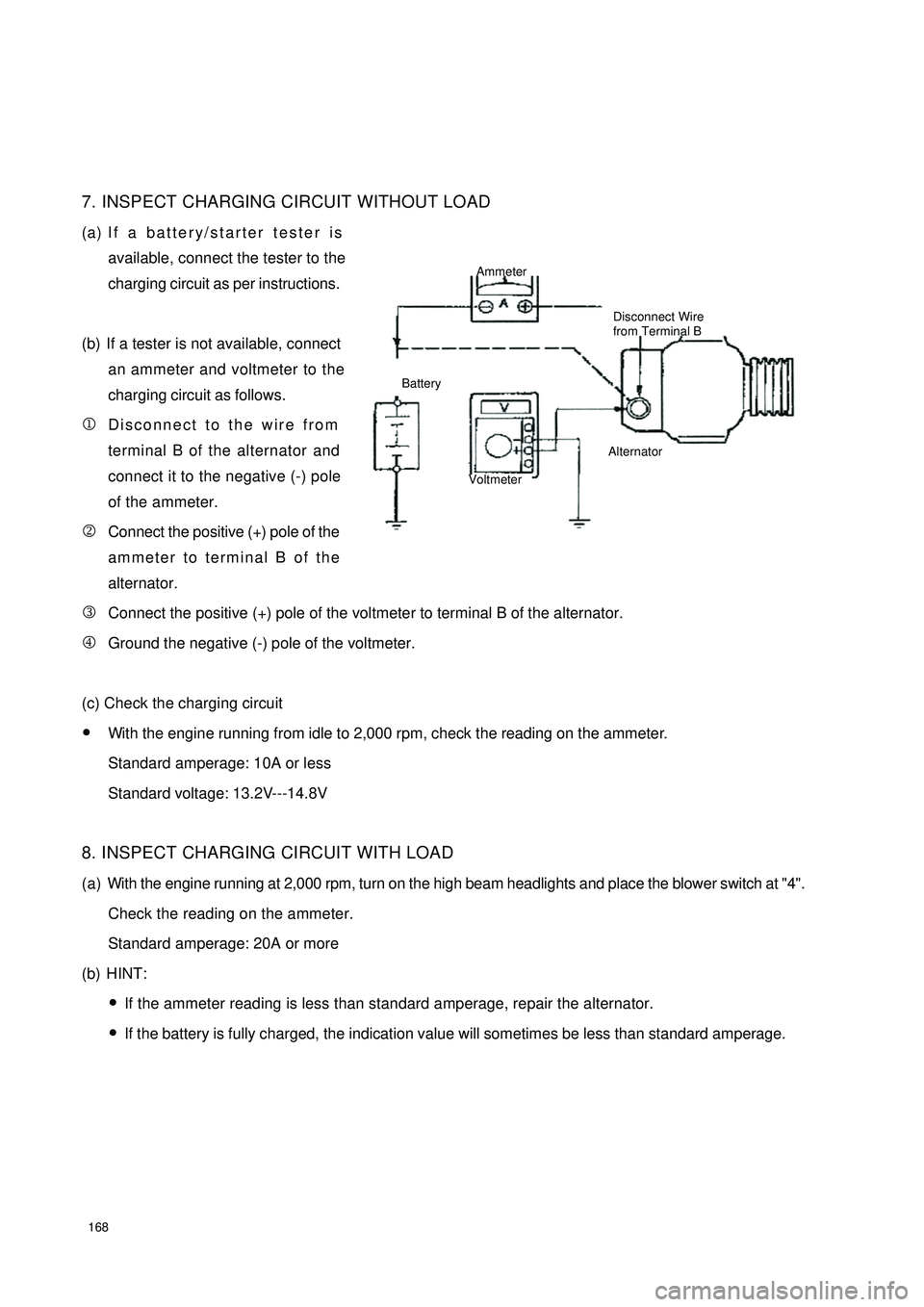
(b) If a tester is not available, connect
an ammeter and voltmeter to the
charging circuit as follows.
1Disconnect to the wire from
terminal B of the alternator and
connect it to the negative (-) pole
of the ammeter.
2Connect the positive (+) pole of the
ammeter to terminal B of the
alternator.
3Connect the positive (+) pole of the voltmeter to terminal B of the alternator.
4Ground the negative (-) pole of the voltmeter.
(c) Check the charging circuit
�yWith the engine running from idle to 2,000 rpm, check the reading on the ammeter.
Standard amperage: 10A or less
Standard voltage: 13.2V---14.8V
8. INSPECT CHARGING CIRCUIT WITH LOAD
(a) With the engine running at 2,000 rpm, turn on the high beam headlights and place the blower switch at "4".
Check the reading on the ammeter.
Standard amperage: 20A or more
(b) HINT:
�yIf the ammeter reading is less than standard amperage, repair the alternator.
�yIf the battery is fully charged, the indication value will sometimes be less than standard amperage.Ammeter
Disconnect Wire
from Terminal B
Battery
VoltmeterAlternator
Page 176 of 392

169III. ALTERNATOR INSPECTION1. INSPECT ALTERNATOR
Structure of Alternator
(a) Inspect the rotor winding
1Inspect the resistance of the rotor winding
Place the multimeter at R x 1, connect 2 pens and 2 slip
rings of the rotor.
Standard resistance: 2.7---3.1¸
2Inspect the rotor bending
Standard: less than 0.5 mm of radial motion
If it is not normal, calibrate or replace the rotor.PulleyBearing CoverBearing Rotor
Wire ClampBrush
GasketRectifier FrameConnecting InsulatorBrush
HolderBrush
HolderCoverRear Cover Bearing Retainer
Bearing
IC RegulatorRotor Winding Inspection Ω
Page 177 of 392

170(b) Inspect the stator winding
1Inspect the resistance of the stator winding
Place the multimeter at R x 1, connect 2 pens of the
meter to any of the 2 pens wires of the armature winding
respectively. There must be continuity. Where the
resistance reading is infinitely great shows an open circuit.
2Inspect the winding ground
Place the multimeter at R x 1, connect one pole of the
meter to the pole wires of the armature winding
respectively and the other pole of the meter to the stator
core. If the resistance reading is infinitely great, the
armature winding is well-insulated. If not, it needs repairing
and replacing.IV. ALTERNATOR ASSEMBLY REPLACEMENT (MR479Q, MR479QA, MR481QA)(a) Disconnect the alternator connector.
(b) Loosen the Bolt A, B, C
(c) Loosen the V-belt. Then remove the alternator.
2. INSTALL ALTERNATOR ASSEMBLY
Torque:
M10 bolt 15N.m (154kgf.cm, 9ft.lbf)
Tension adjustment for V-belt:
When the center of the belt receives a 50N of downward pressure, there is a 10 mm of deflection.AlternatorInspection of Armature Winding Ground
Page 178 of 392

171Chapter 3 Combination Meter SystemSection 1 Circuit Diagram of Combination Meter and Location of
Multi-pin Plug-in TerminalI. CIRCUIT DIAGRAM OF CONBINATION METERSpeed Signal
Ground The Sensor
Revolution SignalWater Temperature SignaFuel Level GaugeTachometer
SpeedometerWater
Temperature Gauge
Feul Level Gauge
OdometerHigh Beam Lamp
Rear Defrost Lamp
Rear Defog Lamp
Backlight
Water Temperature WarningPower Steering
Fuel WarningCharge
Brake Fluid
Oil Pressure
Engine Malfunction
Driver's seat belt
Park Brake
SRS(main)
SRS(sub)
Page 179 of 392

172II. LOCATION OF HARHESS MULTI-PIN PLUG-IN TERMINAL(1) HINT:
R -- RE Bl -- BLUE Y -- YELLOW
B -- BLACK P -- PIN G -- GREEN
W -- WHITE O -- ORANGE Gr -- GRAY
Br -- BROWN V -- VIOLETL g -- LIGHT GREEN
The first letter represents the base color
The second letter represents the color of the stripe
e.g. VG (violet & green) V-violet, G-greenColor of connector A is white, and B is blackVG
Page 180 of 392

1732. DEFINITION OF MULTIPIN PLUG-IN TERMINALDefinition of Terminal Color of Harness
1Empty
2EPS VG
3Empty
4Empty
5Empty
6Empty
7Empty
8 Combination switch (Position lamp P
9 Speed sensor groun B
10 Speed sensor power sourc RY
11 Speed sensor signal outpu YR
12 Fuel senso B
13 Alte rna tor WR
14 Brake fluid level switc GR
15 Oil pressure switc YG
16 Re a r de frost YB
1 Rear fog lamp Gr
2 Engine ma lfunc tion GY
3 S e a t be lt s w it c h R
4 P owe r sourc e Y
5 Engine coolant temperature senso YW
6 Park switch G
7 Power source groun B
8 Power source groun B
9ABS R
10 SRS (Ma in) RY
11 Engine re volution signa l BBl
12 Live wire (Fire wire) WG
13 High be am la mp + RB
14 Low bea m - RW
15 SRS (Sub) RG
16 Empty Terminal No.
A
B