HONDA INTEGRA 1994 4.G Workshop Manual
Manufacturer: HONDA, Model Year: 1994, Model line: INTEGRA, Model: HONDA INTEGRA 1994 4.GPages: 1413, PDF Size: 37.94 MB
Page 251 of 1413
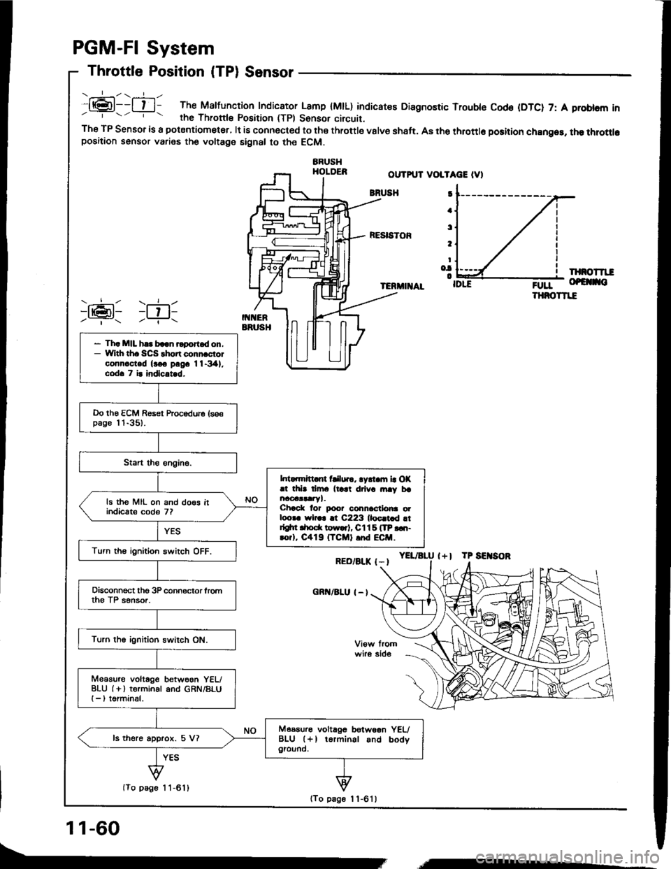
.:-\.-----ll@l--l t l- The Malfunction Indicator Lamp (MtL) indicatee Diagnostic Trouble Cod€ (DTC) 7: A problcm inrhe Thronle Position (TPl Sonsor circuit.The TP Sensor is a potsntiometer, lt is connected to the throttle valve shaft. A8 the throttlo position chan96, the throttlopositaon sensor varies the voltage signal to the ECM.
BBUSHHOLDER
PGM-FI System
Throttle Position (TPl Sensor
OUTPUT VOLTAGE IV)
BNUSH
RESISTOF
IXNOTTII
TERMIIIAL;0rr- of€ no
THNOTTIE
YEL/aLU l+l TP SEITSOR
I
a
t
t
Io.|o
RED/BLK {-I
cnn/BLu I - l
)ran1 )ril-Y- -?..
- Th. MIL h.. baln rlport d on.- With th. SCS thort conn.ciolconn.c-ted (rco pngc 11-341.codo 7 i. indlc.t d.
Do the ECM Reset hocedure (se€page l 'l-35).
l. ..mrtt nt fClur., lyrt m la OX.t thb dm. ll.at drlv. rn.y brncoaataryl.Chack lor poo? connactlo|ra otloora wlr.r !t C223 lloc.t d !tdgtn drod( tow..t, Cl15 ITP ...t-rorl, C419 (TCMI .nd ECM.
ls the MIL on and do€s itindicats codo 7?
Turn th€ ignition switch OFF.
Disconnect tho 3P connector lromth€ TP sensor.
Turn the ignition switch ON.
Meosu.o voltage betwoon YEL/BLU (i ) terminal and GRN/BLUI -, torminal.
Measurs voltagG betw66n YEUBLU (+l terminal and bodygiound.ls there approx. 5 V?
(To page 1 1-611
11-60
(To page 1 1-6'l )
,,,----
Page 252 of 1413
(From1 1-60){From
A/T only
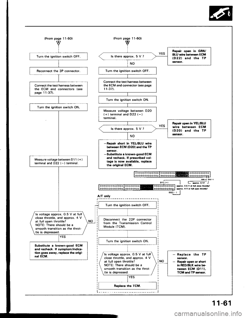
Turn the ignition switch OFF.
Connect the test harness betweenthe ECM and connectors (seepage 11-37l-.
Turn the ignilion switch ON.
Measure voltage between D1 1 {+ )terminal and 022 (- I terminal.
Turn the ignition switch OFF.
ls voltage approx. O.5 V at lullclose throtlle. and approx. 4 vat full open throttle?NOTE: There should be asmooth transition as the throt-tle is depressed.
Disconnect the 22P connectorfrom the Transmission ControlModule (TCM).
lurn the ignition switch ON.
Substitute a known-good ECMand roch6ck. ll symptom/indica-tion 9063 away, roplaco th6 origi-nal ECM.- Replaco tho TPaonsoa,- Repai. opon or ahonin RED/BLK wir. b€-twoon ECM lDl1l,TCM 6nd TP sonsor.
ls voltage approx. 0.5 V ar fullclose throttle, and approx. 4 Vat tull open throttle?NOTE: There should be asmooth transition as the throt'tle is deprossod.
page 1 1-60)
Repsir op.n in GRN/8LU wii6 botwoon ECMlD22l snd tho TPaenaot.
ls there approx. 5 V ?
Turn the ignition switch OFF.
Connect the test hamess betweenthe ECM and connector {see page11-37).
Turn the ignition switch ON.
Measure voltage between D2O{+) terminsl and D22 {-}termtnal,
Ropoi. open in YEL/BLUwire bgtween ECM{D20} and rho TP30naot.
ls there approx. 5 V 7
-ReDai. ahort in YEL/BLU wiroborwoon ECM (D2Ol and tho TPson30t.-Sub3tituto a known-good ECM6nd rochock. It prcacribod vol-t6go is now availablo, roplacoth6 original ECM.
Fr. o.5 v n tua .b drdn ?
11-61
Page 253 of 1413
PGM-FI System
Intake Air Temperature (lAT) Sensor
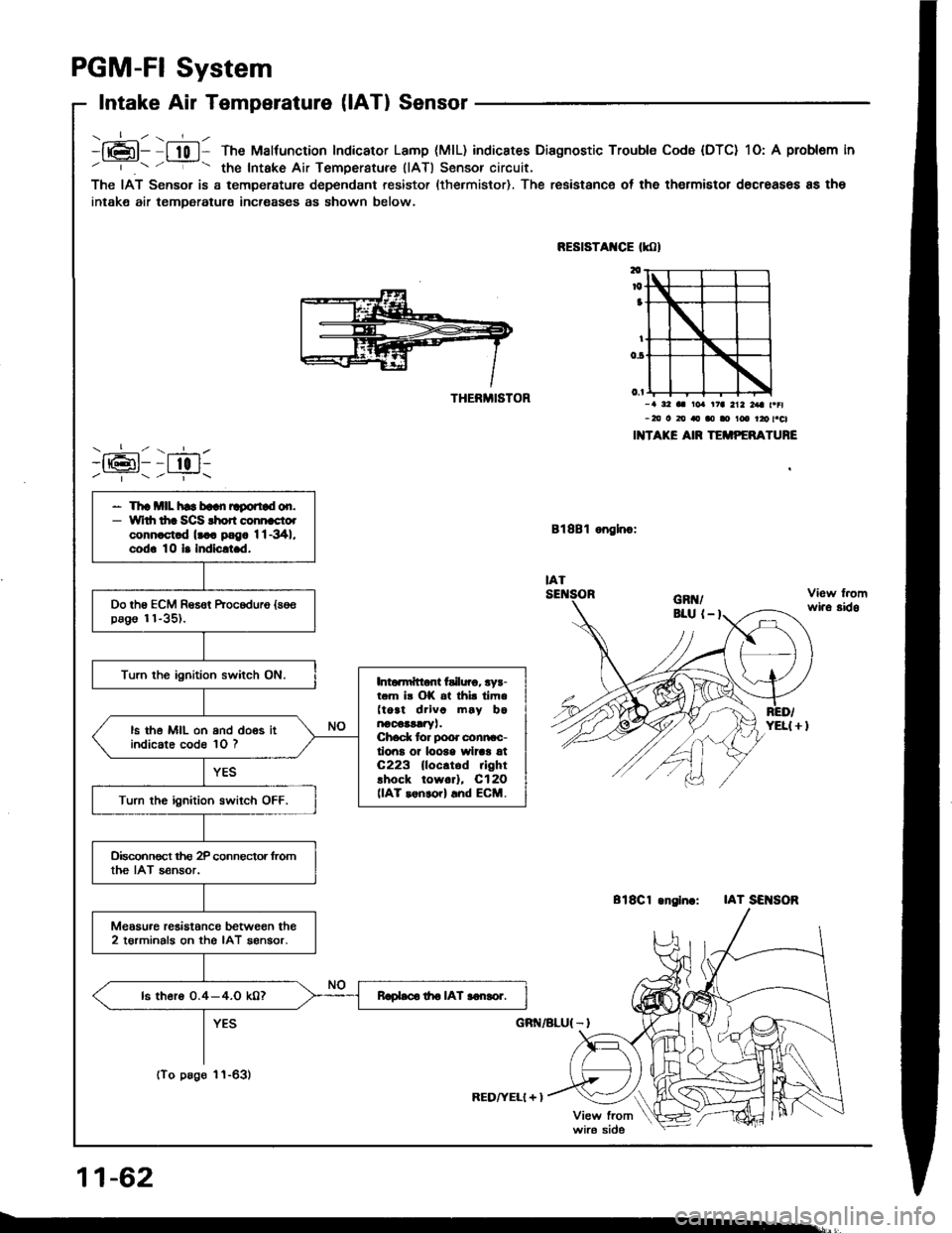
----:-- z ---L /-h6l- I t0 l- The Malfunction Indicator Lamp (MlL) indicstes Diagnostic Trouble Cod6 (DTC) 1O: A problem in/ | / - the Intake Air TemDerature (lAT) Sensor circuit,
The IAT Sensor is a temperature dependant resistor (the.mistor). The resistanc€ of the thermistor d6creases 8s the
intake air temDeratura incroases as shown below.
)1611:till/ ---l- z ---i-\
THERMISTOR
RED/YELI + )
RESTSTAXCE tmt
Bl8Bl onglnc:
-a a2 aa roa .t7a 212 a t |l-20 o 20 rto ao I t6 rro t.cl
I TAKE AIR TEiiIPTFATURE
818C1 .nglnc:IAT SEI{SOR
11-62
wi.a sido
- Th! *llL hs b!!n Egortad on.- \|
rdr dra SCS rhon connrcto.conn.ct.d lt . psg. 1l-341.cod. 10 l. hdlclt.d.
Do the ECM Resot kocoduro {se€pago 11-35).
Turn the ignition switch ON.Into.n{tlont failuro. rys-r.m ir OK .t thi. iim.(toat drlvc m6y b6arooa!!1ryt.Ched( tor poor clnncc-lioiE or loote wlrar 6tC223 lloc.tod rightlhock toworl, C12O(lAT renrcrl and ECM.
ls the MIL on and doos itindicate code 10 ?
Turn the ignition swiich OFF.
Oisconnoct tho 2P connector fromthe IAT sensor.
Meosu.e resistonc€ between the2 torminals on the IAT aengor.
ls thero 0.4-4.0 k0?Rlobco tho IAT aonsor.
(To pago 1'l-63)
Page 254 of 1413
{From pag6 l1-62}
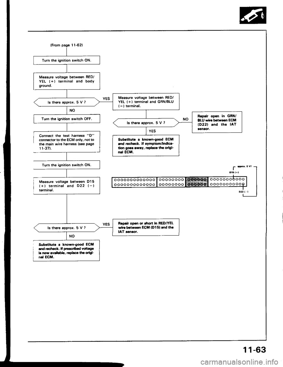
Turn the ignition switch ON.
Messuro voltage b€tw€6n RED/YEL (+) terminal and bodyground.
M€asurs voltage between RED/YEL {+) rerminal and GRN/BLU{ - I terminal,ls thore approx. 5 V ?
Rsp.lr op.n in GBt{/8LU wir bctwo.r ECM
lD22l snd tho IATaanaor.
Turn the ignition switch OFF.ls thero a99rox. 5 V ?
Sub.lhul. a tnown{ood ECMlnd rachack. It rymptom/lndlc!-don gort arv.y, t pl.c. dr! oilgl-n.l ECM.
Rap.lr opon or rhon In REDfYELwh. b.tw..n ECM lDl5l rnd th.lAf tcrrao.-ls th€re spprox. 5 V ?
Connsct lhg t€st hamess "D"
connoctor to the ECM only. not toth6 main wire harness lsse page
11-371.
Turn tho ignition switch ON.
Mgasur€ voltag€ bstwgon D15(+) terminal and D22 l-ltgrminal.
S0brlitrrt. . lnown{ood ECM'|d '.
Page 255 of 1413
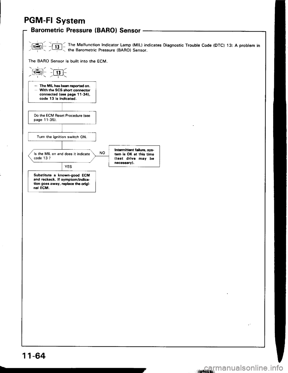
PGM-FI System
Barometric Pressure (BAROI Sensor
fAl- f;ff: The Maltuncrion Indicator Lamp (MtL) indicates Diagnostic Troubte Code (DTCI 13: A probtem inL--:g the Barometric Pressure {BARO) Sensor.
The BARO Sensor is built into the ECM.
-.+.-- \--r- /
t(gt -t 13 t-/'\/_i-\
- Tho MIL has booo reponod on.with th6 scs Short COnnOCtO.connoctod (aeo psgo 11-34),cod€ 13 is indicatod.
Do the ECM Reset Procedurc (seepage 1'l-35).
Turn the ignition switch ON.
Intormitt€nt trluro, sys-tem is OK !l this timo{le!t driv6 msy bonecoSaaiy).
ls the MIL on and does it indicatecode 13 ?
Substituto . knorvn-good ECMand reck6ck. lt symptom/indicr-tion goes away, roplaco th6 origi-nal ECM.
11-64
lrl$fiiHrfi.
Page 256 of 1413
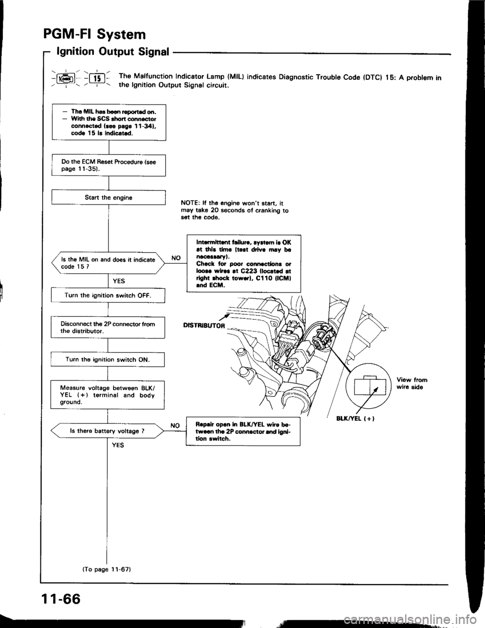
PGM-FI System
lgnition Output Signal
i16;11 :ffi1 The Malfunction Indicator Lamp (MlLl indic8tes Diagnostic Trouble Code (DTC) 15: A probl€m in'--=-- . -r- t the lgnition Output Signsl circuir.
I
NOTE| ll the onoine won't stan. itmay take 20 seconds ot cranking to5€t th€ COde.
D|STNIBUTOB
wir6 sido
- Th. MIL hsr b..n roport.d od.- Widr ths SCS .hon cohnecto.connoct€d {..o plgo 11-341,codg |5 i! indicatrd.
Do the ECM Reset ftocedure (seepage 'l'l-351.
Intarmltt nt hllur.. ryltam i. OK!t drlr dm. (t |l drlva mly bonaoaaalry).Chack tor Door cmnactiona orloo|. rYlrar !t C223 llocltld !trlghr .hoct tow.rl, Cl10 (lCMl.nd ECM.
ls th€ MIL on and do€s it indicatecode 15 ?
Turn the ignition swirch OFF.
Turn the ignition switch ON.
Measure voltage betwoon BLK/YEL (+) terminal snd bodygrouno.
R.p.ir op.n In BLK/YEL wlr. bo-ftvarn th. 2P conn.cior lnd ioni-tion rwitch.
ls the.e battory voltage ?
(To page 11-67)
11-66
re*,
Page 257 of 1413
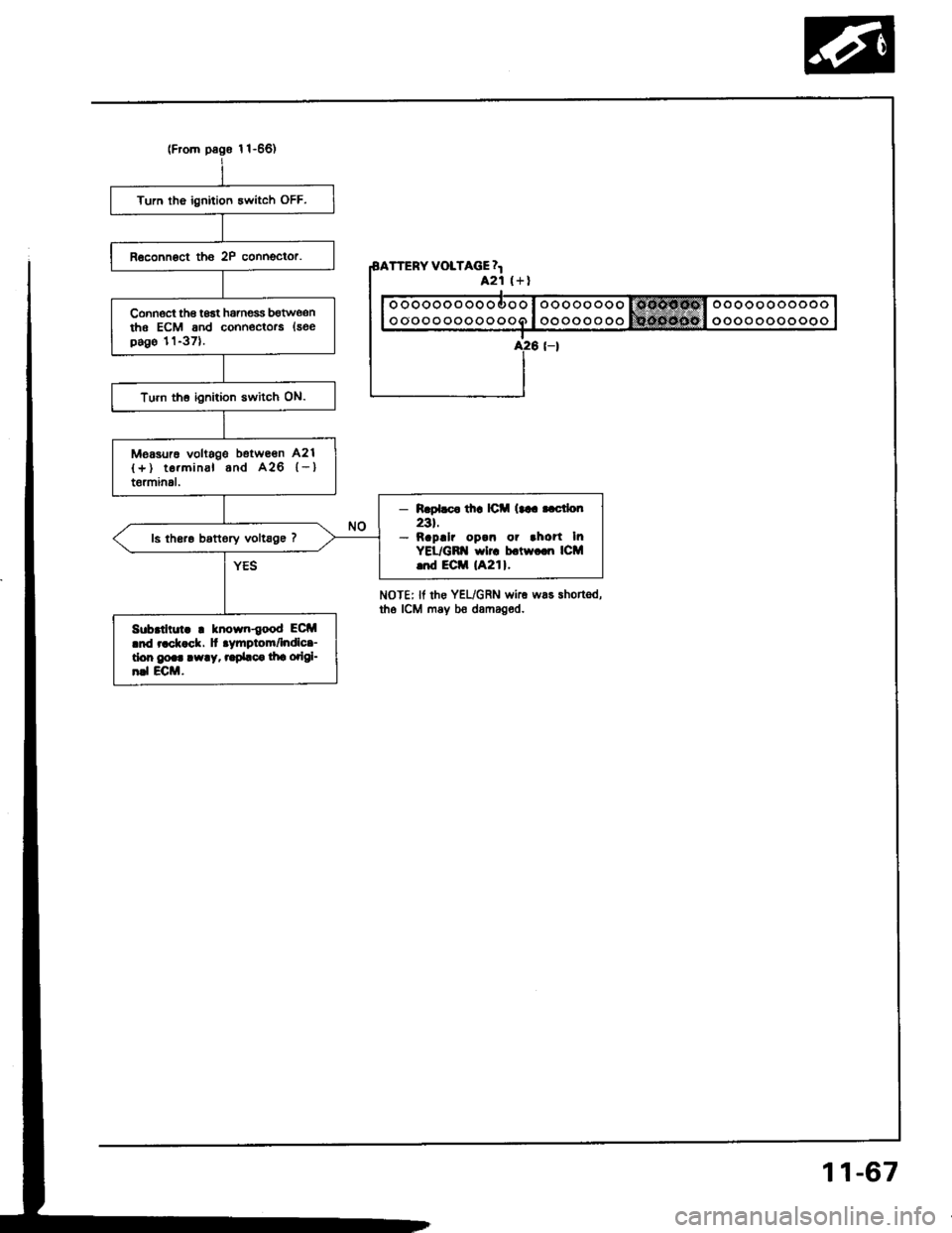
Turn tho ignition 3witch OFF.
Connoct th€ toat hamess bgtwe,snthe ECM and conn€ctors {seepago 11-371.
Turn th6 ignition switch ON.
Measurc voltags betwe€n A21
{+) te.minal and A26 {-}t6rminal.
- R.pl.c. th! lC (trr..ctlo[
23t.- napllr op.n or .ho?t InYEL/GB'{ wlrc b.tw.cn ICM..d Eciil lA21l.
ls th6re bottory vollsge 7
Sub.thut. ! known{ood ECM.nd r.ck ck. ]t .ymptom/lndlc.-don go.. !w!y, ..pbc. lha odgl-n.l ECM.
TTERY VOLTAGE 4421 (+l
ooooooooooooo
oooooooooooo
NoTEr lf rhe YEL/GRN wke was shortsd,tho ICM may bo damaged.
11-67
Page 258 of 1413
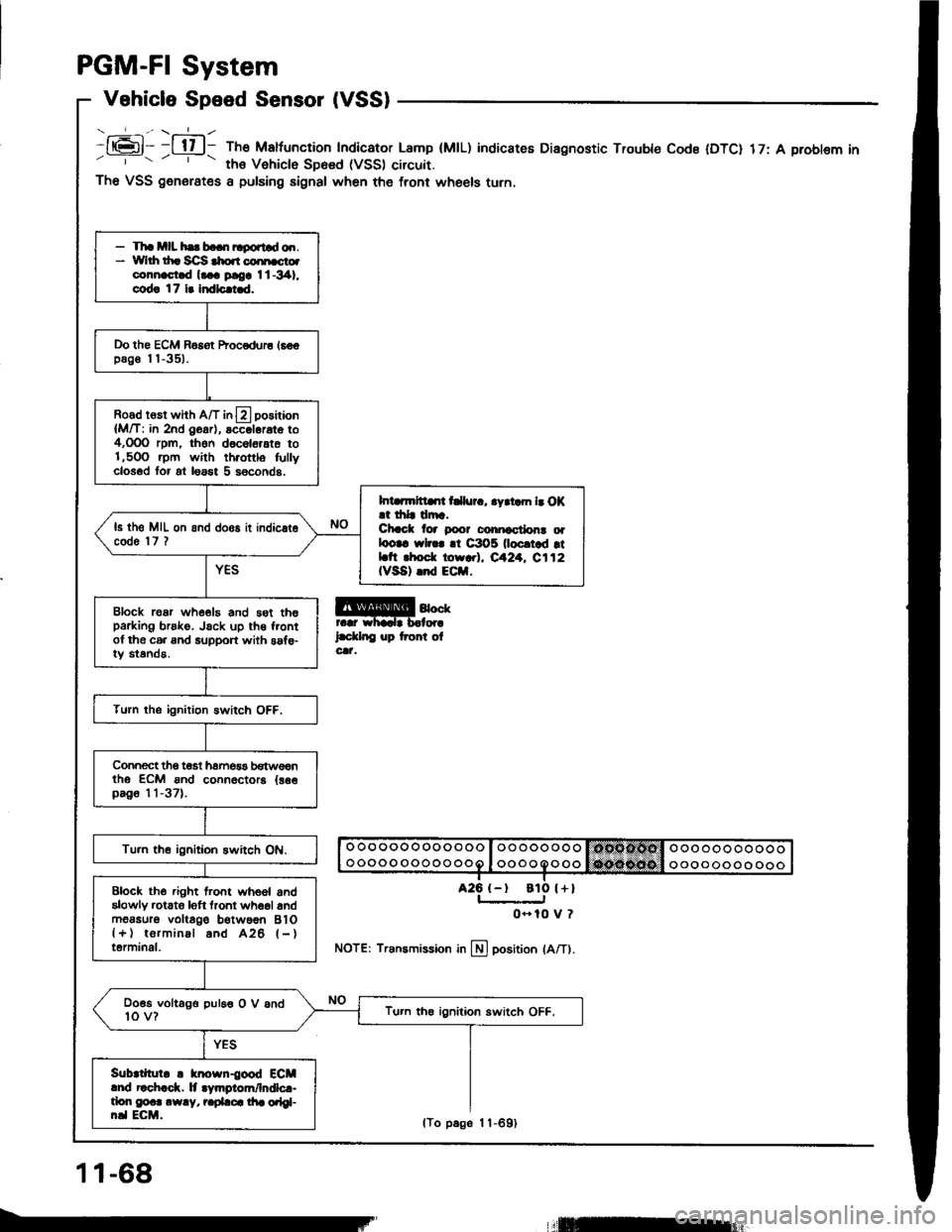
PGM-FI System
Vehicle Speed Sensor (VSS)
- _-_f_-., \-=1_ -
It6l- -l tl l- The Maltuncrion Indicator Lamp (MtL)' ths Vehiclo SD6sd (VSS) circuit.
indicateE Diagnostic Trouble Code IDTC) 17: A problem in
a25 {-t
The VSS generates a pulsing signal when the front wheels turn.
@4""rr.r whadr b.lor.
l.d.lnC up tront olcat,
NOTE: Transmission in llj position lA/Tl.
- Tha mll hs b..n ltgortld o.r.* Yvlrh th. Sc]S $o.r coi[cto.connast.d l... ploa I l -341,
cod! 17 i. Indlc.i.d.
Do the ECM Basot Procodur6 16€€pag€ I I -351.
Road rosr whh A/T in13 positaon
{M/T: in 2nd O6ar), accol6rat6 to4,OOO rpm, thon d6c6l6,ate to1,5OO .pm with th.ottlo fullyclosod tor at loast 5 s6conds.
Int rmltllrt t llur., .yrtam b O|(.t drlr drr.Chcct lor poor conicctlon! oalootc wl... !t C3O5 0ocrtad rtLtt rhod. torr.l, eA24. C112IVSA) .nd ECil.
ls th6 MIL on and doos it indic.t6code 'l7 ?
Block roar whe€19 and 5st th6parking brsko. Jsck up th€ f.ontof the c6. and support with saf€-iy standa.
Turn the ignition Bwitch OFF.
Connect tho t€st hamos3 b€tw€€ntho ECM ond connoctora {as€pag6 11-37).
Tu.n th€ ignitioh switch ON.
Block the .ight lront whoel andalowly rctato loft tront wh6ol andm6asur6 voltago b€twoon BlO{+) torminal and A26 l-}terminal.
Doss voltago puleo O V and10 v?Tu.n th€ ignition switch OFF.
Sub|tllul. ! knosn{ood ECMlnd r!ch.ck. lt .Vmgiom/lndlc.-tlon g@.. .w.y, r.pLca di. orlgl-n.l ECM.
ato l+l
0- 10 V ?
11-68
lTo p6ge 1 1-691
llEur
Page 259 of 1413
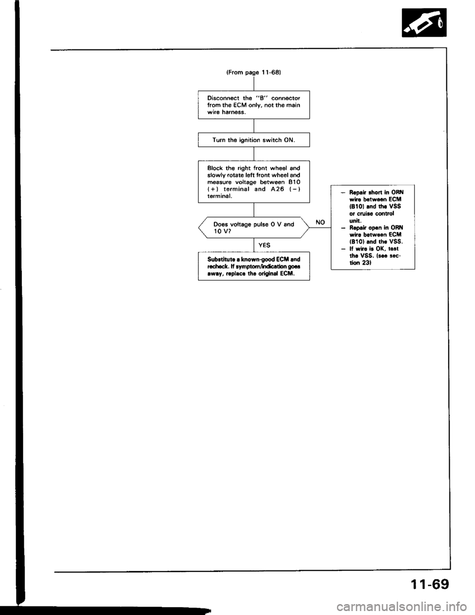
Disconnect the "B" connectorfrom the ECM only, not the mainwile hatness.
Turn the ignition switch ON.
Block tho right front who€l andslowlv rotate l6ft front wheel andm€asure voltage between 8'l Ol+) terminal and A26 (-)
terminal.- Roo.ir lhort in ORt{wire belween ECM18101 tnd rhs VSSor cruia6 controlunit.- ncp.i. op€n in ORI{wira botwoan ECM(8101 and the vSS.- It wir. i! OK, totttho vSS. lsoc aec-tion 231
Doos voltage pulso O V and'to v?
SubrtituL . known-good ECil lndEch.ck. fi lynptom/ndcltbn gp..
rw!y, .rpleco lh. original ECM.
(From page 1 1-68)
1 1-69
Page 260 of 1413
![HONDA INTEGRA 1994 4.G Workshop Manual PGM-FI System
Electrical Load Detector (ELDI
tft;-]/ The Maltunction Indicaror Lamp (MlL) indicatss Diagnostic Trouble Code IDTC) 20: A probtem in-Li!- tne Electrical Load Detecror {ELD} circuit.
With HONDA INTEGRA 1994 4.G Workshop Manual PGM-FI System
Electrical Load Detector (ELDI
tft;-]/ The Maltunction Indicaror Lamp (MlL) indicatss Diagnostic Trouble Code IDTC) 20: A probtem in-Li!- tne Electrical Load Detecror {ELD} circuit.
With](/img/13/6067/w960_6067-259.png)
PGM-FI System
Electrical Load Detector (ELDI
tft;-]/ The Maltunction Indicaror Lamp (MlL) indicatss Diagnostic Trouble Code IDTC) 20: A probtem in-Li!- tne Electrical Load Detecror {ELD} circuit.
With lho SCS lhon connectolconnoctod {ree pago 11-34}, cod.20 is indicatod.
Do the ECM B6set Procedurs {seepage 1 'l-35).
Start engine and keep engin€speed at idle.Turn on headlights.
lntennlna tlllure, lyrtom lt Ol(!t irl. dm. (lgtt driv. mly [email protected] for Door connactlona oaloota wiro. rt C218 IELD, lndEctrt.
Ooes the MIL indicato code 20?
Romove the undgr-hood fusg/relay box and remove the tus6/relav box lowet cover.
Turn lhe ignition switch ON.
Measure voltage betw€on BLK/YEL (+l terminal and BLK (-)terminal.
Msasuro voltag€ b€tweon BLK/Y€L {+) terminal snd bodvground.ls there bartory voltagel
Rcpir oo.n in BLK wir.batwaan lha 3P connrc-tor lnd G2Ol {loc.t.dtroit ot angh|. comprn-m.r dghl .ld.l,
B.p.lr op.n in BLKrYEL wlrr b.-tw..n o.24ACG (ALn flcl115A: Bl88l .ngln!, 20 A:818C1cnginol fu!. In thr und.r{..htu.o/r.lly bor lnd tho 3P con-rcclo?.
View tromwire side
BLK (-)
(To page 11-7'l)
GRn/iED I - |
BLK/YEL I + I
11-70