HONDA INTEGRA 1994 4.G Workshop Manual
INTEGRA 1994 4.G
HONDA
HONDA
https://www.carmanualsonline.info/img/13/6067/w960_6067-0.png
HONDA INTEGRA 1994 4.G Workshop Manual
Trending: rims, jack points, Oil capacity, windshield wipers, Starter relay, electrical connections, towing
Page 341 of 1413
spection
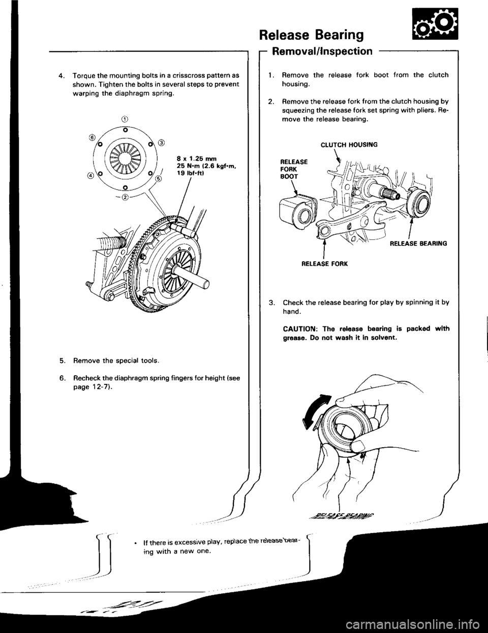
release fork boot trom the clutch4. Torque the mounting bolts in a crisscross pattern as
shown. Tighten the bolts in several steps to prevent
warping the diaphragm spring.
8 x 1.25 mm25 N.m 12.6 kgt'm,19 tbt.ftl
2. Remove the release tork trom the clutch housing by
squeezing the release fork set spring with pliers. Re-
move the release bearing.
Check the release bearing for play by spinning it by
hand.
CAUTION: The release boaring i6 packed with
grease. Do not wash it in solvent.
Remove the special tools.
Recheck the diaphragm spring fingers tor height (see
page 12-7]..
Release Bearing
Removal/ln
1. Remove the
housing.
CLUTCH HOUSING
RELEASE FORK
-24/--2,t'.2424?'
IJ
l{ there is excessive plaY, rep)ace the rdease\Ear-
ing with a new one.
,F=:=
Page 342 of 1413
Release Bearing
Installation
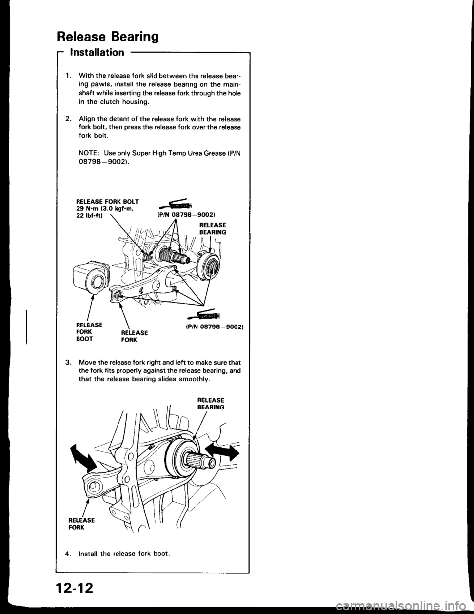
1.With the release tork slid between the release bear-
ing pawls, install the release bearing on the main-
shaft while inserting the release fo.k through the hole
in the clutch housing.
Align the detent ot the release fork with the release
tork bolt, then press the release fork over the release
fork bolt.
NOTE; Use only Super High Temp Urea G.ease (P/N
08798- 9002).
2.
-611
lPlN 08798-
-6
{P/N 0879a-9002)
Move the release fork right and left to make sure that
the fork tits properly against the release bearing, and
that the release bearing slides smoothly.
4. lnstall the release fork boot.
12-12
Page 343 of 1413
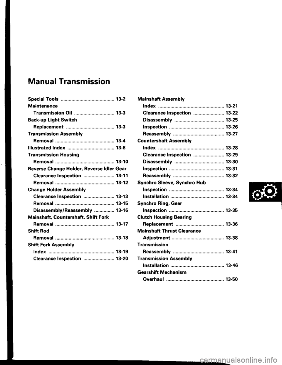
Manual Transmission
Special Toofs ............. 13-2
Maintenance
Transmission Oi1,...,........,........,.,..... 13-3
Back-up Light Switch
Replacement ......... 13-3
Transmission Assembly
Removal ..,.......,...... 13-4
lllustrated Index ................................... 13-8
Transmission Housing
Removal ...........,..... 13-10
Reverse Change Holder, Reverse ldler Gear
Glearance lnspestion ....................... 13-1 1
Removaf ................. 13-12
Change Holder Assembly
Clearance Inspection ....................... 1 3-1 3
Removal ................. 13-15
Disassembly/Reassembly ............... 13-16
Mainshaft, Gountershaft, Shift Fork
Removal ...,............. 13-17
Shift Rod
Removal ................. 13-18
Shift Fork Assembly
Index ................ ...... 13-19
Clearance Inspection ....................... 13-20
Mainshaft Assembly
Index ................ ...... 13-21
Clearance f nspection ....................... 13-22
Disassembly .......... 13-25
Inspection .............. 13-26
Reassembly ........... 13-21
Countershaft Assembly
Index ................ ...... 13-28
Clearance Inspection ....................... 13-29
Disassembly .......... 13-30
Inspection .............. 13-31
Reassembly ........... 13-32
Synchro Sleeve, Synchro Hub
Inspection .............. 13-34
Installation ............. 13-34
Synchro Ring, Gear
lnspection .............. 13-35
Clutch Housing Bearing
Replacement ......... 13-36
Mainshaft Thrust Clearance
Adiustment ............ 13-38
Transmission
Reassembly ........... 13-tl1
Transmission Assembly
lnstallation ............. 13-46
Gearshift Mechanism
Overhaul ................ 13-50
Page 344 of 1413
Special Tools
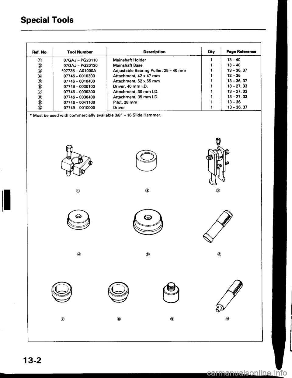
Rsf. No. I Tool NumbrrD!3criptionOty I Prgc R.{.rcnc.
o
o
o
o
@
@
@
@
@
07GAJ - PG20110
07GAJ - PG20130.07736 - A010004
07746 - 0010300
07746 - 0010400
07746 - 0030r00
07746 - 0030300
07746 - 0030400
07745 - 0041100
07749 - 0010000
Mainshaft Holder
Mainshaft Bas€
Adjustable Bearing Puller, 25 - 40 mm
Attachment, 42 x 47 mm
Attachment, 52 x 55 mm
Oriver, 40 mm l.D.
Attachment, 30 mm l.D.
Attachment, 35 mm l.D,
Pilot, 28 mm
Driver
1
1
1
1
1
1
1
1
1
1
'13 - 40
13-40
13 - 36, 37
13-36
13 - 36, 37
13 - 27,33
13 - 27,33
13 - 27,33
13-36
13 - 36, 37
* Must be used with commerciallv available 3/�8" - 16 Slide Hammer.
o@
@@@
o@@
ll
13-2
Page 345 of 1413
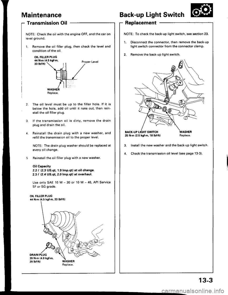
- Transmission Oil
NOTE: Check the oil with the engine OFF, and the car on
level ground.
1. Remove the oil filler plug, then check the level and
Maintenance
condition of the oil.
OIL FILLER PLUG44 N.m lia.5 kgf.m,
ORAIN PLUG$ N.m 14.0 kgf.m.29 lbf.fr)
33 tbtftlProper Level
2. The oil level must be up to the filler hole. lf it is
below the hole. add oil until it runs out, then rein-
stall rhe oil filler plug.
3. lf the transmission oil is dirty, remove the drain
plug and drain the oil.
4. Reinstall the drain plug with a new washer, and
refillthe transmission oil to the proper level.
NOTE: The drain plug washer should be replaced at
every oil change.
5 Reinstall the oil filler plug with a new washer.
OilCapacity
2.2 ( ''2.3 US.qt,1.9 lmp.qt) at oil chang€.
2-3 I l2.1Us.ql,2.0lmp.qtl at oyerhaul.
Use only SAE 10 w - 30 or '10 W - 40, API Service
SF or SG grade.
OIL FILLER PLUGa4 N.m l{.5 kgf.m, 33 lbf.ftl
Back-up Light Switch
Replacement
NOTE: To check the back-up light switch,
1. Disconnect the connector, then rem(
light switch connector trom the conn
2. Remove the back-up light switch.
BACX-UP LIGHT SWITCH25 N.m 12.5 kg[.m, 18 lbf.ftl
lnstall the new washer and the back-
Check the transmission oil level (see
Replace.
/itch, see section 23.
remove the back-up
]onnector clamp.
-up light switch.
) page 13-3).
Replace.
13-3
Page 346 of 1413
Transmission Assembly
Removal
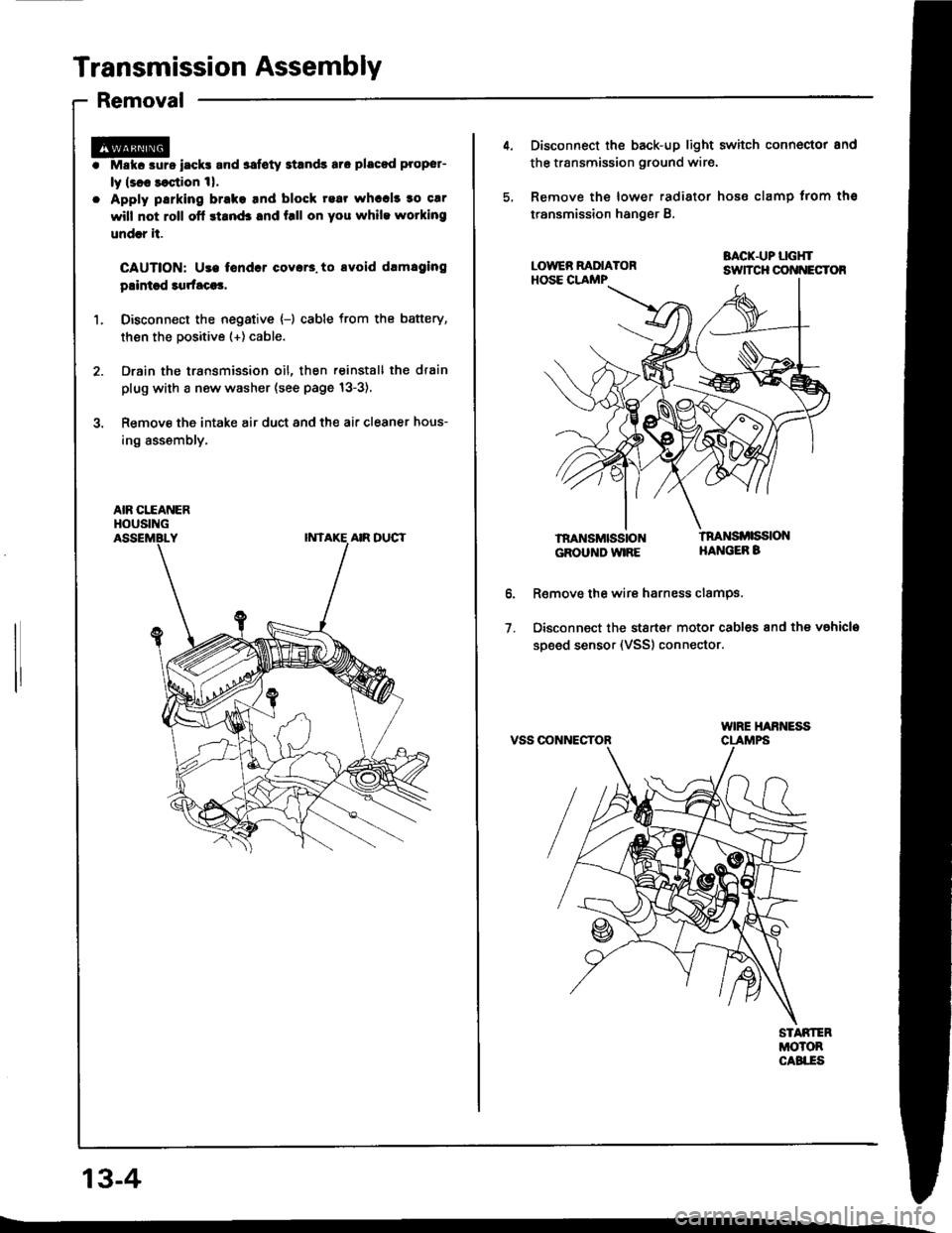
Mskc aurs iack! and safoty Etands aro placod proper-
ly lsl8 saqtion 1|.
Apply parking brake tnd block rear whccl! to car
will not roll ofl stand3 and f.ll on you while wotking
undrr it.
CAUTION: Use tondcr coyar3. to avoid drmlging
plintsd 3qrfaca3,
Disconn€ct the negative {-) cable from the battery,
then the positive (+) cable.
Drain the transmission oil, then reinstall the drain
plug with a new washer (see page 13-3),
Remove the intake air duct and the air cleaner hous-
ing assembly,
AIR CITANERHOUSING
13-4
4. Disconnect the back-up light switch connoctor and
the transmission ground wir€.
5, Remove the lower radiator hose clamp trom ths
transmission hanger B.
BACK.UP LGHTsuTcH cot{t{EcToR
lnaNsMttistoNGROUND WIRE
tnaNsi ssloNHANGEB B
o.
1.
R€move the wire harness clamPs.
Disconnect the stsrt€r motor cables and the vahicla
soeed sensor (VSS) connector.
VSS OONNECTOR
Page 347 of 1413
Removo tho clutch pip€ bracket and th€ slave cylin-
oer.
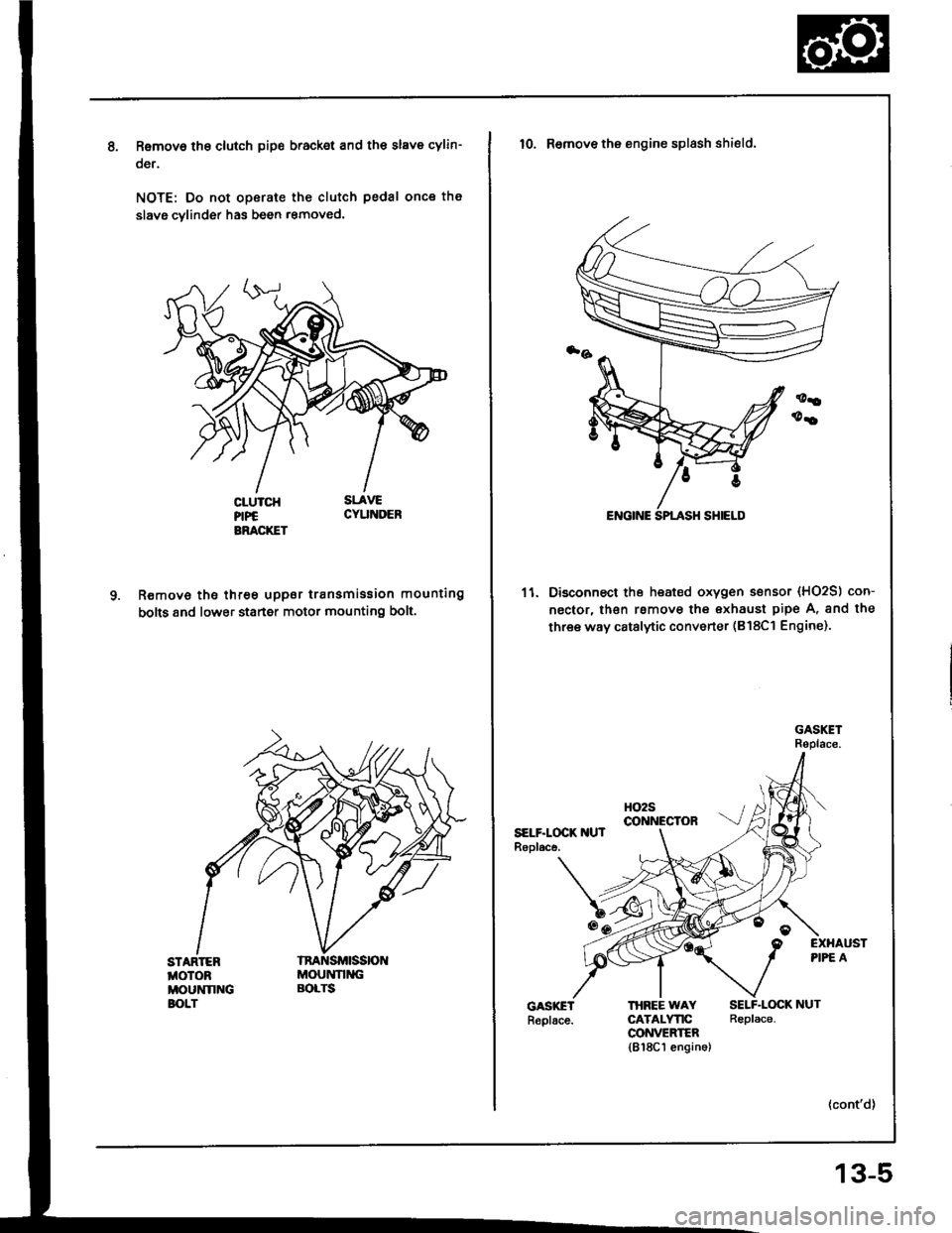
NOTE: Do not operate the clutch pedal once th€
slavg cvlinder has been r€moved.
R€move the three uppor transmission mounting
bolts 8nd lower staner motor mounting bolt.
STARTEBMOTOBMOUNNNGBOLT
MOUNNNGBOLTS
10. Remove the engine splash shield.
11. Disconnect the heated oxygen sensor (HO2S) con-
nector, lhsn rsmove the exhaust pipe A, and the
three way catalytic converter (B18Cl Engine).
HO2Sco NEctoRSELF.LOCK IIUTRopl.ce.
EXHAUSTPIPE A
THBEE WAYCATALYTICCONVEEIER1818C1 engin6)
SELF.LOCK NUTReplace.
13-5
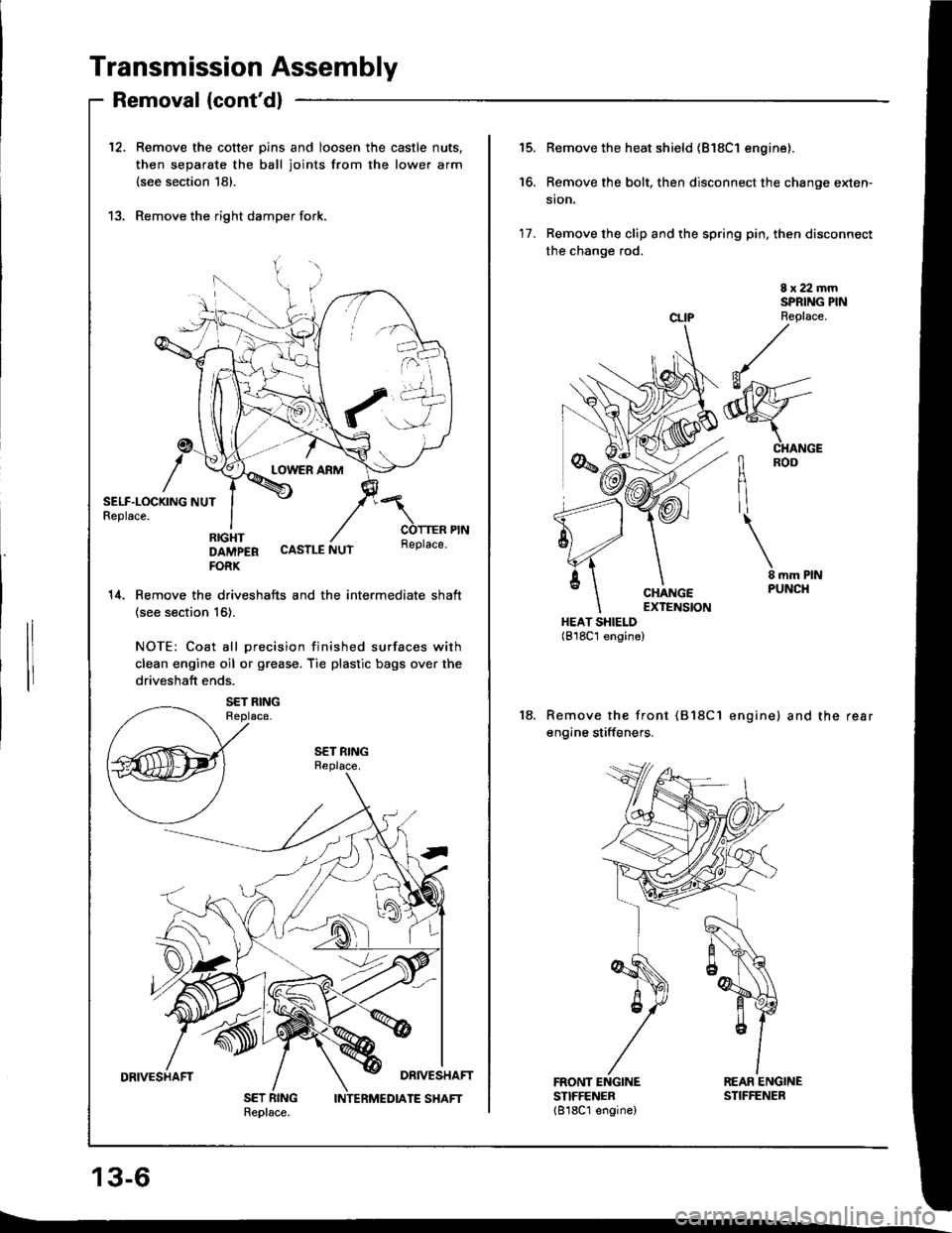
Page 348 of 1413
Page 349 of 1413
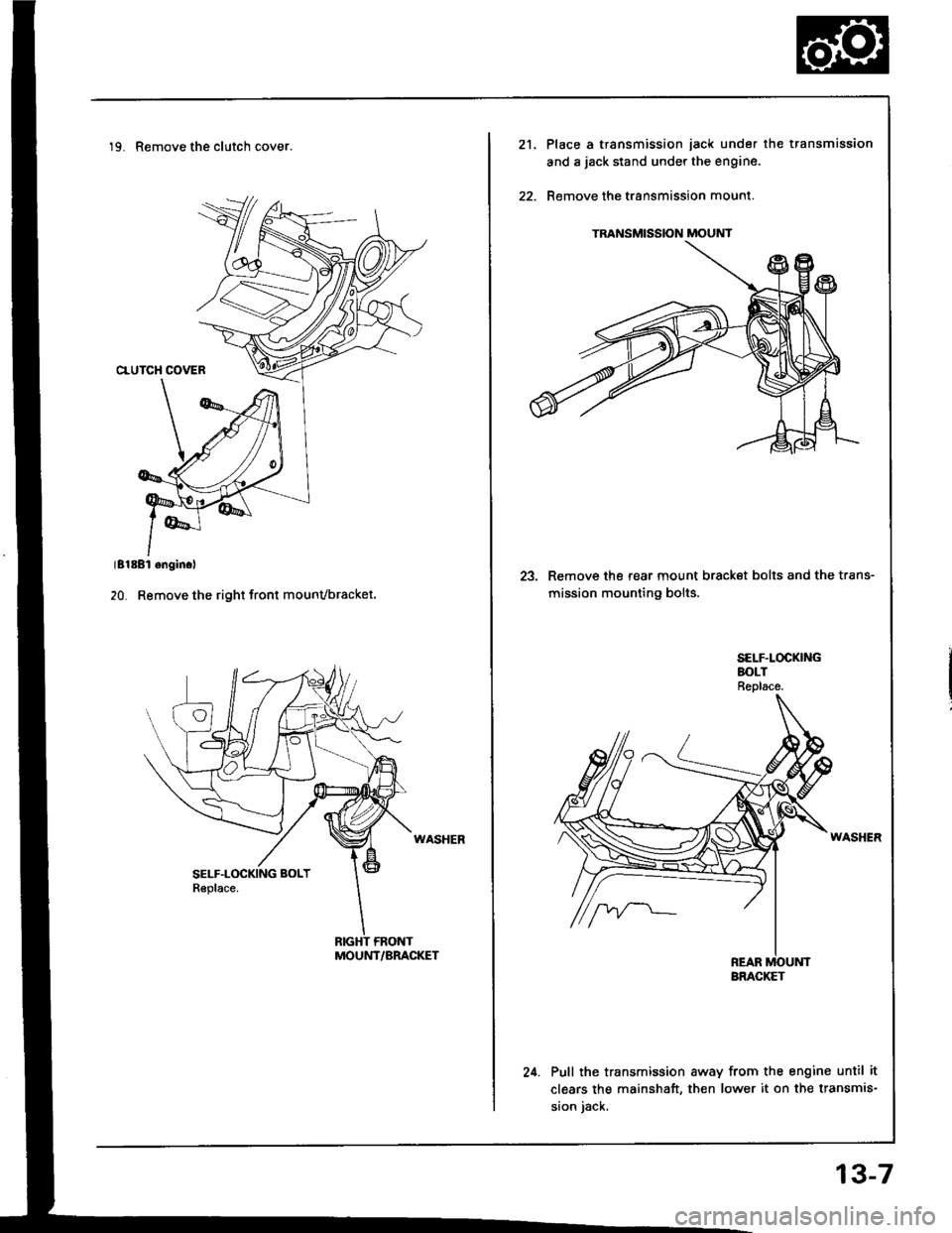
19. Remove the clutch cover.
MOUNT/BRACKET
TRANSMISSION MOUNT
21.Place a transmission iack under the transmission
and a jack stand under the engine.
Remove the transmission mount.
23. Remove the rear mount bracket bolts and the trans-
mission mounting bolts.
24. Pull the transmission away from the engine until it
clears the mainshaft, then lower it on the transmis-
sion iack.
BRACKET
13-7
Page 350 of 1413
lllustrated Index
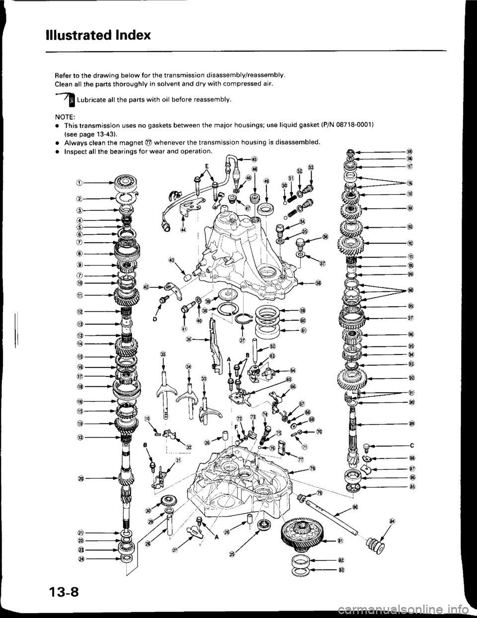
Refer to the drawing below for the transmission disassembly/reassembly.
Clean all the parts thoroughly in solvent and dry with compressed air.
I ruurlcate att the parts with oil before reassembly.
NOTE:
. This transmission uses no gaskets between the major housings; use liquid gasket (P/N 08718-0001)
{see page 13-43).
a
a
Alwavs clean the magnet @ whenever the transmission housing is disassembled.
Inspect all the bearings for wear and operation.
(9
@
@
tqqlnl^'1ult I Ej
nl
11-4fi
,\|j Uh
o
@
o
@@
@
@
(3
(,
@
@
@
a
@
@
@
@
B
tg
Y
o
@
@
@
*N
13-8
[@.--oaF5i,--@:7
Trending: coolant temperature, trunk trim, 11-52, Valve cover install, fuel, rear frame, Tp sensor
