HONDA INTEGRA 1998 4.G Workshop Manual
Manufacturer: HONDA, Model Year: 1998, Model line: INTEGRA, Model: HONDA INTEGRA 1998 4.GPages: 1681, PDF Size: 54.22 MB
Page 1001 of 1681
Troubleshooting
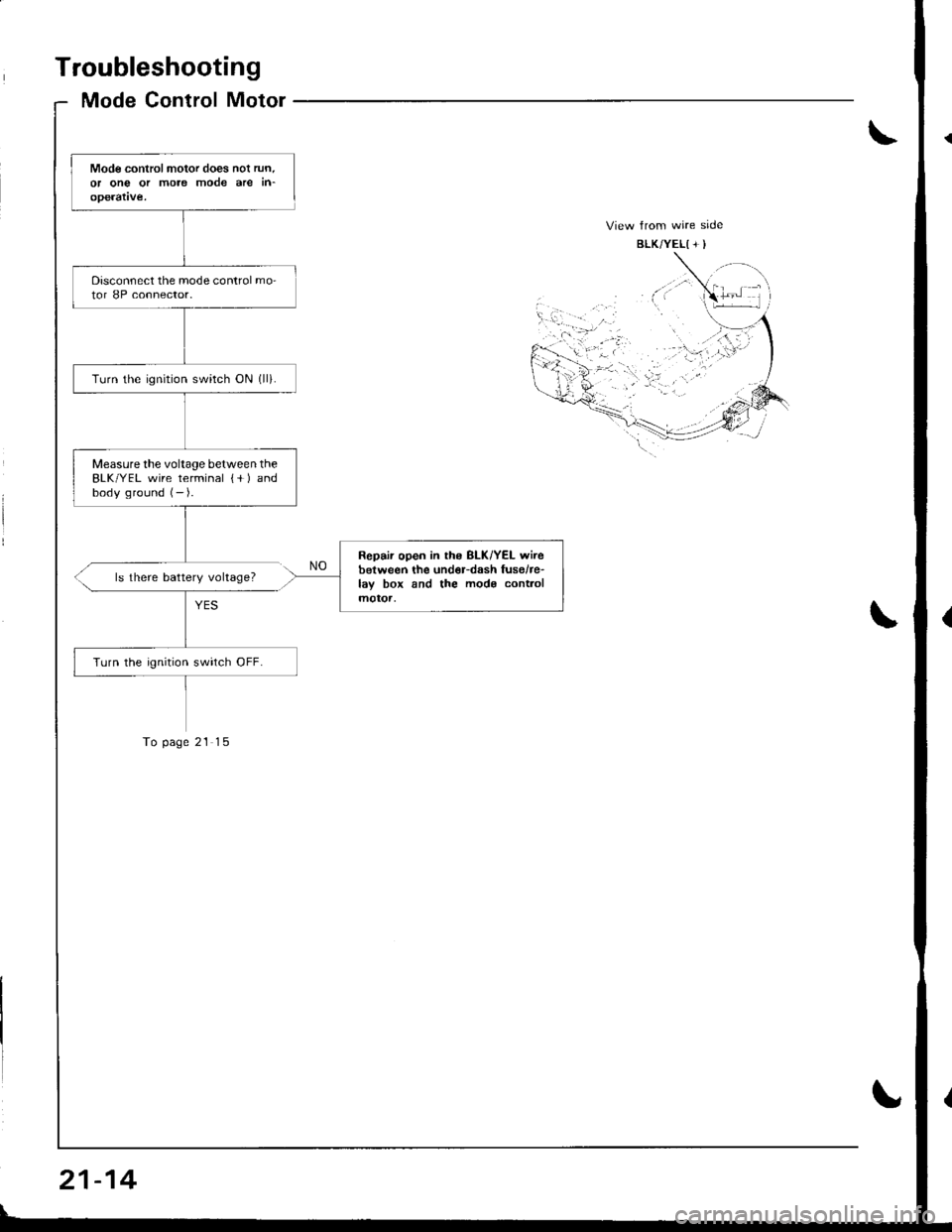
Mode Control Motor
Mode controlmotor does nol run.or ong or more mode are in-operatve.
Disconnect the mode control mo-tor 8P connector.
Turn the ignrtion switch ON (ll).
Measurethe voltage between theBLK/YEL wire terminal {+ ) andbody ground (- ).
Repair open in ths BLK/YEL wirebetween the und€r-dash fusehe-lay box and the mods cont.olmotoa,
Turn the ignition swirch OFF.
ls there battery voltage?
To page 21 15
21-14
Page 1002 of 1681
II
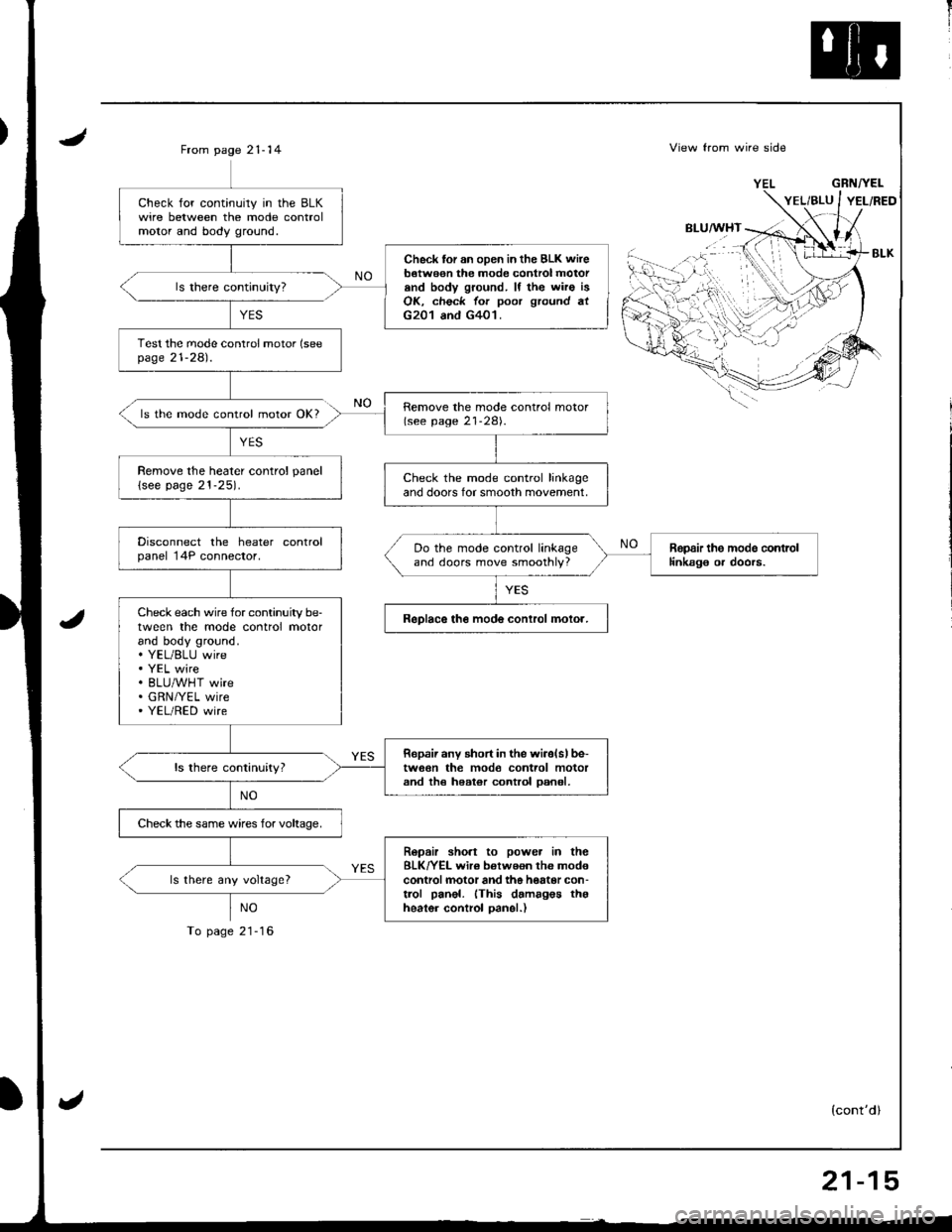
JFrom page 21- 14
ls the mode control motor OK?
YES
NO
To page 21-16
View from wire side
BLU/WHT
GRNTYEL
(cont'dl
Check for continuily in the BLKwire between the mode controlmolor and body ground.
Check tor an oDen in the BLK wireb€twe€n the mode control motorand body ground. lf the wiro isOK, check for poor ground atG201 and G401.
Test the mode conlrol motor (seepage 21-281.
Remove the mode control motor(see page 21-28).
Remove the heater control panel
lsee page 21-25).Check the mode control linkageand doors for smooth movement,
Disconnect the heater controlpanel 14P connector.Ropair the modo contrcllinkag€ or doors.Do the mode control linkageand doors move smoothly?
Check each wire for continuity be-tween the mode control motorand body ground.. YEL/BLU wire. YEL wire. BLU/WHT wire. GRN/YEL wire' YEL/RED wire
ReDlace the mode conlrol molor.
Ropaii any short in the wiiolslbe-tw6€n the mod€ control motorand th€ heater control oan6l,
Check the same wires for voltaoe,
Ropair sho.t to power in theBLK/YEL wir€ betweon the mod€controlmotor and the hottor con-trol panel. (This damagos thgheater control oanel.)
ls there any voltage?
,.i:...
''{
'rt'',-
21-15
Page 1003 of 1681
Troubleshooting
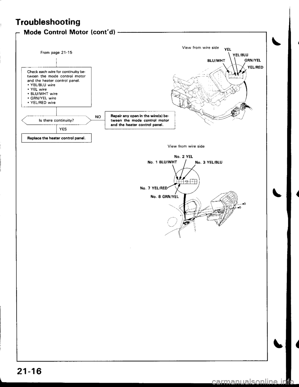
Mode Control Motor (cont'd)
From page 21-15
View lrom wire side
No. 2 YEL
No. 1 BLU,4 THTNo. 3 YEL/BLU
No. 7
No. I GRN/YEL
Check each wire for continuity be-tween the mode control motorand the hoater control panel.. YEL/BLU wire. YEL wire. BLUMHT wire. GRN/YEL wire. YEL/RED wire
R6pair any open in th€ wirels) be-tween the modo control motoiand the heater control oan€|.
Replace the hsatar control panol.
View from wire side yEL
,,'; -(('
1iu'.'''.. 1
,,...:N.V
'i
21-16
Page 1004 of 1681
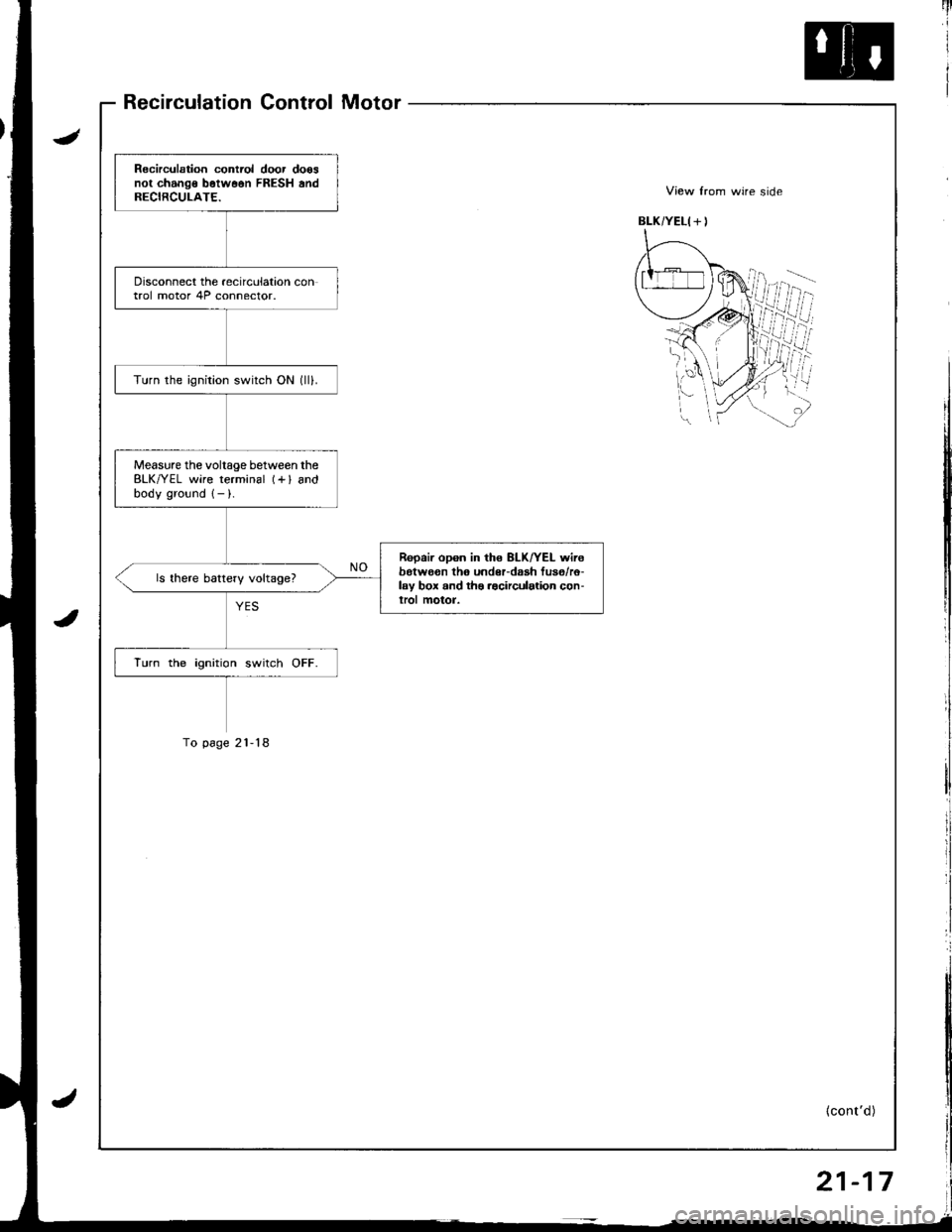
Recirculation Control Motor
Recirculation contiol door doosnot change b6tw66n FRESH andRECIRCULATE.
Disconnect the recirculation control motor 4P connector.
Turn the ignition switch ON (lll.
Measure the voltage between theBLK/YEL wire terminal (+l andbodv ground 1- ).
Repair opon in the 8LK/YEL wirebotwo€n th6 undeFdaah fus6/r6-lay box and ths .acirculation con-lrol motor.
ls there battery voltage?
lurn the ignition switch OFF.
To p6ge 21-18
{cont'd)
21-17
Page 1005 of 1681
Troubleshooting
Recirculation Control Motor (cont'dl
\
From page 21-17
Remove the recirculation controlmotor (see page 21 291.
Check the recirculation controllinkage and door for smooth
Remove the heater control panel(see page 21-25).Do the recirculationcontrol linkage and doormove smoothly?
Rspair the recirculationcontrol linkagg o. door.
Disconnect the heater controlpanel 14P connector.
Check for continuity in theGRN/WHT and GRN/RED wiresbetween the recirculation controlmotor and bodv ground.
Reoair short in the GRN/WHTand/or GRN/REO wire(s) betweentho recirculation control motorand the heaioi control Dan6l.
Check the same wires for voltage.
Repair short to power in thoBLK/YEL wire between the recir-culation control motor and theheater control oanel. lThisdamages the heater controlDan€|.)
ls there 6ny voltage?
Check for continuity in theGRN/WHT and GRN/RED wiresbetween the recirculation controlmotor and the heater controlpanel.
Bepair open in the GRN/WHTand/or GRN/RED wirelsl betw6enthe recirculation control motorand the heator control Dan€|.
Replace the h6alor control panel.
Test the recarculation control mo-tor (see page 21 2g).
ls the recirculation controlmotor OK?
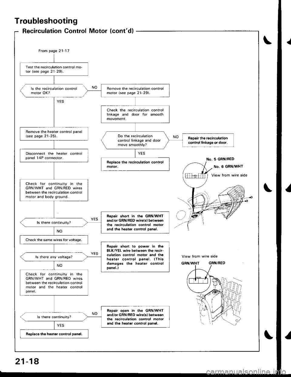
No. 5 GRN/RED
View from wire side
21-18
Page 1006 of 1681
1i
II
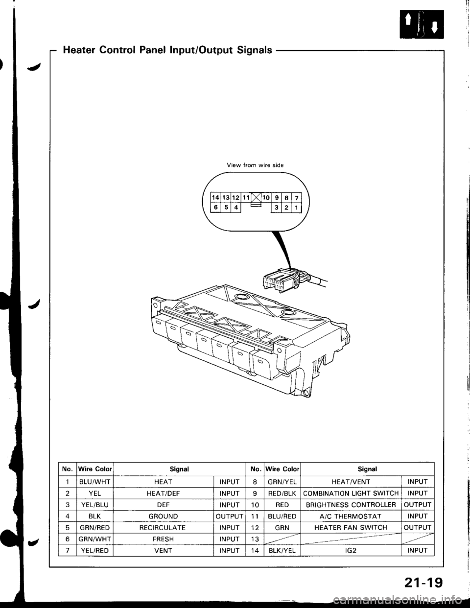
Heater Control Panel Input/Output Signals
No.Wire ColorSignalNo.Wile ColorSignal
BLU/WHTHEATINPUT8GRN/YELHEAT/VENTINPUT
2YELHEATiDEFINPUTqRED/BLKCOMBINATION LIGHT SWICHINPUT
3YEL/BLUDEFINPUT10REDBRIGHTNESS CONTROLLEROUTPUT
BLKGROUNDOUTPUT11BLU/REDA/C THERMOSTATINPUT
5GRN/REDRECIRCULATEINPUTGRNHEATER FAN SWITCHOUTPUT
6GRN/WHTFRESHINPUT
7YEL/REDVENTINPUT14BLK/YELINPUT
21-19
Page 1007 of 1681
Blower Unit
Replacement
NOTEr The blower motor, recirculation control motor
and blower resistor can be replaced without removjng
the blower unit (see page 21-21).
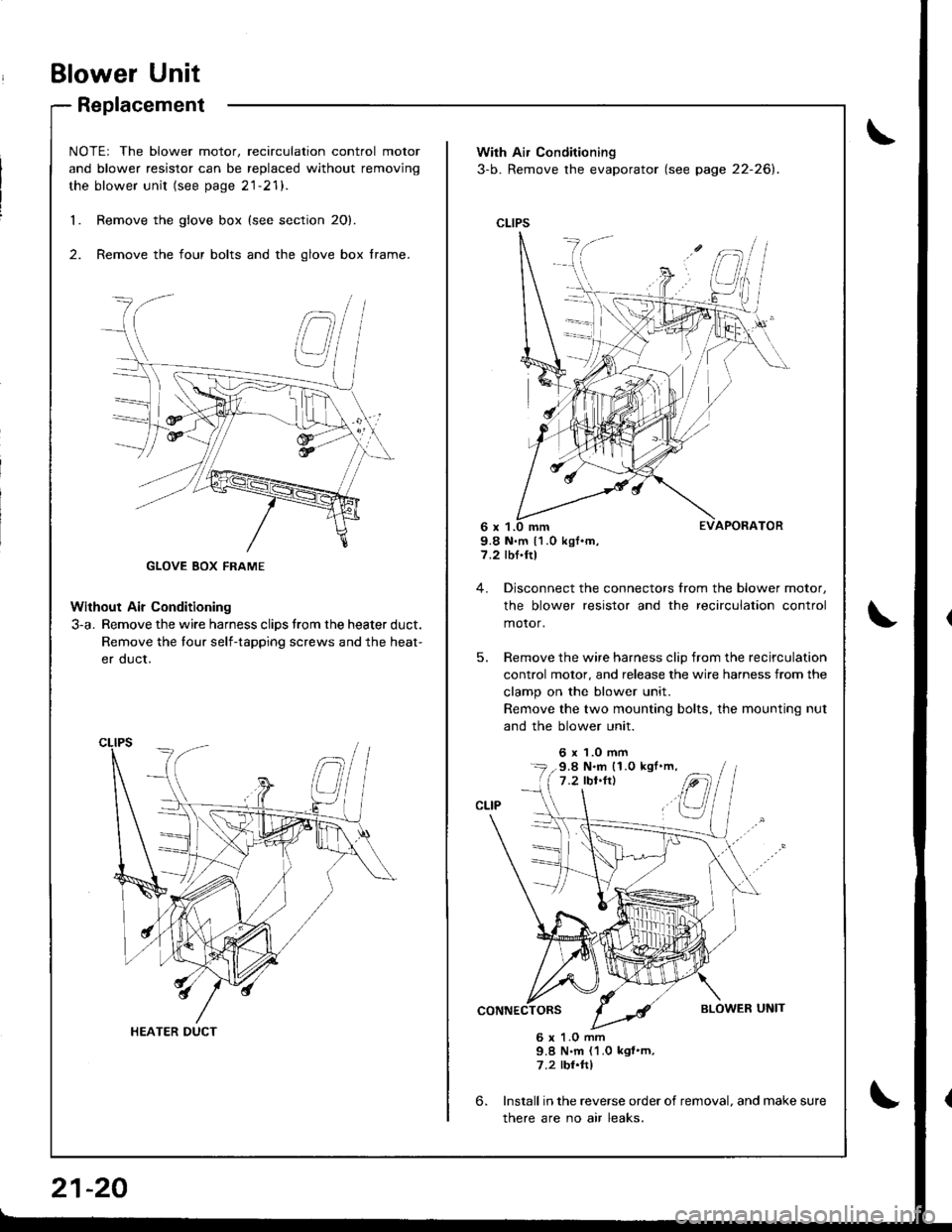
Remove the glove box {see section 20}.
Remove the four bolts and the glove box frame.
Without Air Conditioning
3-a. Remove the wire harness clips trom the heater duct.
Remove the tour self-tapping screws and the heat-
er duct.
1.
2.
HEATER DUCT
21-20
With Air Conditioning
3-b. Remove the evaporator (see page 22-26).
CLIPS
9.8 N.m 11.0 kgf.m,7.2 rbf.ftl
4. Disconnect the connectors from the blower motor,
the blower resistor and the recirculation control
motor,
5. Remove the wire harness clip from the recirculation
control motor, and release the wire harness from the
clamp on the blower unit.
Remove the two mounting bolts, the mounting nut
and the blower unit.
6 x 1.0 mm
6.
6 x 1.O mm9.8 N.m (1.0 kgf'm,7.2 rbr.ftl
Install in the reverse order of removal. and make sure
there are no air leaks.
9.8 N.m (1.0 kgl'm,
Page 1008 of 1681
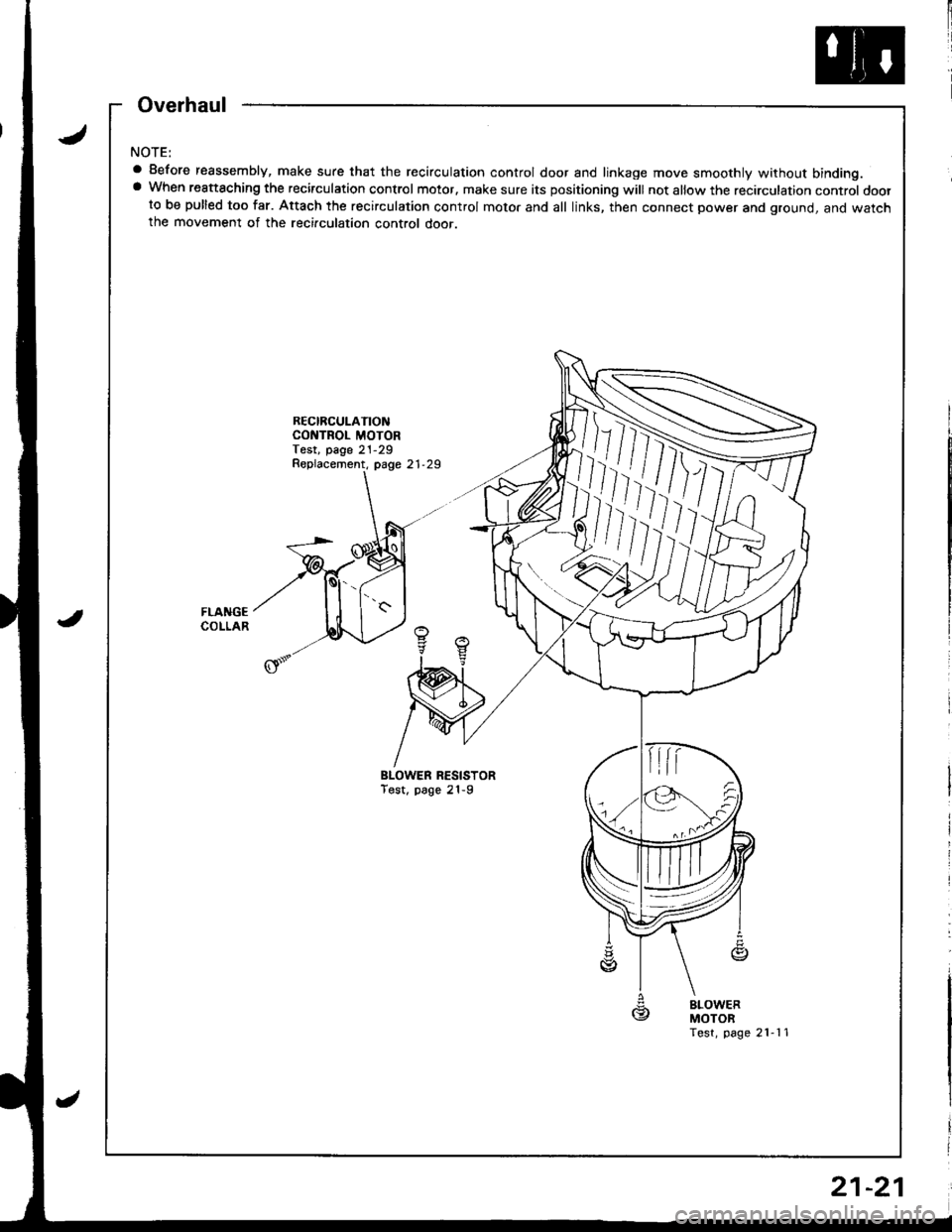
NOTE:
a Before reassembly, make sure that the recirculation control door and linkage move smoothly without binding.a When reattaching the recirculation control motor. make sure its positioning will not allow the recirculation control doorto be pulled too far. Attach the recirculation control motor and all links, then connect power and ground, and watchthe movement of the recirculation control door.
RECIRCULATIONCONTROL MOTORTest, page 21-29
BLOWER RESISTORTost, page 21-9
gBLOWERMOTORTest, page 21-11
Replacement, page 21-29
,/],�
Overhaul
21-21
Page 1009 of 1681
Heater Unit
Replacement
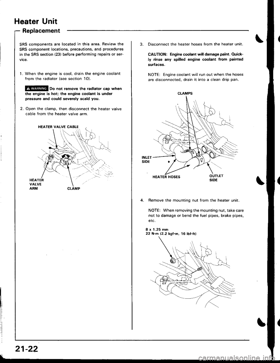
SRS components are located in this area. Review the
SRS component locatio.s, precautions, and procedures
in the SRS section (23) before performing repairs or ser-
vtce.
1. When the engine is cool, drain the engine coolant
from the radiator (see section 1O).
@ oo not remove the radiator cap when
the engine is hot; the engine coolant is undol
prsssure and could sevdely scald you.
2. Ooen the clamD, then disconnect the heater valve
cable from the heater valve arm.
HEATER VALVE CABI-E
I
i
21-22
3. Disconnect the heater hoses lrom the heater unit.
CAUTION: Engine coolant will damaga paint. Ouick-
ly rinse any spilled engine coolant from painted
sudaces.
NOTE: Engine coolant will run out when the hoses
are disconnected, drain it into a clean drip pan.
4. Remove the mounting nut from the heater unit.
NOTE: When removing the mounting nut, take care
not to damage or bend the fuel pipes, brake pipes,
etc.
8 x 1.25 mm22 N'llt. 12.2 kgl'm, 16 lbl.tl)
CLAMPS
HEATER HOSES
Page 1010 of 1681
.J
5.
6.
7.
8.
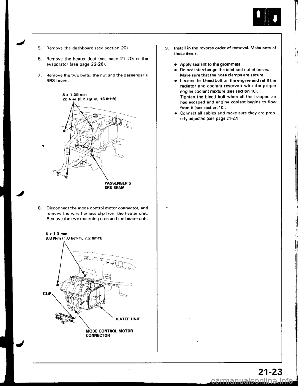
Remove the dashboard (see section 2O).
Remove the heater duct (see page 21 20) or the
evaporator lsee page 22-261.
Remove the two bolts, the nut and the passenger's
SRS beam.
PASSENGER'SSRS BEAM
Disconnect the mode control motor connector. and
remove the wire harness clip from the heater unit.
Remove the two mounting nuts and the heater unit.
6 x 1.0 mm9.8 N.m (1.0 kgf.m, 7.2 lbf.ftl
I r 1.25 mm22 N.m 12.2 kgf.m, 16 lbf'ft)
Il
I
I
lnstall in the reverse order of removal. Make note of
these items:
. Apply sealant to the grommets
. Do not interchange the inlet and outlet hoses.
Make sure that the hose clamps are secure.
. Loosen the bleed bolt on the engine and refill the
radiator and coolant reservoir with the proper
engine coolant minure (see section 10).
Tighten the bleed bolt when all the trapped air
has escaped and engine coolant begins to flow
from it (see section 10).
. Connect all cables and make sure they are prop-
erly adjusted (see page 2'l-271.
;!
i
21-23