HONDA INTEGRA 1998 4.G Workshop Manual
INTEGRA 1998 4.G
HONDA
HONDA
https://www.carmanualsonline.info/img/13/6069/w960_6069-0.png
HONDA INTEGRA 1998 4.G Workshop Manual
Trending: Photo c503, buttons, child lock, seat memory, air bleeding, maintenance, oil level
Page 991 of 1681
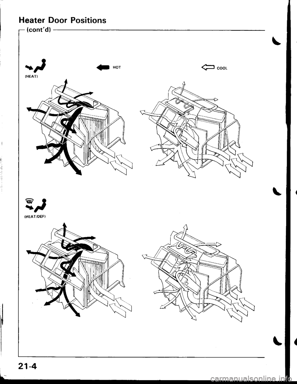
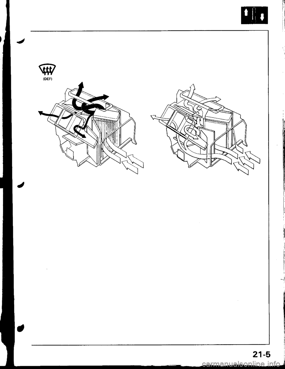
Heater Door Positions
(cont'd)
fr seel
21-4
Page 992 of 1681
Page 993 of 1681
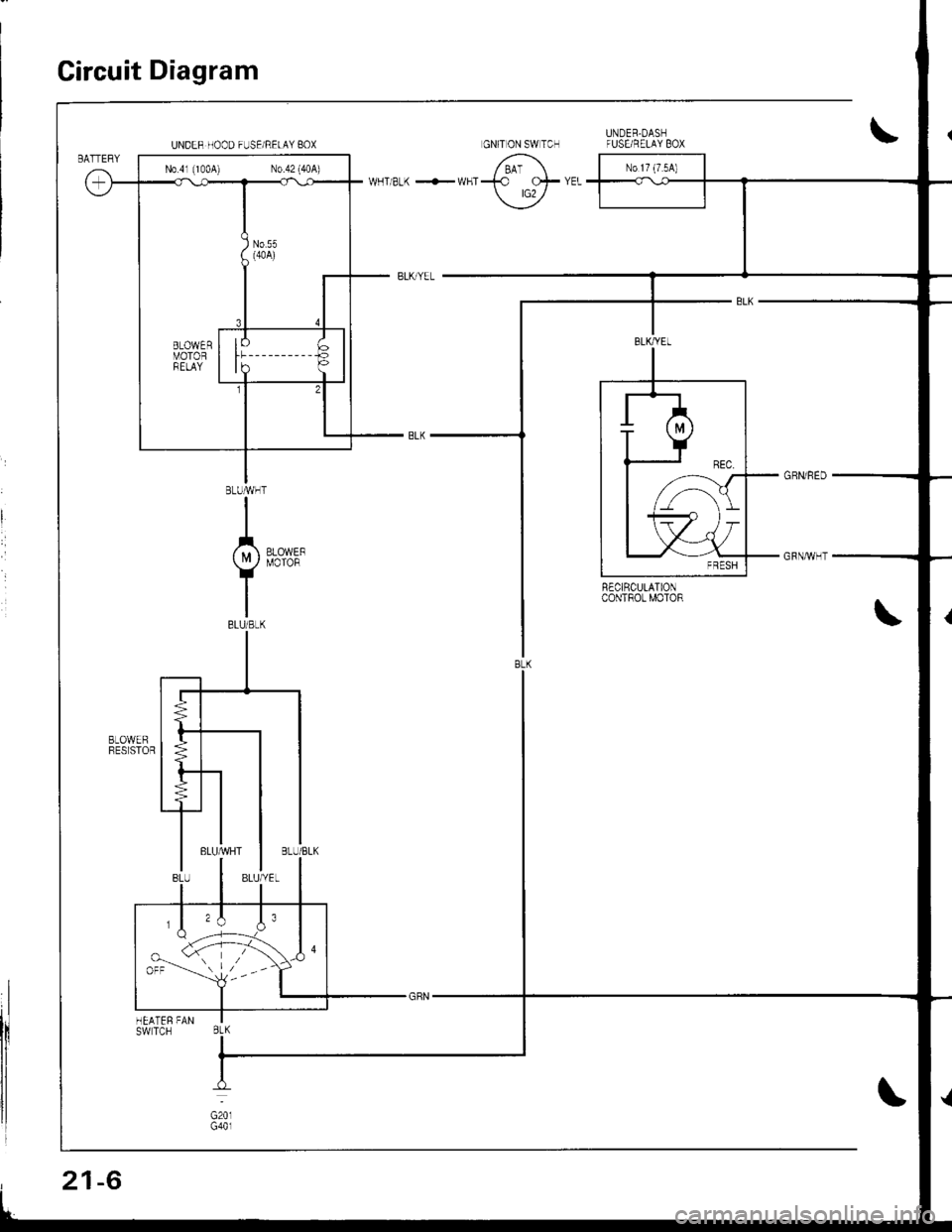
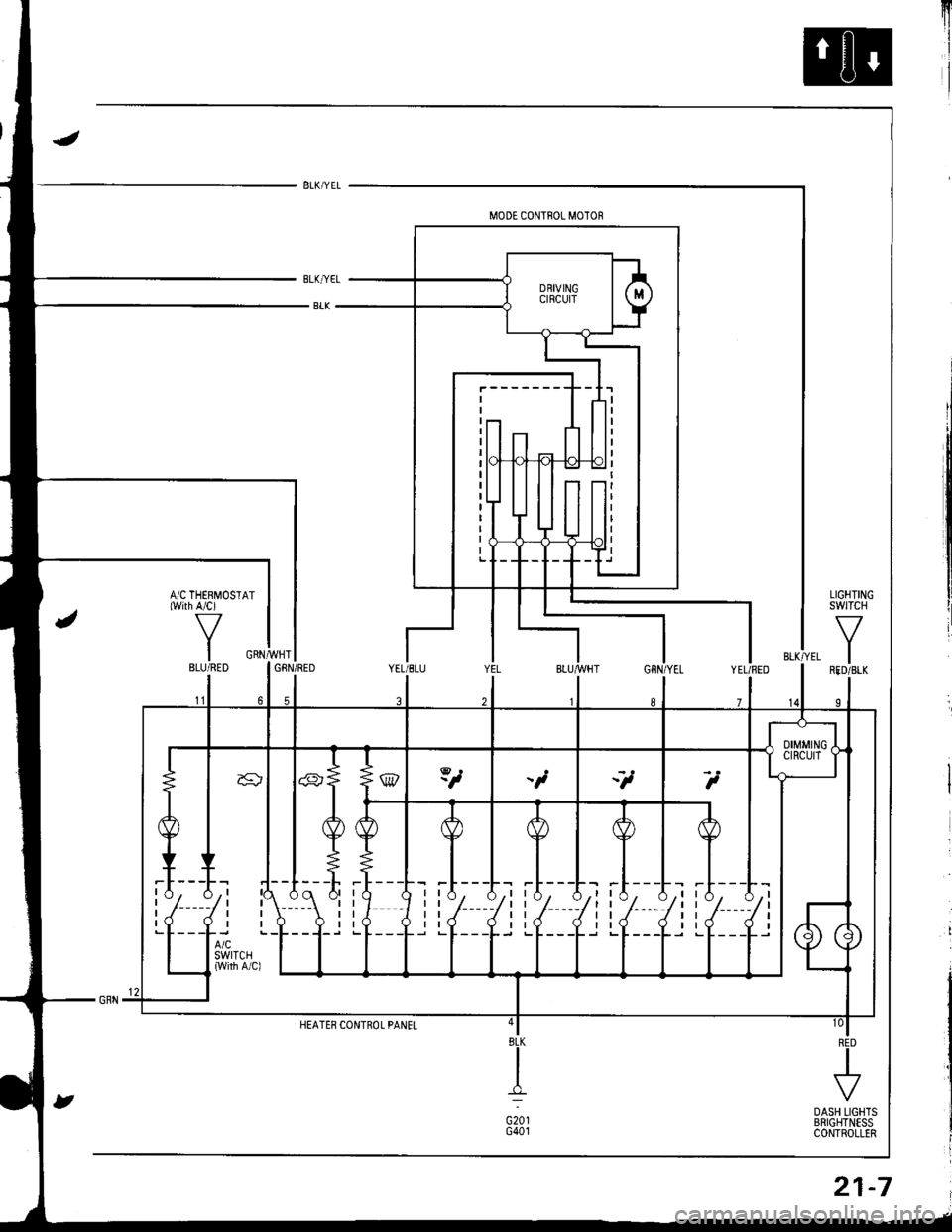
Circuit Diagram
R€CIRCULATIONcoNTROt MOTOR
UNDER HOOD FUSE/RELAY BOX
N0.41 (1004) N0.42 (40A)
,,\J.orr --'-- l,--
BtK
21-6
Page 994 of 1681
I
A/C THERMOST{with A/ci
IIBLU/RED
RED
I
.t
DASH LIGHTSBRIGHTNESSCONTROLLER
8LK
_tr:
G20tG40t
I r{1, A,r rA, A.r rA, A,t tA_ A_l| | / -/t t-/ -/t t-/ -/r t-/ -/l
ttJ ,Itt,l Jtt-l ,lttl JlI rV V I rV V trv V I tV q) |
21-7
Page 995 of 1681
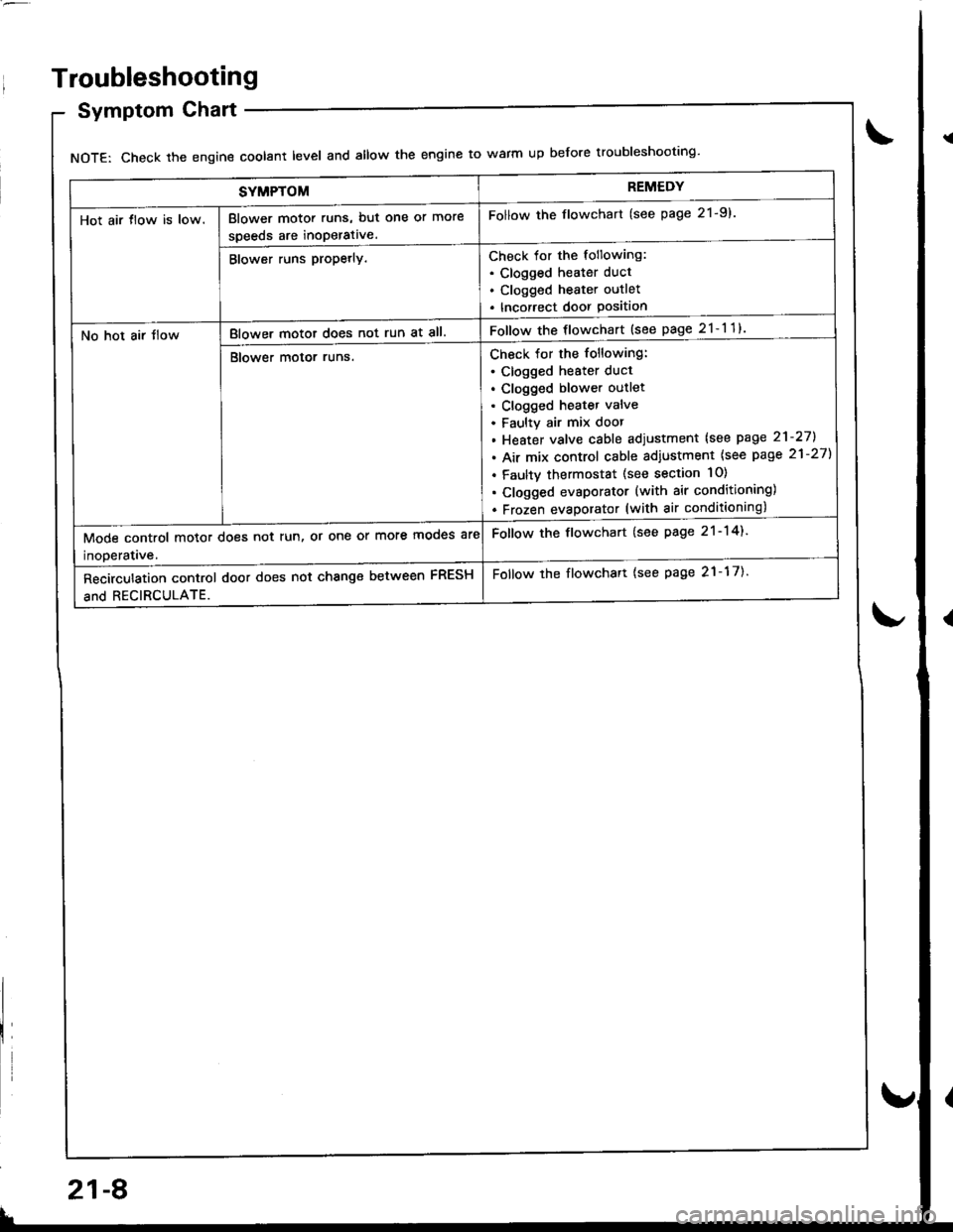
SYMPTOMREMEDY
Hot air tlow is low.Blower motor runs, but one or more
speeds are inoperative.
Follow the flowchart (see page 21-9).
Blower runs propetly.Check for the following:. Clogged heater duct
. Clogged heater outlet
. Incorrect door Position
No hot air tlowBlower motor does not run at all.Follow the flowchart {see page 21-11}
Blower motor runs.Check for the following:
. clogged heater duct
. Clogged blower outlet. Clogged heatet valve
. Faultv air mix door
. Heater valve cable adjustment lsee page 21-27].
. Air mix control cable adiustment {see page 21-27)
. Faulty thermostat (see section 10)
. Clogged evsporator (with air conditioning)
. Frozen evaDorator (with air conditioning)
Mode control motor does not run, or one or more mooes are
inoDeratave.
Follow the flowchart (see page 21-14).
Recirculation control door does not change between FRESH
and RECIRCULATE.
Follow the flowchart {see page 21-17).
Troubleshooting
Symptom Chart
NOTE: Check the engin€ coolant level and allow the engine to warm up before troubleshooting'
21-8
v
Page 996 of 1681
qrt
View from wire side
BLU/BLKBLU/WHT
1
To page 21- 1O
ii!
i'l! |
f
'tr
t
!
I
!I
tl
\\
BLU/YEL
l'r
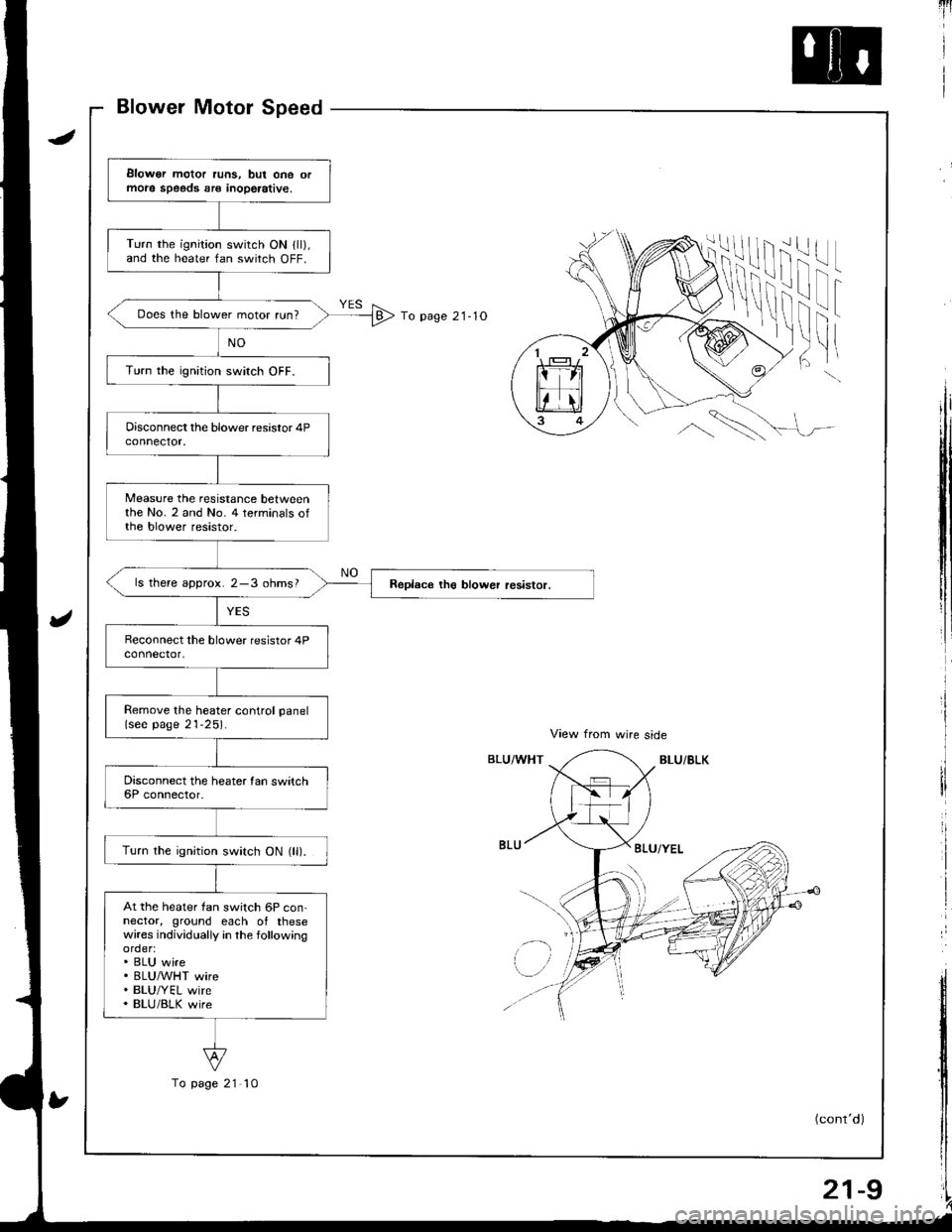
Elowor motor runs, but one ormole speeds sr€ inoperative,
Turn the ignition switch ON lll),and the heater fan switch OFF.
Does the blower motor run?
Turn the ignition switch OFF.
Measure the resistance betweenthe No. 2 and No. 4 terminals ofthe blower resistor.
ls there approx. 2-3 ohms?
Remove the heater control panel(see page 21-25).
Turn the ignition switch ON (ll).
At the heater fan switch 6P con-nector, ground each of thesewires individually in the followingorder:. BLU wire. BLUMHT wire. BLU/YEL wire. BLU/BLK wire
To page 21 10
(cont'd)
21-9
Page 997 of 1681
Troubleshooting
Blower Motor Speed (cont'dl
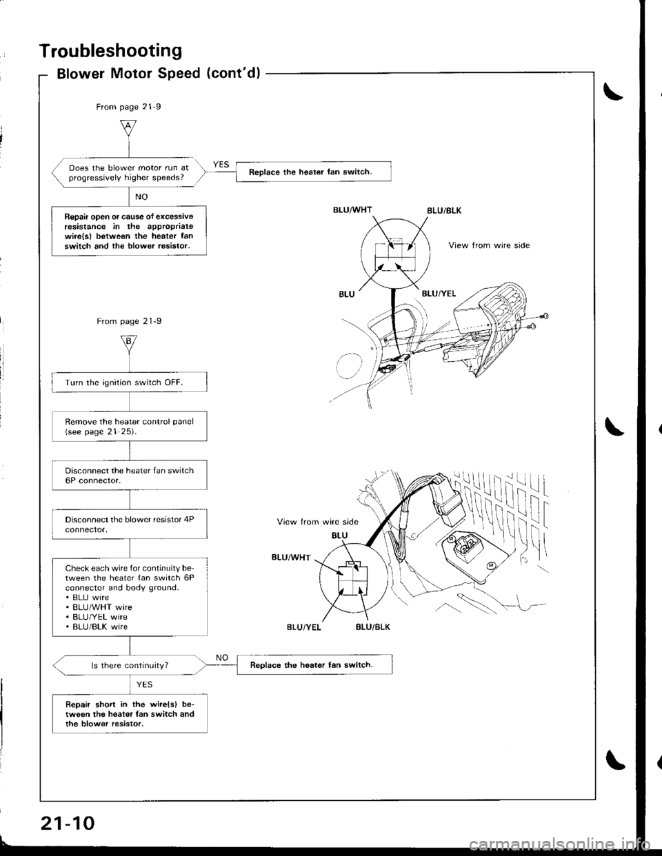
From page 21-9
Does the blower motor run atprogressively higher speeds?Reolace the heat€r tan switch.
Repair open or cause of excessiveresistance in the approprialewi.e{s) betweon the heater fanswitch and the blower resistor.View from wire side
From page 21-9
View trom wire side
BLU
ilif
fril t
)ltBLU/WHT
ls there continuity?
BLU/BLK
BLU
' lz-
Turn the ignition switch OFF.
Remove the heater conlrol panel(see page 21 25).
Check each wire for continuity be-tween the heater fan switch 6Pconnector and body ground.. ELIJ wire. BLU/WHT wire. BLU/YEL wire. BLU/BLK wire
Replace the heat6r fan switch.
Bepair short in the wire(sl be-tween the heater fan switch andthe blow€r resistor.
If
\!,\
BLU/BLK
21-10
Page 998 of 1681
Blower Motor
View from wire side
View from wire slde
BLOWER MOTOR RELAY IP SOCKET
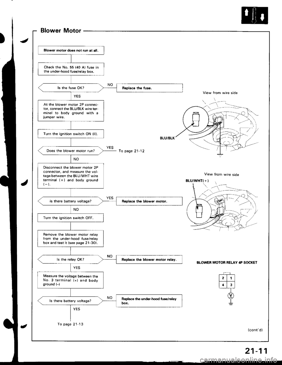
Blower motoa does not aun at all.
check the No. 55 {40 A} fuse inthe undeFhood fuse/relay box.
At the blower motor 2P connec-tor, connecl the BLU/8LK wire terminal to body ground with a
iumper wire.
Turn the ignition switch ON {ll).
Does the blower motor run?
Disconnect the blower motor 2Pconnector, and measure the vol-tage between the BLU/vVHT wireterminal (+) and body ground(-).
ls there battery vokagel
Turn the ignition switch OFF.
Rernove the blower motor relayfrom the under-hood fuse/relaybox and test it (see page 2l-30).
Roplsco tho blower motor .olsy.
Measure the voltage between thoNo. 3 terminal (+) and bodyground (-)
ls there battery voltage?
To page 21- 12
To page 21 13
rD
(cont'd)
Page 999 of 1681
Troubleshooting
Blower Motor (cont'd)
From page 21-11\View from wire side
8LU/BLK( + I
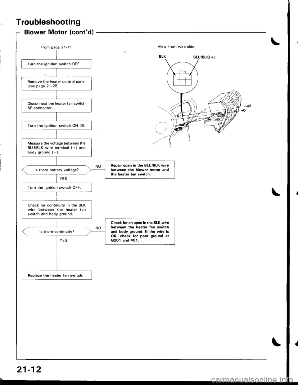
Turn the ignition switch OFF.
Remove the heater control panel(see page 21-25).
Turn the ignition switch ON lll).
Measure the voltage between theBLU/BLK wire terminal {+) andbody ground (- ).
Repair open in the BLU/Bl-K wir6between the blowea motor andthe hoster lsn switch.ls there battery voltage?
Turn the ignition swirch OFF.
Check for continuity in the BLKwire between the heater fanswitch and body ground.
Check fo. an oDen in th6 8LK wirebotwo€n th€ haat€r tan switchand body ground. ll th6 whe isOK. check tor poor ground atG201 and 401.
Rsplac€ the heat€r fan switch.
ls there continuity?
Page 1000 of 1681
From page 21-11
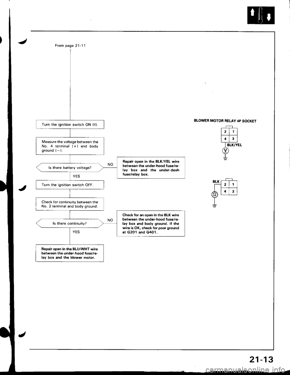
BLOWER MOTOR RELAY /rp SOCKETTurn the ignition switch ON {ll).
Measure the voltage between theNo. 4 terminal (-f ) and bodyground (- ).
Repair open in the BLK/YEL wirebetweon tho under-hood tuse/r€-lav box and th€ und€r-drshtuse/relav box.
ls there battery voltage?
Turn the ignition swrtch OFF.
Check for continuity between theNo. 2 terminal and body ground.
Check for an oDen in the BLK wir€belween the undor-hood fuso/re-lay box and body ground. It thewire is OK, check forpoor groundat G201 and G4O1.
Ropair open in the BLU/WHT wirebetween the undor-hood fuse/re-lav box and the blow€r motor.
21
4
Trending: transmission oil, engine, tires, fuse box, check transmission fluid, wheel size, charging
