HONDA INTEGRA 1998 4.G Workshop Manual
Manufacturer: HONDA, Model Year: 1998, Model line: INTEGRA, Model: HONDA INTEGRA 1998 4.GPages: 1681, PDF Size: 54.22 MB
Page 971 of 1681
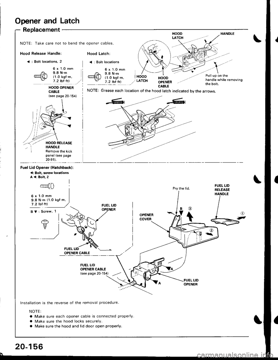
Opener and Latch
Replacement
Hood Release Handle:
< : Bolt locations, 2
HANDLE
NOTE: Take care not to bend the opener cables.
Hood Latch:
< | Bolt locations
6 x 1.0 mm9.8 N.m(1 .0 kgf m,7 .2 thl ltlHOODOPENERCAELE
Pull up on thehandle while removingthe bolt.HOOD OPENERCABLE(see page 20-154)
NOTE: Grease each location ofthe hood latch indicated bvthe arrows.
Pry the lid.
OPENERCOVER
Remove the kickpanel (see page20-9r ).
Fuel Lid Opener {Hstchbackl:
<: Bolt. screw locdionsA <: Boh.2
6x1.0mm9.8 N m 11.0 kgf m,
7 .2 lbl lrl
BV: Screw, 1
FUEL LIDRELEASEHANDLE
@
Ib
t
lnstallation is the reverse of the removal procedure.
NOTE:
a Make sure each opener cable is connected properly.
a Make sure the hood locks securely.
a Make sure the hood and lid door open properly.
FUEL LIDOPENER CAELE(see page 20-154)
20-156
Page 972 of 1681
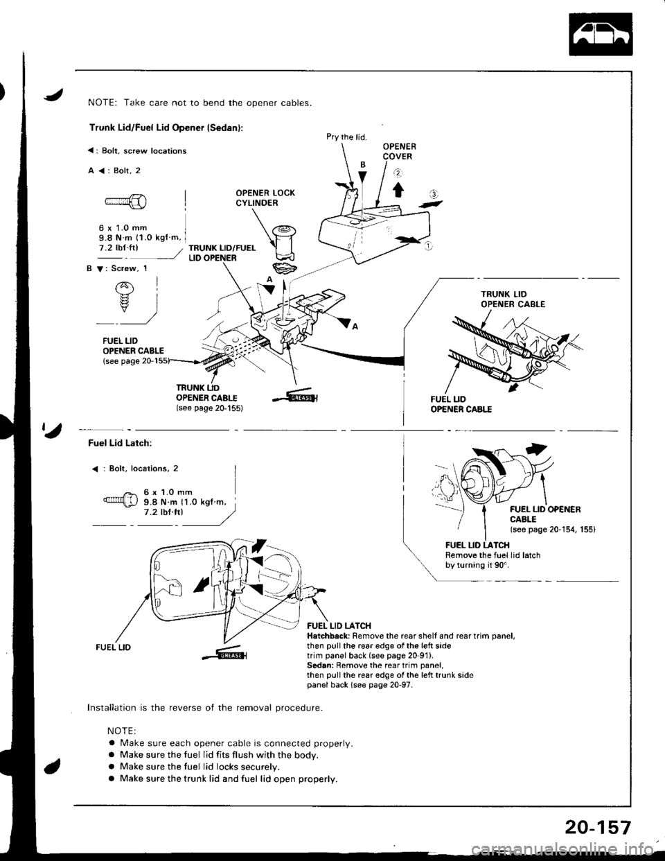
NOTE: Take care not to bend the opener cables.
Trunk Lid/Fuel Lid Opener lSedan):
<: Bolt, screw locations
A<:Bolt,2
OPENER LOCKCYLINDER
6 x 1.0 mm9.8 N m 11.o kgf m,
TRUNK LID/FUELLID
OPENER CABLE{see page 20-1
OPENERCOVER
z
tat-
7.2 tbt.trl /
B V: Screw, 1
rql.b.rz
rs? IY)
FUEL LID
TRUNK UDOPENER CABI.I(see page 20'155)
Pry the lid.
ta
Fuel Lid Latch:
: Bolt, locaiions, 2
6 x 1.O mm9.8 N.m 11.0 kgt m,7.2 tbl.trl J/)
FUEL LID OPEiIERCABLE(see page 20-154, 155)
FUEL LID LATCHRemove the fuel lid latchby turning it 90'.
FUEL LIO
Installation is the reverse of the removal procedure.
NOTEI
a Make sure each opener cable is connected properly.
a Make sure the fuel lid fits flush with the body.
a Make sure the tuel lid locks securely.
a Make sure the trunk lid and fuel lid open properly.
FUEL LID LATCHHatchbsck: Remove the rear shell and rear trim oanel,then pull the 196r edge of the left sidetrim panel back (see page 20-91).Sedan: Remove the rear trim panel,then pull the rear edge ol the left trunk sidepanel back (s€e page 20-97.
20-157
Page 973 of 1681
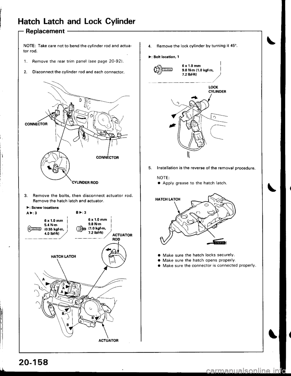
Hatch Latch and Lock Cylinder
Replacement
NOTE: Take care not to bend the cylinder rod and actua-
tor rod.
1. Remove the rear trim panel (see page 20-921.
2. Disconnect the cylinder rod and each connector.
CONNECTOR
3. Remove the bolts. then disconnect actuator rod.
Remove the hatch latch and actuator.
>: Screw loc6tion3
A>:3I >:3
ACTUATOR
20-158
4. Remove the lock cylinder by turning it 45".
>: Bolt location, 1
6x1.omm I9.8 N.m 11,0 kst m, il.ztb$ft| .)
lt: /
LOCKCYLINDEB
Installation is the reverse of the removal procedure.
NOTE:
a Apply grease to the hatch latch
a
a
a
Make sure the hatch locks securely.
Make sure the hatch opens properly.
N4ake sure the connector is connected properlV.
Page 974 of 1681
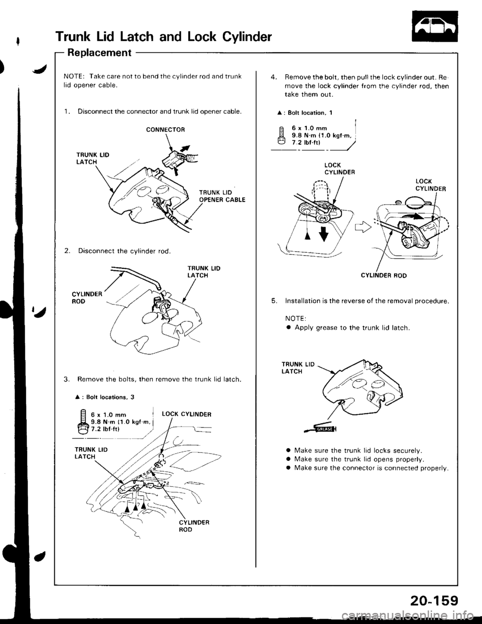
Trunk Lid Latch and Lock Cylinder
Replacement
JNOTE: Take care not to bend the cylinder rod and trunk
lid opener cable.
1. Disconnect the connector and trunk lid opener cable.
4. Remove the bolt, then pull the lock cylinder out. Re
move the lock cylinder {rom the cylinder rod, then
take them out.
: Bolt location, 1
CONNECIOR
LOCKCYLINDER
r>'
2. Disconnect the cylinder rod.
CYLINDERROD
CYLINOER ROD
5. lnstallation is the reverse of the removal procedure.
NOTE:
a Apply grease to the trunk lid latch.
Remove the bolts, then remove the trunk lid
: Boli locations, 3
TRUNK LIDLATCH
3.latch.
6x1.0mm ILOCK CYLINDER
9.8 N.m 11.0 kgf m, I
:t"r': -/
a
a
a
Make sure the trunk lid locks securely.
N/ake sure the trunk lid opens properly.
Make sure the connector is connected properly.
20-159
Page 975 of 1681
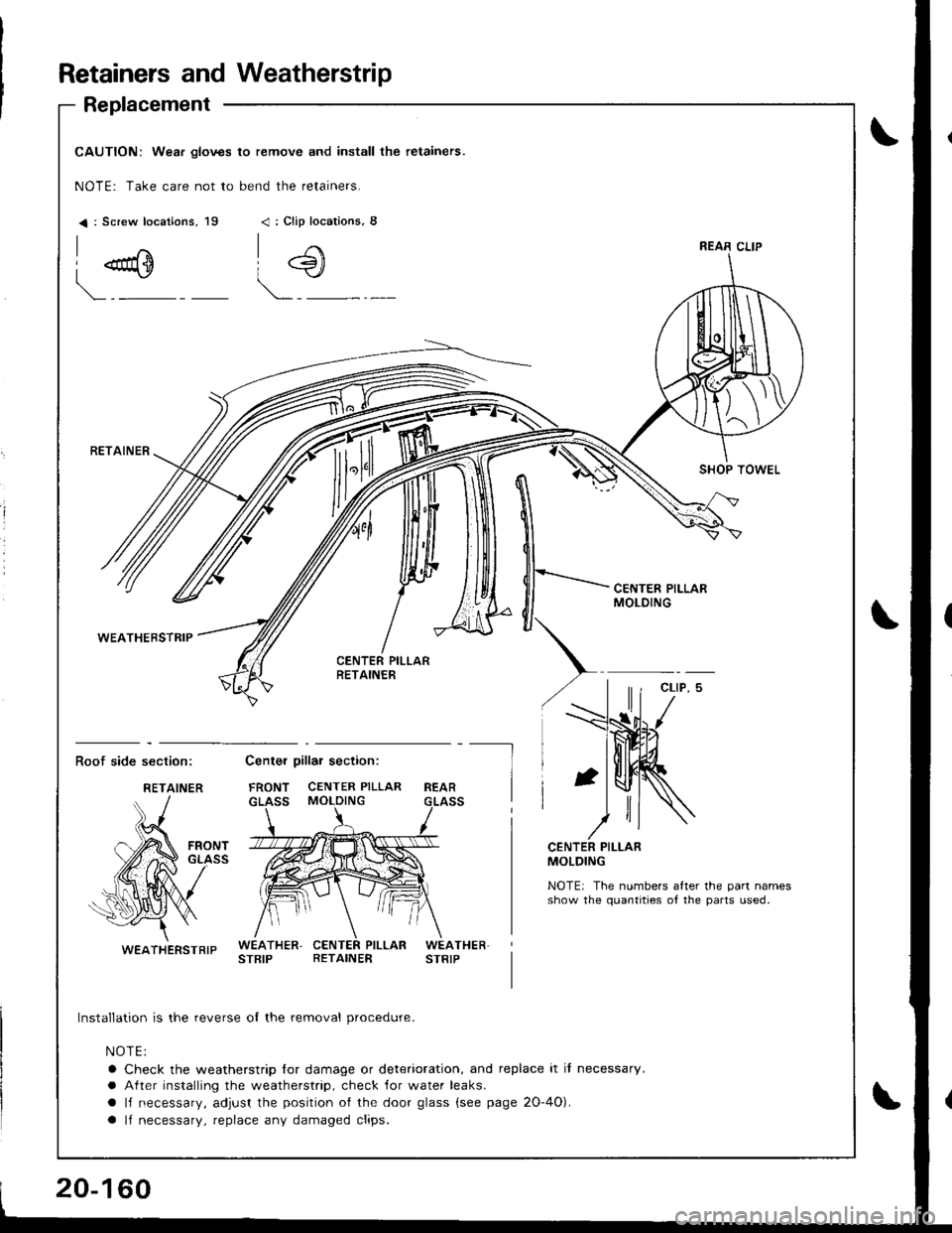
Retainers andWeatherstrip
Replacement
I
CAUTION: Wear glov3s to remove and install the retainers.
NOTE: Take care not to bend the retainers.
< : Screw locations, 19< : Clip locarions, 8
I "u+
\.-"
i4)
RETAINER
WEATHEBSTRIP
SHOP TOWEL
CEf{TER PILLARMOLDING
Roof side section:Center pillar section:
FRONT CENTER PILLAR
GLASS MOLDINGREAR
--l
I
FRONTGLASSCENTER PILLARMOLDING
NOTE: The numbers after the par1 namesshow the quantities ot the pans used.
WEATHER,STRIPPILLARWEATHER.STRIPRETAINER
Installation is the reverse of the removal procedure.
NOTE:
a Check the weatherstrip for damage or deterioration, and replace it it necessary.
a After installing the weatherstrip, check ,for water leaks.
a lJ necessary, adjust the position of the door glass (see page 2O-4O).
a ll necessary, replace any damaged clips.
REAR CLIP
RETAINER
WEATHERSTBIP
Page 976 of 1681
J
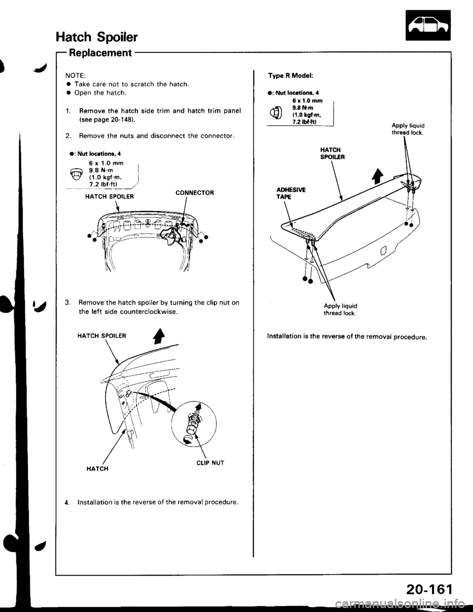
Hatch Spoiler
Replacement
NOTE:
a Take care not to scratch the hatch.
a Open the hatch.
1. Remove the hatch side trim and hatch trim panel
{see page 20-148}.
2. Remove the nuts and disconnect the connector.
a: Nut locltion3,4
Type R Model:
a: f{ut locltlona, 4
Apply liquidthread lock.
6 x 1.0 mm9.8Nm
{1.0 kgf m,7.2 tbt.ltl ./CONNECTOR
3. Remove the hatch spoiler by turning the clip nut on
the left side counterclockwise.Apply liquidthread lock.
Installation is the reverse of the removal procedure.HATCH SPOILER
HATCH
6x1.0mm9.8 N.m11.0 kgt.m,?.2 tbt.ftl
4. Installation is the reverse of the removal procedure.
20-161
Page 977 of 1681
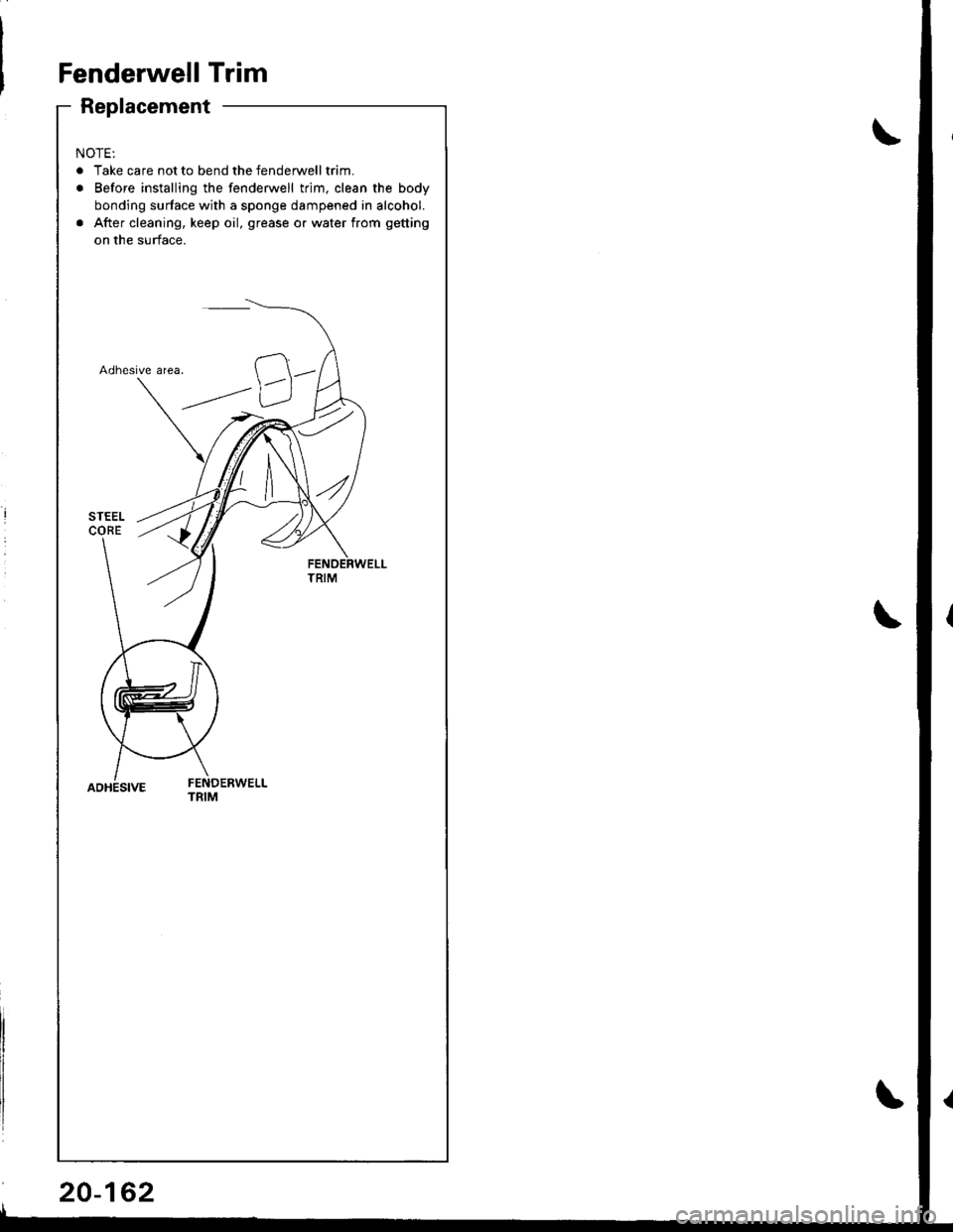
Fenderwell Trim
Replacement
NOTE:
. Take care not to bend the fenderwelltrim.
. Before installing the fenderwell trim, clean the body
bonding surface with a sponge dampened in alcohol.
. After cleaning, keep oil, grease o. water from getting
on the surface.
Adhesive area.
ADHESIVEFENDERWELLTRIM
20-162
Page 978 of 1681
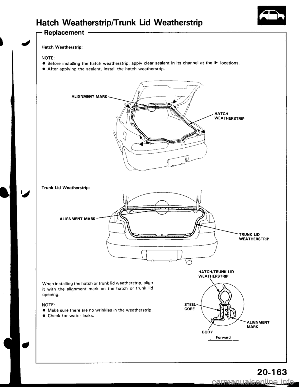
Hatch Weatherstrip/Trunk Lid Weatherstrip
Replacement
Hatch Weatherstrip:
NOTE:
a Before installing the hatch weatherstrip, apply clear sealant in its channel at the > locations.
a Alter applying the sealant, install the hatch weatherstrip.
ALIGNMENT MARK
HATCHWEATHERSTRIP
T.unk Lid Weatherstrip:
ALIGNMENT MARK
TRUNK LIDWEATIIERSTRIP
When installing the hatch or trunk lid weatherstrip, align
it with the alignment mark on the hatch or trunk lid
opening.
NOTE:
a Make sure there are no wrinkles in the weatherstrip.
a Check for water leaks.
ALIGNMENTMARK
BODY
Forward
20-163
Page 979 of 1681
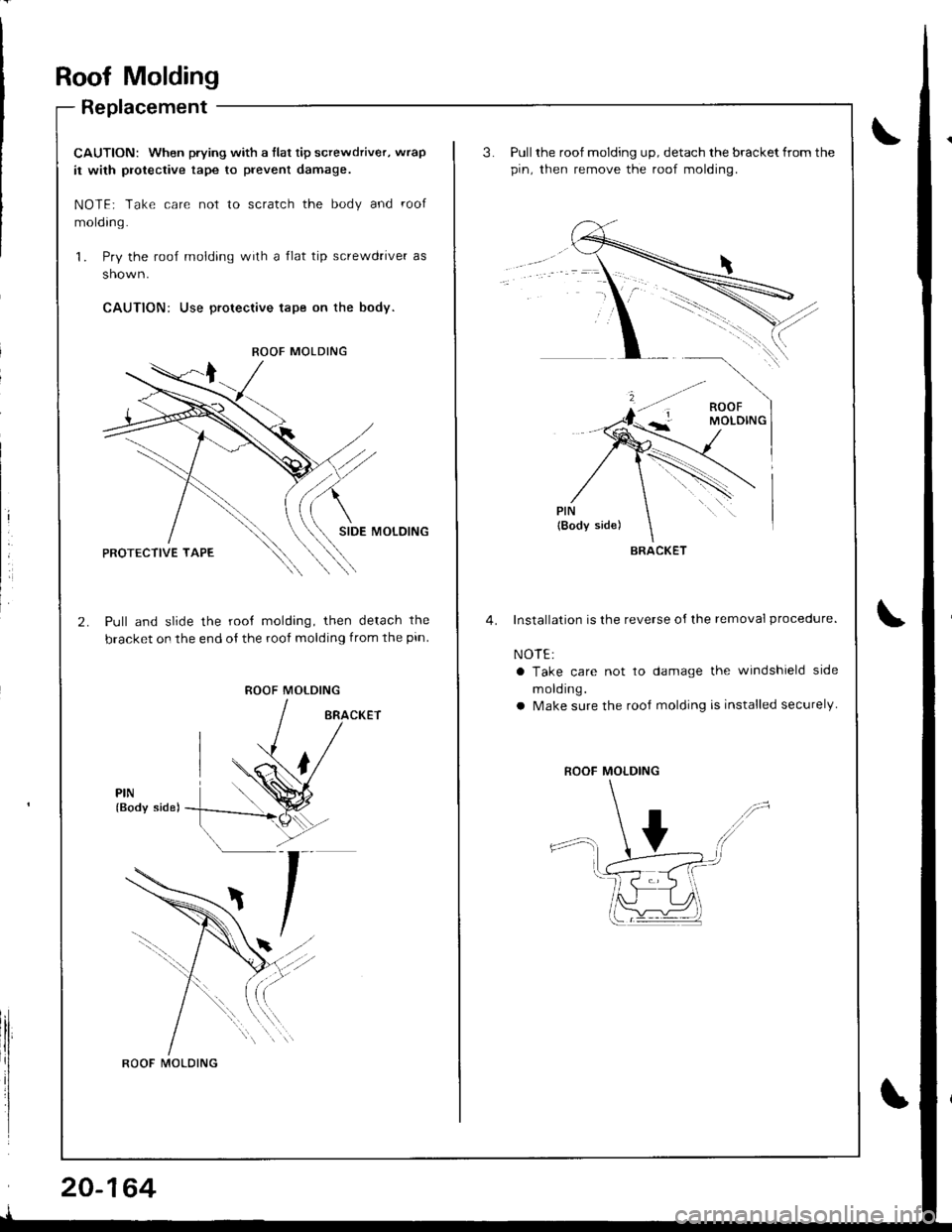
Roof Molding
Replacement
CAUTION: When prying with a flat tip screwdriver, wrap
it with protective tape to prevent damage.
NOTE; Take care not to scratch the body and roof
molding.
1. Pry the roof molding with a flat tip screwdrive. as
shown.
CAUTION: Use proteclive tape on the body.
SIDE MOLOING
Pull and slide the root molding, then detach the
bracket on the end of the roof molding from the pin
ROOF MOLDING
PIN(Body side)
ROOF MOLDING
ROOF MOLDING
20-164
Pull the roof molding up, detach the bracket from the
pin. then remove the roof molding.
Installation is the reverse oI lhe removal procedure.
NOTE:
a Take care not to damage the windshield side
m old ing.
a Make sure the rooJ molding is installed securely
BRACKET
ROOF MOLDING
Page 980 of 1681
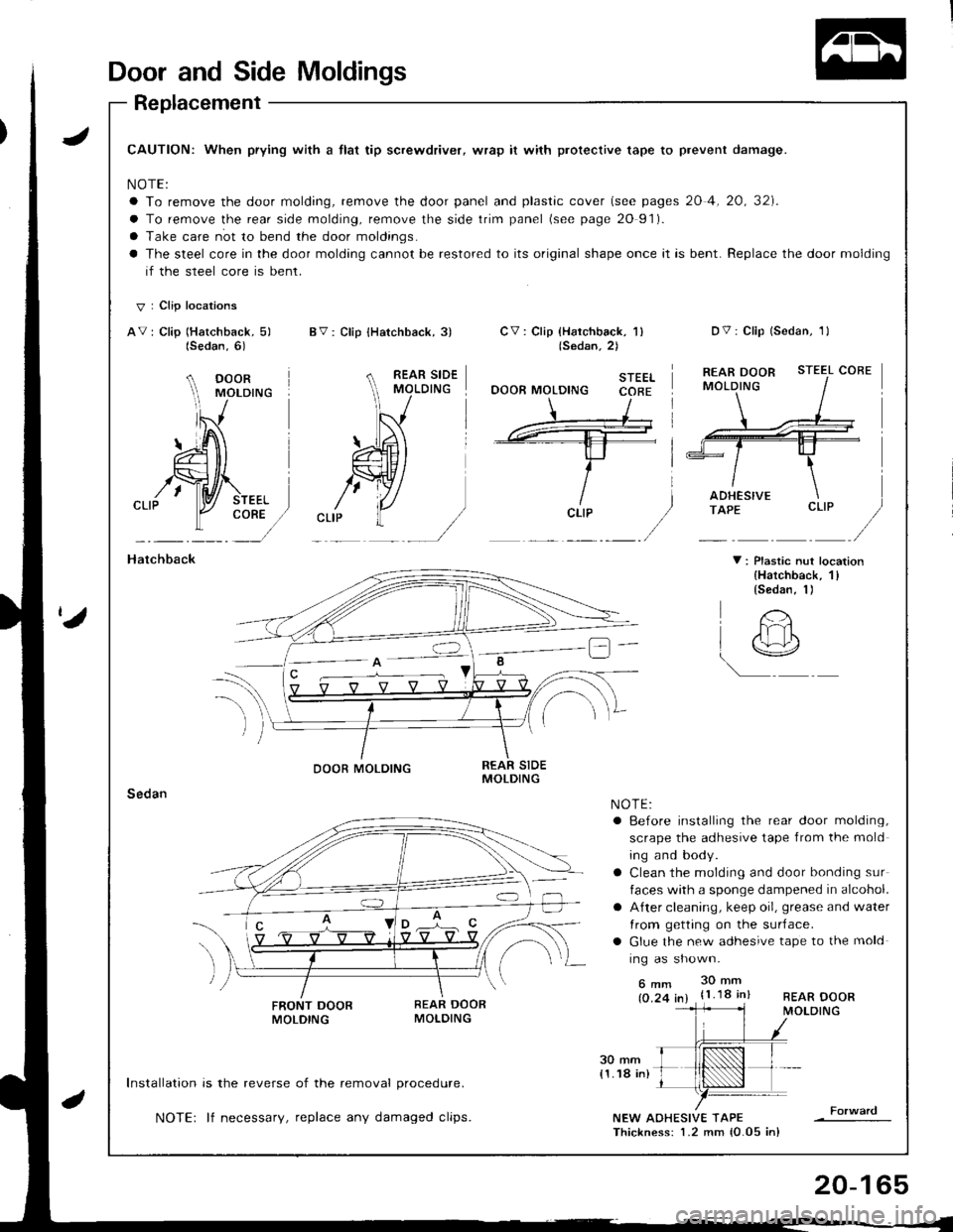
Door and Side Moldings
Replacement
JCAUTION: When prying with a tlat tip screwdriver, wrap it with protective tape to prevent damage.
NOTE:
a To remove the door molding, remove the door panel and plastic cover (see pages 20 4, 20, 32]'.
a To remove the rear side molding, remove the side trim panel (see page 20 91).
a Take care not to bend the door moldings.
a The steel core in the door molding cannot be restored to its original shape once it is bent. Replace the door molding
if the steel core is bent.
V I Clip locations
AV: Clip (Hatchback, 5) BV: Clip {Hatchback, 3)Dv: Clip lsedan, 1lCV : Clip {Harchback, 'l )(Sedan.2)
STEELOOOR MOLDING CORE
STEEL COBE
CORE
Hatchback
Sedan
V : Plastic nut location{Hatchback, 1llsedan, 1)
FRONT DOOBMOLDING
Installation is the reverse of the removal procedure.
NOTE: lf necessary, replace any damaged clips.NEW AOHESIVE TAPEThickness: 1.2 mm {0.05 in}
(Sedan,6)
A DOOR rvrororuc
lS
#'\---- -tl-t-f- i
ricLrP
/
REAR DOORMOLDING
O'
t
DOOR MOLDING
!@
NOTE:a Before installing the rear door molding,
scrape the adhesive tape from the mold
ing and body.
a Clean the molding and door bonding sur
faces with a sponge dampened in alcohol.
a A{ter cleaning, keep oil, grease and water
Irom getting on the surJace.
a Glue the new adhesive tape to the mold
ing as shown.
6mm 30mm
(0.24 in) {1.18 in}
20-165