HONDA INTEGRA 1998 4.G Workshop Manual
INTEGRA 1998 4.G
HONDA
HONDA
https://www.carmanualsonline.info/img/13/6069/w960_6069-0.png
HONDA INTEGRA 1998 4.G Workshop Manual
Trending: tow, roof rack, tire size, Stabilizer, Right wheel, fold seats, Power windows
Page 981 of 1681
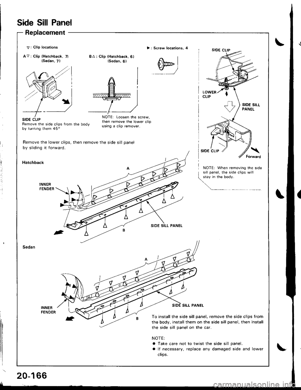
Side Sill Panel
Replacement
V : Clip locations
AV: Clip lHatchback, 7l
> : Screw locations, 4
(Sedan,
.t',/
BA: Clip (Hatchback, 6)lSedan,6)
@*,
stoE cLtPRemove the side clips from the bodyby turning them 45o
NOTE: Loosen the screw,then remove the lower clipusang a clip remover.
Remove the lower clips, then remove the side sill panel
by sliding it forward.
Hatchback
NOTE: When removrng the srde
qil:iJffi1""":
Sedan
INNERFENDER
SILI. PANEL
To install the side sill panel, remove the side clips from
the body, install them on the side sill panel, then install
the side sill panel on the car.
NOTE:
a Take care not to twist the side sill panel.
a lf necessary, replace any damaged side and lower
clips.
Page 982 of 1681
,'t
il
ii
II
APPLICATIONTAPEDOHC VTEC (GSR'
Special Edition {USA LS-S)EMBLEM
REAR TURNSIGNAL LIGHT
APPLICATIONTAPEOUTERTAILLIGHT
J
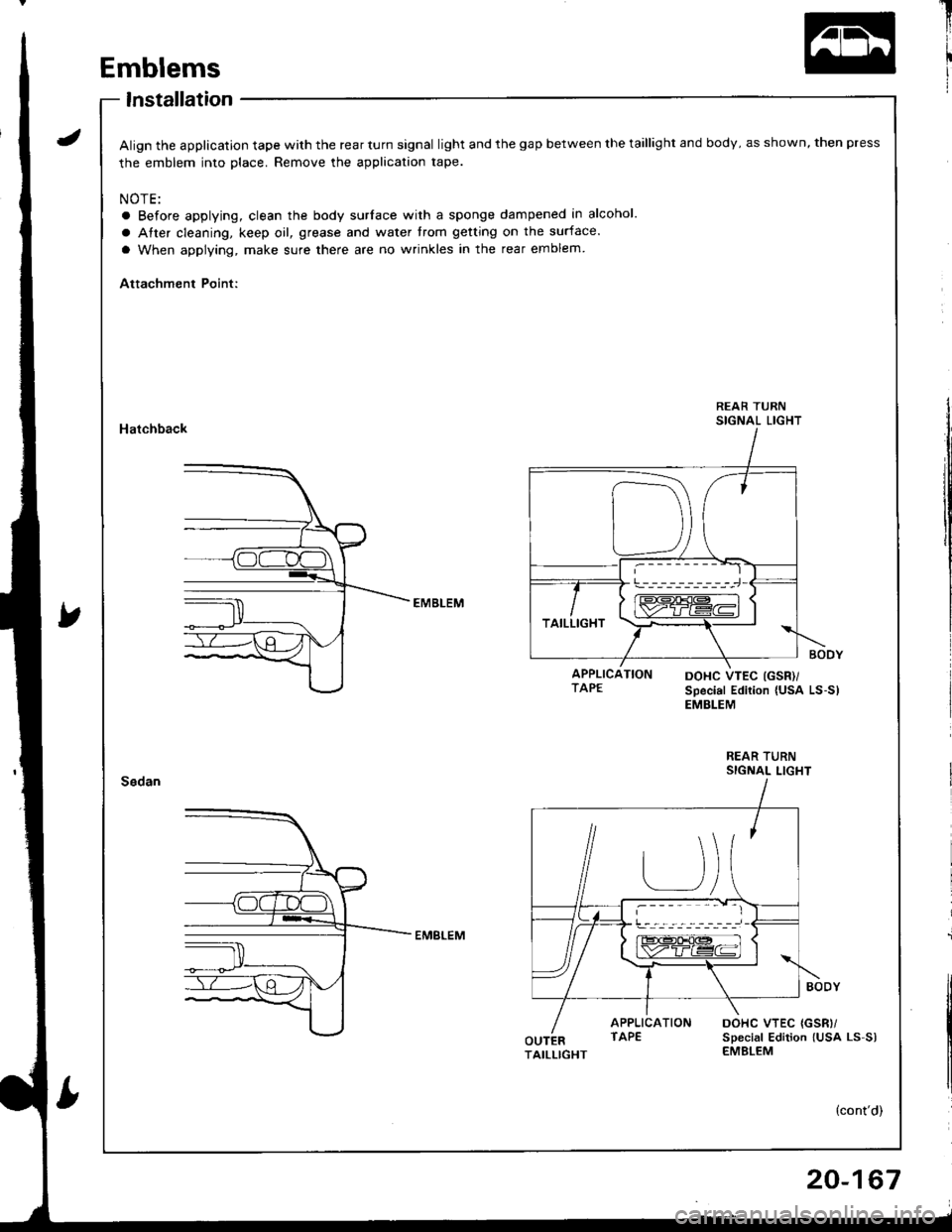
Emblems
lnstallation
Align the application tape with the rear turn signal light and the gap between the taillight and body, as shown, then press
the emblem into place. Remove the application tape.
NOTE:
a Before applying, clean the body surlace with a sponge dampened in alcohol.
a Atter cleaning, keep oil, grease and water trom getting on the surface.
a When applying, make sure there are no wrinkles in the rear emblem
Attachment Point:
Hatchback
REAR TURNSIGNAL LIGHT
DOHC VTEC {GSR)/sDecial Edition lUsa Ls-s)EMBLEM
20-167
Page 983 of 1681
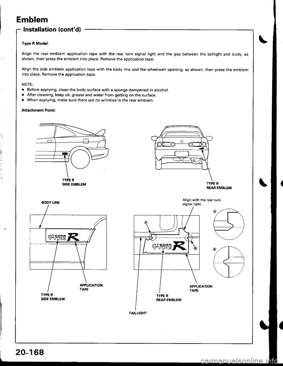
Emblem
Installation (cont'dl
Type R Mod€l:
Align the rear emblem application tape with the reaf turn signal light and the gap between the taillight and body, asshown, then press the emblem into place. Remove the application tape.
Align the side emblem application tape with the body line and the wheelwell opening, as shown, then press the embleminto place, Remove the application tape.
NOTE:
. Before applying. clean the body surface with a sponge dampened in alcohol.. After cleaning, keep oil, grease and water from getting on the surface.. When applying, make sure there are no wrinkles in the rear emblem.
Attachment Point:
i
l
TYPE RREAR EMBLEM
Align with the rear turnsagnal light.
TYPE RSIDE EMBLEM
TYPE R
BOOY UNE
20-168
TAILLIGHT
Page 984 of 1681
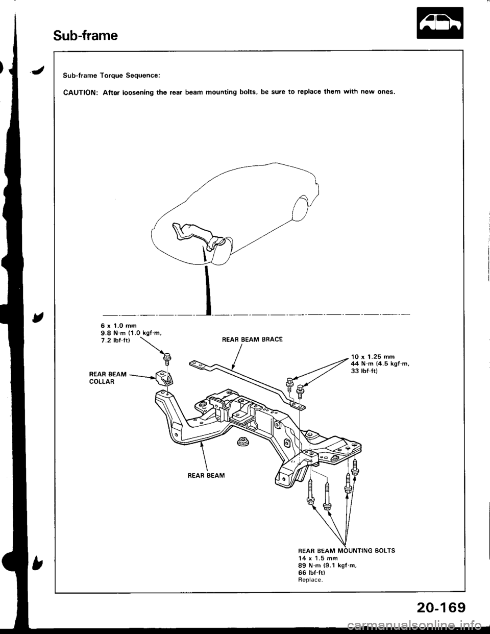
Sub-frame Torque Sequence:
CAUTION: Atter loosening the lea. beam mounting bolts. be sure to replace them with new ones.
6 x 1,0 mm9.8 N m (1.0 kgf m,7.2 rbf.ft)REAB BEAM BRACE
REAR BEAMCOLLAR
'10 x 1.25 mm44 N.m (4.5 kgl.m.33 tbf.ft)
REAR BEAM
REAR BEAM14 x 1.5 mm89 N m {9.1 kgf m.66 tbt.frlReplace.
Sub-frame
20-169
Page 985 of 1681
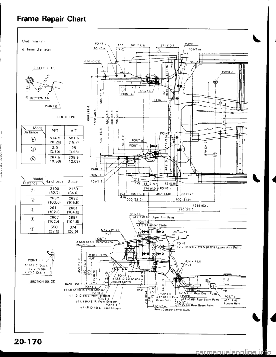
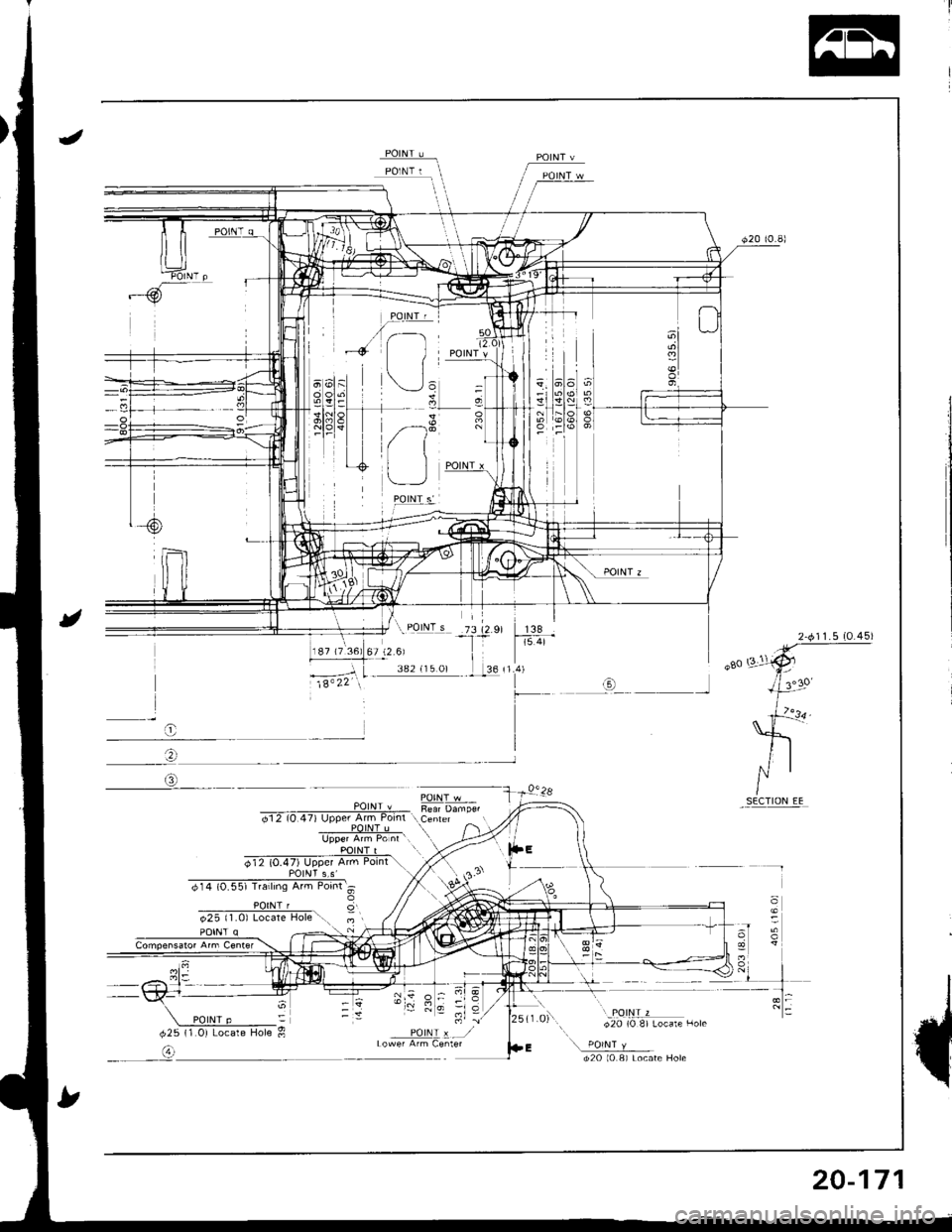
Frame Repair Chan
Unit: mm (in)
O: Inner diameter
2 elll119..19)
SECTION AA
cENTEF LINE 3
d13 5 {O 531
o16 t0 63)
102 302 1r r 9r
102
i, ?19:la 6l
35O (13.81
\friIPOlNrh.i / /a-rZr," tr, iii: 177(O69) l:205lO8l
SECTION BB, DD
d25 lr 0)
;
BASE LiNE
d11 5 (0.
@17 (O.661 Fea' Eeam Pornt
ModelDls6;G-\M/TA/T
UJ514.3\20.261501.5(19.7)
o(0.10)25(0.98)
@(1 0.53)305.5(12.03)
ModelDistt;d;--\HatchbackSedan
,i,2100\42.712150(84.6)
.,(1 03.6 )2682(105.6)
2611{102.8)2661(104.8)
o2607(1 02.6)2657{104.6)
.!-]558t22.Ol674126.51
20-170
o11 5 (0.45) L. Fronr StopperFront Oamper Lowef Sush
Page 986 of 1681
-tQ)
138i5.41
t
I
o
'rl n; ll s
POINI x --./
20-171
Page 987 of 1681
Page 988 of 1681
iii
i
I
J
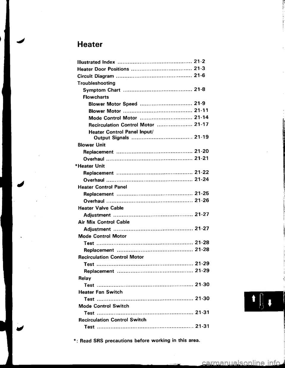
Heater
fffustrated Index ............. ......'..21-2
Heater Door Positions '....'........ 21-3
Circuit Diagram ....................... 21-6
Troubleshooting
Symptom Chart ............. '.....21-8
Flowcharts
Blower Motor Speed ...............'......'........ 21 -9
Blower Motor ............'......21-11
Mode Controf Motor ............ ............'... "' 21 -14
Recirculation Control Motor ......'...... "'.,.,. 21 -1 7
Heater Control Panel Input/
Output Signals ...'.......... 21-19
Blower Unit
Replacement ........ '....... ',..,.. 21-2O
Overhaul ",',..21-21
*Heater Unit
Repf acement .....'.....'........'.. 21'22
Overhaul .......21-24
Heater Control Panel
Repfacement ....... '..... '......... 21-25
Overhaul .......21-26
Heater Valve Cable
Adjustment '.. 21'27
Air Mix Control Cable
Adiustment ... 21-27
Mode Control Motor
Test .............. ..................... 21'24
Repfacement ....................... 21-24
Recirculation Control Motor
Test .............. ..................... 21-29
Repf acement .........'........ " ". 21-29
Relay
Test .............. ..................... 21-3O
Heater Fan Switch
Test .............. ....................' 21-30
Mode Control Switch
Test .............' "'..............'... 21-31
Recirculation Control Switch
Test .............. ..................... 21-31
*: Read SRS precautions before working in this area.
Page 989 of 1681
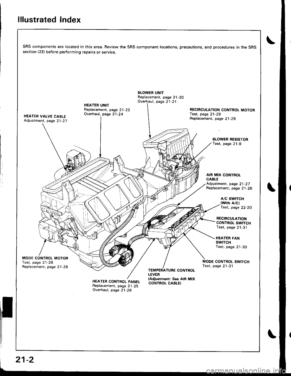
lllustrated Index
SRS components are located in this area. Review the SRS component locations. precautions, and procedures in the SRSsection (23) before performing repairs or service.
BLOWER UNITReplacement, page 21-2OOverhaul, page 21.21
HEATER VALVE CABLEAdiustment, page 21-27
HEATER UNITReplacement, page 21-22Overhaul, page 21-24RECIRCULATION CONTROL MOTORIest, page 21,29Seplacement, page 21-29
BLOWER RESISTORTest, page 21-9
AIR MIX CONTROLCABLEAdjustment, page 21-27Replacement, page 21-26
A/C SWTTCH{with A/clTest, page 22-20
RECIRCULATIONCONTROL SWITCHTest, page 21,31
HEATER FANswrTcHTest, page 21-30
MODE CONTROL MOTORTest, page 21-28Replacement, page 2 l -28CONTROL SWITCHTest, page 21-3'l
HEATER CONTROL PANELReplacement, page 21,25Overhaul, page 21-26
TEMPERATURE CONTROLLEVERlAdjustment: Soe AIR MIXCONTROL CABLEI
21-2
Page 990 of 1681
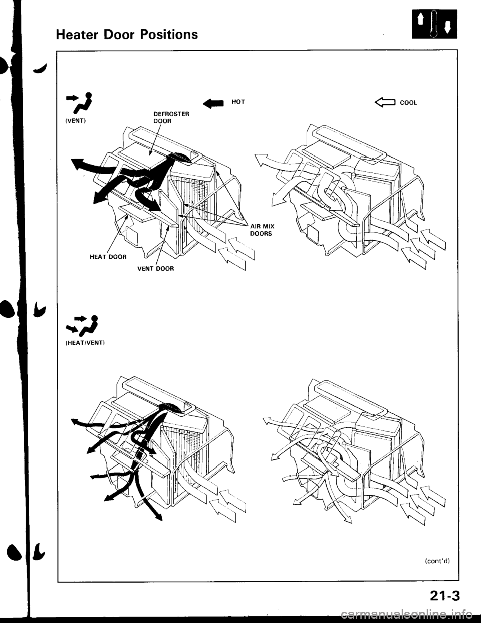
Heater Door Positions
II Horfr coor
r>O
t
IHEAT/VENTI
(cont'd)
VENT DOOR
21-3
Trending: recommended oil, clock, jump cable, Compressor, park assist, Friction damper, coolant reservoir
