vin INFINITI QX4 2001 Factory Service Manual
[x] Cancel search | Manufacturer: INFINITI, Model Year: 2001, Model line: QX4, Model: INFINITI QX4 2001Pages: 2395, PDF Size: 43.2 MB
Page 2184 of 2395

Special Service ToolsNBST0003The actual shapes of Kent-Moore tools may differ from those of special service tools illustrated here.
Tool number
(Kent-Moore No.)
Tool nameDescription
KV48100700
(J26364)
Torque adapter
NT169
Measuring pinion rotating torque
ST35300000
(Ð)
Drift
NT073
Installing power steering oil pump oil seal
a: 59 mm (2.32 in) dia.
b: 45 mm (1.77 in) dia.
ST27180001
(J25726-A)
Steering wheel puller
NT544
Removing steering wheel
ST29020001
(J24319-01)
Ball joint remover
NT694
Removing ball joint
a: 34 mm (1.34 in)
b: 6.5 mm (0.256 in)
c: 61.5 mm (2.421 in)
KV48103500
(J26357 and J26357-10)
Pressure gauge
NT547
Measuring oil pressure
KV48102500
(Ð)
Pressure gauge adapter
NT542
Measuring oil pressure
GI
MA
EM
LC
EC
FE
AT
TF
PD
AX
SU
BR
RS
BT
HA
SC
EL
IDX
PREPARATION
Special Service Tools
ST-3
Page 2185 of 2395

Tool number
(Kent-Moore No.)
Tool nameDescription
ST3127S000
(See J25765-A)
1 GG91030000
(J25765-A)
Torque wrench
2 HT62940000
(Ð)
Socket adapter
3 HT62900000
(Ð)
Socket adapter
NT541
Measuring turning torque
KV48104400
(Ð)
Rack seal ring reformer
NT550
Reforming teflon ring
a: 50 mm (1.97 in) dia.
b: 36 mm (1.42 in) dia.
c: 100 mm (3.94 in)
KV48103400
(Ð)
Torque adapter
NT236
Measuring steering transfer gear rotating
torque
KV48104200
(Ð)
Rear cover wrench
NT540
Removing and installing gear housing end
cover
a: 4 mm (0.16 in) dia.
b: 5 mm (0.20 in)
c: 3 mm (0.12 in) dia.
d: 5 mm (0.20 in)
(J43995)
Steering lock nut wrench
NT838
Adjusting steering pinion rotating torque
(J43996)
Steering rack adjustment
wrench
NT839
Adjusting steering pinion rotating torque
(J-44372)
Spring gauge
LST024
Measuring steering wheel turning force
PREPARATION
Special Service Tools (Cont'd)
ST-4
Page 2188 of 2395

SST489B
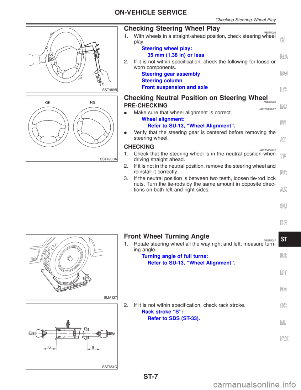
Checking Steering Wheel PlayNBST00051. With wheels in a straight-ahead position, check steering wheel
play.
Steering wheel play:
35 mm (1.38 in) or less
2. If it is not within specification, check the following for loose or
worn components.
Steering gear assembly
Steering column
Front suspension and axle
SST490BA
Checking Neutral Position on Steering WheelNBST0006PRE-CHECKINGNBST0006S01IMake sure that wheel alignment is correct.
Wheel alignment:
Refer to SU-13, ªWheel Alignmentº.
IVerify that the steering gear is centered before removing the
steering wheel.
CHECKINGNBST0006S021. Check that the steering wheel is in the neutral position when
driving straight ahead.
2. If it is not in the neutral position, remove the steering wheel and
reinstall it correctly.
3. If the neutral position is between two teeth, loosen tie-rod lock
nuts. Turn the tie-rods by the same amount in opposite direc-
tions on both left and right sides.
SMA127
Front Wheel Turning AngleNBST00071. Rotate steering wheel all the way right and left; measure turn-
ing angle.
Turning angle of full turns:
Refer to SU-13, ªWheel Alignmentº.
SST651C
2. If it is not within specification, check rack stroke.
Rack stroke ªSº:
Refer to SDS (ST-33).
GI
MA
EM
LC
EC
FE
AT
TF
PD
AX
SU
BR
RS
BT
HA
SC
EL
IDX
ON-VEHICLE SERVICE
Checking Steering Wheel Play
ST-7
Page 2189 of 2395

SST601C
Checking Gear Housing MovementNBST00081. Check the movement of steering gear housing during station-
ary steering on a dry paved surface.
IApply a force of 49 N (5 kg, 11 lb) to steering wheel to check
the gear housing movement.
Turn off ignition key while checking.
Movement of gear housing:
±2mm(±0.08 in) or less
2. If movement exceeds the limit, replace mount insulator after
confirming proper installation of gear housing clamps.
SST602C
Adjusting Rack RetainerNBST0009IPerform this driving test on a flat road.
a) Check whether vehicle moves in a straight line when steering
wheel is released.
b) Check whether steering wheel returns to neutral position when
steering wheel is released from a slightly turned (approx. 20É)
position.
IIf any abnormality is found, correct it by resetting adjusting
screw.
Checking and Adjusting Drive BeltsNBST0010Refer to MA-13, ªChecking Drive Beltsº.
SST280BA
Checking Fluid LevelNBST0011Check fluid level.
Use the correct range of the dipstick depending on the fluid tem-
perature. Use the ªHOTº range at 50 to 80ÉC (122 to 176ÉF), or the
ªCOLDº range at 0 to 30ÉC (32 to 86ÉF).
CAUTION:
IDo not overfill.
IRecommended fluid is Genuine Nissan PSF II or equiva-
lent. Refer to MA-11, ªFluids and Lubricantsº.
SST458C
Checking Fluid LeakageNBST0012Check the lines for improper attachment and for leaks, cracks,
damage, loose connections, chafing and deterioration.
1. Run engine between idle speed and 1,000 rpm.
Make sure temperature of fluid in oil tank rises to 60 to 80ÉC
(140 to 176ÉF).
2. Turn steering wheel right-to-left several times.
3. Hold steering wheel at each ªlockº position for five seconds
and carefully check for fluid leakage.
ON-VEHICLE SERVICE
Checking Gear Housing Movement
ST-8
Page 2191 of 2395

6. If rack sliding force is not within specification, overhaul steer-
ing gear assembly.
7. If rack sliding force is OK, inspect steering column. Refer to
ªInspectionº, ªSTEERING WHEEL AND STEERING
COLUMNº, ST-14.
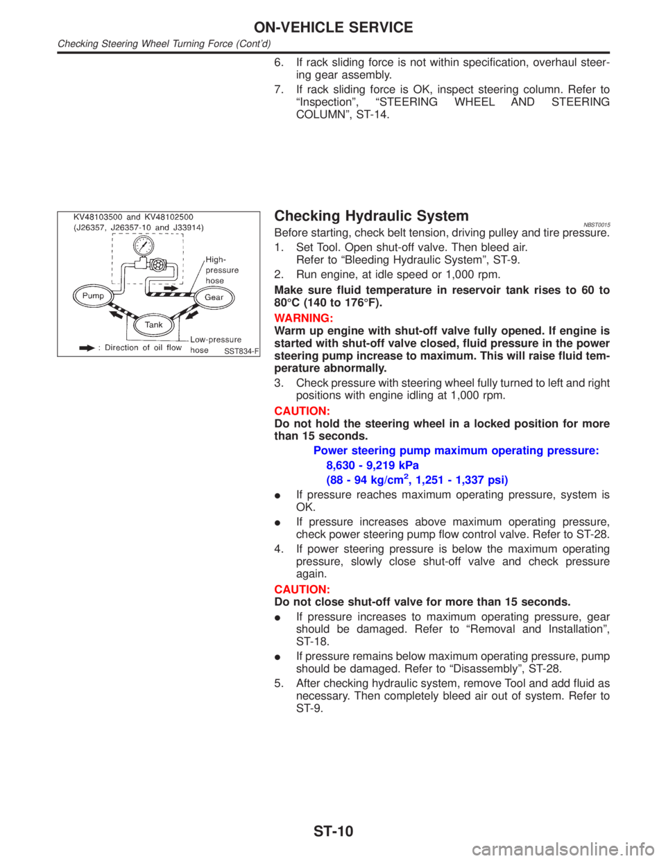
SST834-F
Checking Hydraulic SystemNBST0015Before starting, check belt tension, driving pulley and tire pressure.
1. Set Tool. Open shut-off valve. Then bleed air.
Refer to ªBleeding Hydraulic Systemº, ST-9.
2. Run engine, at idle speed or 1,000 rpm.
Make sure fluid temperature in reservoir tank rises to 60 to
80ÉC (140 to 176ÉF).
WARNING:
Warm up engine with shut-off valve fully opened. If engine is
started with shut-off valve closed, fluid pressure in the power
steering pump increase to maximum. This will raise fluid tem-
perature abnormally.
3. Check pressure with steering wheel fully turned to left and right
positions with engine idling at 1,000 rpm.
CAUTION:
Do not hold the steering wheel in a locked position for more
than 15 seconds.
Power steering pump maximum operating pressure:
8,630 - 9,219 kPa
(88 - 94 kg/cm
2, 1,251 - 1,337 psi)
IIf pressure reaches maximum operating pressure, system is
OK.
IIf pressure increases above maximum operating pressure,
check power steering pump flow control valve. Refer to ST-28.
4. If power steering pressure is below the maximum operating
pressure, slowly close shut-off valve and check pressure
again.
CAUTION:
Do not close shut-off valve for more than 15 seconds.
IIf pressure increases to maximum operating pressure, gear
should be damaged. Refer to ªRemoval and Installationº,
ST-18.
IIf pressure remains below maximum operating pressure, pump
should be damaged. Refer to ªDisassemblyº, ST-28.
5. After checking hydraulic system, remove Tool and add fluid as
necessary. Then completely bleed air out of system. Refer to
ST-9.
ON-VEHICLE SERVICE
Checking Steering Wheel Turning Force (Cont'd)
ST-10
Page 2192 of 2395

ComponentsNBST0016
SST843C
1. Air bag module
2. Steering wheel3. Spiral cable
4. Combination switch5. Steering column assembly
6. Column cover
CAUTION:
IThe rotation of the spiral cable (SRS ªAIR BAGº compo-
nent part) is limited. If the steering gear must be removed,
set the front wheels in the straight-ahead direction. Do not
rotate the steering column while the steering gear is
removed.
IRemove the steering wheel before removing the steering
lower joint to avoid damaging the SRS spiral cable.
SBF812E
Removal and InstallationNBST0017STEERING WHEELNBST0017S011. Remove air bag module and spiral cable. Refer to RS-17,
ªRemoval Ð Air Bag Module and Spiral Cableº.
GI
MA
EM
LC
EC
FE
AT
TF
PD
AX
SU
BR
RS
BT
HA
SC
EL
IDX
STEERING WHEEL AND STEERING COLUMN
Components
ST-11
Page 2199 of 2395

Removal and InstallationNBST0027
SST614C
1. Gear and linkage assembly
2. Rack mounting insulator3. Gear housing mounting bracket 4. Cotter pin
SFA756B
CAUTION:
IThe rotation of the spiral cable (SRS ªAIR BAGº compo-
nent part) is limited. If the steering gear must be removed,
set the front wheels in the straight-ahead direction. Do not
rotate the steering column while the steering gear is
removed.
IRemove the steering wheel before removing the steering
lower joint to avoid damaging the SRS spiral cable.
IDetach tie-rod outer sockets from knuckle arms with Tool.
SST615C
IInstall pipe connector.
IObserve specified tightening torque when tightening high-pres-
sure and low-pressure pipe connectors. Excessive tightening
will damage threads of connector or O-ring.
Connector tightening torque:
Low-pressure side ª1º
30 - 35 N´m (3.1 - 3.6 kg-m, 22 - 26 ft-lb)
High-pressure side ª2º
30 - 35 N´m (3.1 - 3.6 kg-m, 22 - 26 ft-lb)
IThe O-ring in low-pressure pipe connector is larger than that
POWER STEERING GEAR AND LINKAGE
Removal and Installation
ST-18
Page 2200 of 2395

in high-pressure connector. Take care to install the proper
O-ring.
SST616C
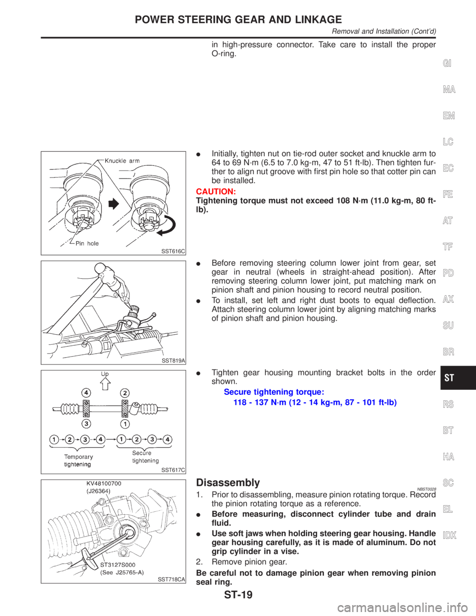
IInitially, tighten nut on tie-rod outer socket and knuckle arm to
64 to 69 N´m (6.5 to 7.0 kg-m, 47 to 51 ft-lb). Then tighten fur-
ther to align nut groove with first pin hole so that cotter pin can
be installed.
CAUTION:
Tightening torque must not exceed 108 N´m (11.0 kg-m, 80 ft-
lb).
SST819A
IBefore removing steering column lower joint from gear, set
gear in neutral (wheels in straight-ahead position). After
removing steering column lower joint, put matching mark on
pinion shaft and pinion housing to record neutral position.
ITo install, set left and right dust boots to equal deflection.
Attach steering column lower joint by aligning matching marks
of pinion shaft and pinion housing.
SST617C
ITighten gear housing mounting bracket bolts in the order
shown.
Secure tightening torque:
118 - 137 N´m (12 - 14 kg-m, 87 - 101 ft-lb)
SST718CA
DisassemblyNBST00281. Prior to disassembling, measure pinion rotating torque. Record
the pinion rotating torque as a reference.
IBefore measuring, disconnect cylinder tube and drain
fluid.
IUse soft jaws when holding steering gear housing. Handle
gear housing carefully, as it is made of aluminum. Do not
grip cylinder in a vise.
2. Remove pinion gear.
Be careful not to damage pinion gear when removing pinion
seal ring.
GI
MA
EM
LC
EC
FE
AT
TF
PD
AX
SU
BR
RS
BT
HA
SC
EL
IDX
POWER STEERING GEAR AND LINKAGE
Removal and Installation (Cont'd)
ST-19
Page 2209 of 2395

DisassemblyNBST0034CAUTION:
IParts which can be disassembled are strictly limited.
Never disassemble parts other than those specified.
IDisassemble in as clean a place as possible.
IClean your hands before disassembly.
IDo not use rags; use nylon cloths or paper towels.
IFollow the procedures and cautions in the Service
Manual.
IWhen disassembling and reassembling, do not let foreign
matter enter or contact the parts.
1. Fix power steering pump to vise.
CAUTION:
When fixing the pump to vise, use an aluminum plate or such
to avoid damaging the fitting plane of the steering pump.
2. Remove the front bracket mounting bolt, and remove the front
bracket from the casing.
3. Remove the rear cover mounting bolt, and remove the rear
cover from the casing.
4. Remove the O-ring from the casing.
SST926C
5. Remove side plate (rear side) from cam ring, then remove side
plate inner/outer seals from side plate (rear side).
6. Remove rotor snap ring using snap ring pliers, and remove
pulley from casing.
CAUTION:
Do not damage pulley shaft when removing rotor snap ring.
SST928C
7. Remove the followings from casing.
ICam ring
IRotor
IVane
ISide plate (front side)
IFlow control A valve
IFlow control valve spring
IFlow control B valve assembly
CAUTION:
Be careful not to drop flow control valve.
8. Remove inlet connector mounting bolt, and remove inlet con-
nector from casing.
9. Remove inlet connector seal from inlet connector.
10. Remove drive shaft seal from casing with a screwdriver.
CAUTION:
Do not damage casing surface with the screwdriver.
POWER STEERING OIL PUMP
Disassembly
ST-28
Page 2210 of 2395

InspectionNBST0035IIf pulley is cracked or deformed, replace it.
IIf an oil leak is found around pulley shaft oil seal, replace the
seal.
ICheck the casing and the inside of the rear body for damage.
If damages are found in the rear body, replace the entire rear
body. If the casing is damaged, replace the entire power steer-
ing pump as an assembly.
ICheck the cam ring for damage. If damage is found, replace
the cam ring, rotor and vane as a set.
ICheck the side plates (front and rear) for damage. If damage
is found, replace the side plates as a set (front and rear).
SST934C
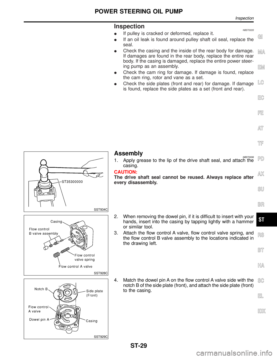
AssemblyNBST00361. Apply grease to the lip of the drive shaft seal, and attach the
casing.
CAUTION:
The drive shaft seal cannot be reused. Always replace after
every disassembly.
SST928C
2. When removing the dowel pin, if it is difficult to insert with your
hands, insert into the casing by tapping lightly with a hammer
or similar tool.
3. Attach the flow control A valve, flow control valve spring, and
the flow control B valve assembly to the locations indicated in
the drawing left.
SST929C
4. Match the dowel pin A on the flow control A valve side with the
notch B of the side plate (front), and attach the side plate (front)
to the casing.
GI
MA
EM
LC
EC
FE
AT
TF
PD
AX
SU
BR
RS
BT
HA
SC
EL
IDX
POWER STEERING OIL PUMP
Inspection
ST-29