vin INFINITI QX4 2001 Factory Service Manual
[x] Cancel search | Manufacturer: INFINITI, Model Year: 2001, Model line: QX4, Model: INFINITI QX4 2001Pages: 2395, PDF Size: 43.2 MB
Page 2217 of 2395
SBR686C
Precautions
PRECAUTIONSNBSU0001IWhen installing rubber parts, final tightening must be car-
ried out under unladen condition* with tires on ground.
*Fuel, radiator coolant and engine oil full. Spare tire, jack,
hand tools and mats in designated positions.
IUse flare nut wrench when removing and installing brake
tubes.
IAfter installing removed suspension parts, check wheel
alignment and adjust if necessary.
IAlways torque brake lines when installing.
Preparation
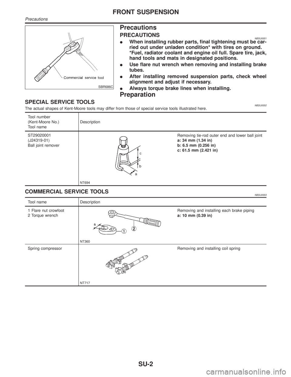
SPECIAL SERVICE TOOLSNBSU0002The actual shapes of Kent-Moore tools may differ from those of special service tools illustrated here.
Tool number
(Kent-Moore No.)
Tool nameDescription
ST29020001
(J24319-01)
Ball joint remover
NT694
Removing tie-rod outer end and lower ball joint
a: 34 mm (1.34 in)
b: 6.5 mm (0.256 in)
c: 61.5 mm (2.421 in)
COMMERCIAL SERVICE TOOLSNBSU0003
Tool name Description
1 Flare nut crowfoot
2 Torque wrench
NT360
Removing and installing each brake piping
a: 10 mm (0.39 in)
Spring compressor
NT717
Removing and installing coil spring
FRONT SUSPENSION
Precautions
SU-2
Page 2225 of 2395
SFA725B
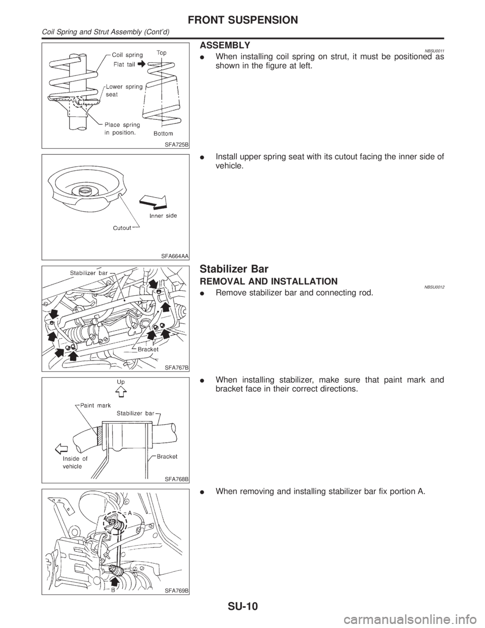
ASSEMBLYNBSU0011IWhen installing coil spring on strut, it must be positioned as
shown in the figure at left.
SFA664AA
IInstall upper spring seat with its cutout facing the inner side of
vehicle.
SFA767B
Stabilizer Bar
REMOVAL AND INSTALLATIONNBSU0012IRemove stabilizer bar and connecting rod.
SFA768B
IWhen installing stabilizer, make sure that paint mark and
bracket face in their correct directions.
SFA769B
IWhen removing and installing stabilizer bar fix portion A.
FRONT SUSPENSION
Coil Spring and Strut Assembly (Cont'd)
SU-10
Page 2230 of 2395

SBR686C
Precautions
PRECAUTIONSNBSU0021IWhen installing rubber parts, final tightening must be car-
ried out under unladen condition* with tires on ground.
*Fuel, radiator coolant and engine oil full. Spare tire, jack,
hand tools and mats in designated positions.
IUse flare nut wrench when removing and installing brake
tubes.
IAfter installing removed suspension parts, check wheel
alignment and adjust if necessary.
IAlways torque brake lines when installing.
Preparation
COMMERCIAL SERVICE TOOLSNBSU0023
Tool name Description
1 Flare nut crowfoot
2 Torque wrench
NT360
Removing and installing each brake piping
a: 10 mm (0.39 in)
Noise, Vibration and Harshness (NVH)
Troubleshooting
NBSU0036Refer to ªNoise, Vibration and Harshness (NVH) Troubleshootingº,
ªFRONT SUSPENSIONº, SU-3.
GI
MA
EM
LC
EC
FE
AT
TF
PD
AX
BR
ST
RS
BT
HA
SC
EL
IDX
REAR SUSPENSION
Precautions
SU-15
Page 2232 of 2395

SBR686C
Removal and InstallationNBSU00261. Support axle and suspension components with a suitable jack
and block.
2. Disconnect brake hydraulic line and parking brake cables at
back plates.
CAUTION:
IUse flare nut wrench when removing and installing brake
tubes.
IBefore removing the rear suspension assembly, discon-
nect the ABS wheel sensor from the assembly. Then move
it away from the rear suspension assembly. Failure to do
so may result in damage to the sensor wires and the sen-
sor becoming inoperative.
3. Remove stabilizer bar from body.
4. Remove upper links and lower links from body.
5. Remove panhard rod from body.
6. Disconnect rear end of propeller shaft. Refer to PD-6,
ªRemoval and Installationº.
7. Remove upper end nuts of shock absorber.
SRA935
Final tightening for rubber parts requires to be carried out
under unladen condition with tires on ground.
GI
MA
EM
LC
EC
FE
AT
TF
PD
AX
BR
ST
RS
BT
HA
SC
EL
IDX
REAR SUSPENSION
Removal and Installation
SU-17
Page 2235 of 2395
INSTALLATIONNBSU0032When installing each link, pay attention to direction of nuts
and bolts.
When installing each rubber part, final tightening must be car-
ried out under unladen condition with tires on ground.
SRA766A
Stabilizer Bar
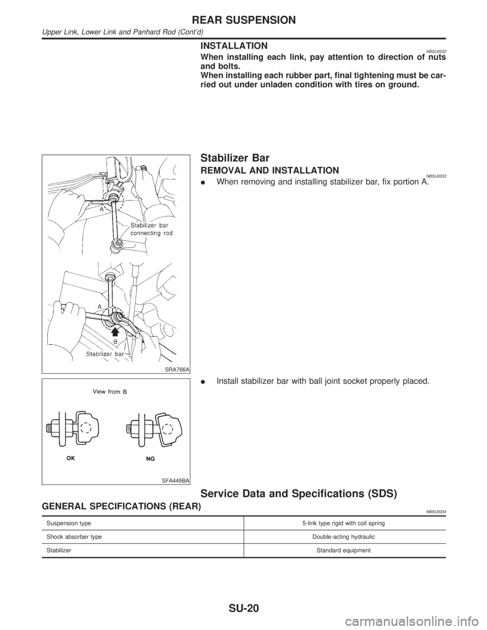
REMOVAL AND INSTALLATIONNBSU0033IWhen removing and installing stabilizer bar, fix portion A.
SFA449BA
IInstall stabilizer bar with ball joint socket properly placed.
Service Data and Specifications (SDS)
GENERAL SPECIFICATIONS (REAR)NBSU0034
Suspension type5-link type rigid with coil spring
Shock absorber typeDouble-acting hydraulic
StabilizerStandard equipment
REAR SUSPENSION
Upper Link, Lower Link and Panhard Rod (Cont'd)
SU-20
Page 2240 of 2395
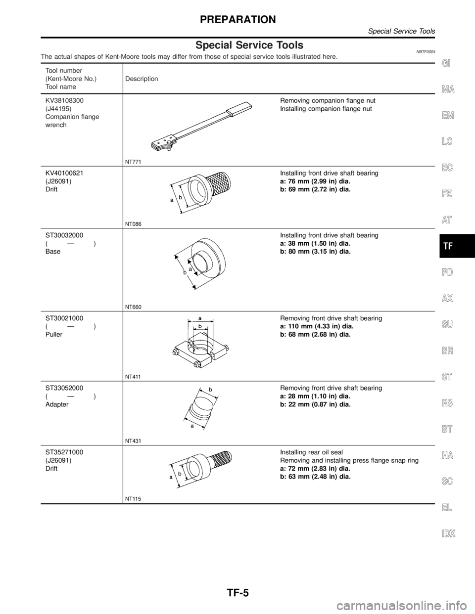
Special Service ToolsNBTF0004The actual shapes of Kent-Moore tools may differ from those of special service tools illustrated here.
Tool number
(Kent-Moore No.)
Tool nameDescription
KV38108300
(J44195)
Companion flange
wrench
NT771
Removing companion flange nut
Installing companion flange nut
KV40100621
(J26091)
Drift
NT086
Installing front drive shaft bearing
a: 76 mm (2.99 in) dia.
b: 69 mm (2.72 in) dia.
ST30032000
(Ð)
Base
NT660
Installing front drive shaft bearing
a: 38 mm (1.50 in) dia.
b: 80 mm (3.15 in) dia.
ST30021000
(Ð)
Puller
NT411
Removing front drive shaft bearing
a: 110 mm (4.33 in) dia.
b: 68 mm (2.68 in) dia.
ST33052000
(Ð)
Adapter
NT431
Removing front drive shaft bearing
a: 28 mm (1.10 in) dia.
b: 22 mm (0.87 in) dia.
ST35271000
(J26091)
Drift
NT115
Installing rear oil seal
Removing and installing press flange snap ring
a: 72 mm (2.83 in) dia.
b: 63 mm (2.48 in) dia.
GI
MA
EM
LC
EC
FE
AT
PD
AX
SU
BR
ST
RS
BT
HA
SC
EL
IDX
PREPARATION
Special Service Tools
TF-5
Page 2241 of 2395
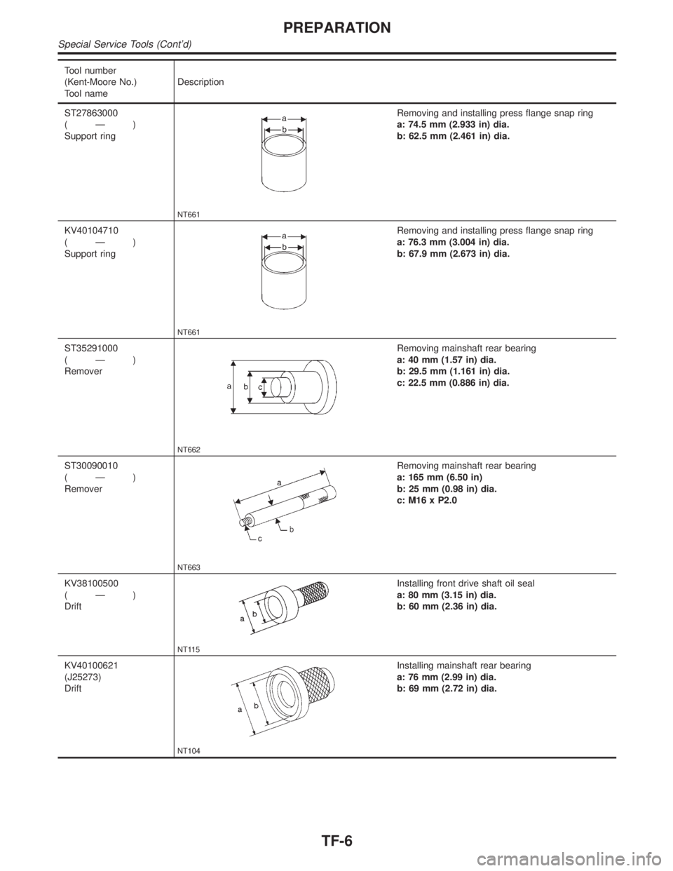
Tool number
(Kent-Moore No.)
Tool nameDescription
ST27863000
(Ð)
Support ring
NT661
Removing and installing press flange snap ring
a: 74.5 mm (2.933 in) dia.
b: 62.5 mm (2.461 in) dia.
KV40104710
(Ð)
Support ring
NT661
Removing and installing press flange snap ring
a: 76.3 mm (3.004 in) dia.
b: 67.9 mm (2.673 in) dia.
ST35291000
(Ð)
Remover
NT662
Removing mainshaft rear bearing
a: 40 mm (1.57 in) dia.
b: 29.5 mm (1.161 in) dia.
c: 22.5 mm (0.886 in) dia.
ST30090010
(Ð)
Remover
NT663
Removing mainshaft rear bearing
a: 165 mm (6.50 in)
b: 25 mm (0.98 in) dia.
c: M16 x P2.0
KV38100500
(Ð)
Drift
NT115
Installing front drive shaft oil seal
a: 80 mm (3.15 in) dia.
b: 60 mm (2.36 in) dia.
KV40100621
(J25273)
Drift
NT104
Installing mainshaft rear bearing
a: 76 mm (2.99 in) dia.
b: 69 mm (2.72 in) dia.
PREPARATION
Special Service Tools (Cont'd)
TF-6
Page 2242 of 2395

Tool number
(Kent-Moore No.)
Tool nameDescription
KV32101100
(Ð)
Pin punch
NT410
Removing and installing L-H fork, 2-4 fork
a: 6 mm (0.24 in) dia.
ST3306S001
(J22888-D)
Differential side bearing
puller set
1: ST33051001
(Ð)
Puller
2: ST33061000
(J8107-2)
Adapter
NT072
Installing mainshaft rear bearing
Removing sun gear assembly
a: 28.5 mm (1.122 in) dia.
b: 38 mm (1.50 in) dia.
ST30911000
(Ð)
Puller
NT664
Installing mainshaft and planetary carrier assembly
a: 98 mm (3.86 in) dia.
b: 40.5 mm (1.594 in) dia.
KV381054S0
(Ð)
Outer race puller
NT665
Removing rear oil seal
KV40105230
(Ð)
Adapter
NT666
Installing planetary carrier assembly
a: 92 mm (3.62 in) dia.
b: 86 mm (3.39 in) dia.
c: 12 mm (0.47 in)
KV40105310
(Ð)
Support ring
NT661
Installing planetary carrier assembly
a: 89.1 mm (3.508 in) dia.
b: 80.7 mm (3.177 in) dia.
GI
MA
EM
LC
EC
FE
AT
PD
AX
SU
BR
ST
RS
BT
HA
SC
EL
IDX
PREPARATION
Special Service Tools (Cont'd)
TF-7
Page 2243 of 2395

Tool number
(Kent-Moore No.)
Tool nameDescription
KV40105500
(Ð)
Support
NT667
Installing planetary carrier assembly
a: 69 mm (2.72 in) dia.
b: 52 mm (2.05 in) dia.
c: 120 mm (4.72 in) dia.
KV38100200
(Ð)
Drift
NT673
Installing transfer cover oil seal
a: 65 mm (2.56 in) dia.
b: 49 mm (1.93 in) dia.
KV31103300
(Ð)
Drift
NT668
Removing and installing press flange snap ring
a: 76.3 mm (3.004 in) dia.
b: 130 mm (5.12 in)
KV31103400
(Ð)
Clutch piston attachment
1 Shaft-drift
2 Guide-cylinder
NT669
Installing clutch piston
a: 88.5 mm (3.484 in) dia.
b: 158 mm (6.22 in) dia.
ST33290001
(J25810-A)
Puller
NT414
Removing center case oil seal
Removing rear oil seal
a: 250 mm (9.84 in)
b: 160 mm (6.30 in)
ST33051001
(J22888)
Puller
NT824
Removing companion flange
a: 135 mm (5.31 in)
b: 100 mm (3.94 in)
c: 170 mm (6.69 in)
PREPARATION
Special Service Tools (Cont'd)
TF-8
Page 2244 of 2395

Tool number
(Kent-Moore No.)
Tool nameDescription
(J35864)
Drift
NT671
Installing oil seal
Commercial Service ToolsNBTF0005
Tool name Description
Puller
NT077
Removing companion flange, clutch gear and
mainshaft gear bearing
GI
MA
EM
LC
EC
FE
AT
PD
AX
SU
BR
ST
RS
BT
HA
SC
EL
IDX
PREPARATION
Special Service Tools (Cont'd)
TF-9