vin INFINITI QX4 2001 Factory Service Manual
[x] Cancel search | Manufacturer: INFINITI, Model Year: 2001, Model line: QX4, Model: INFINITI QX4 2001Pages: 2395, PDF Size: 43.2 MB
Page 1784 of 2395

Diagnostic
test modeFunction ENGINEALL-
MODE
4WDA/T ABSAIR
BAGIVCS*1IVIS
(NATS)*2SMART
EN-
TRANCE
Registered
dataDisplay the VIN, etc. data
registered in the IVCS
unit.ÐÐÐÐÐ x ÐÐ
Configura-
tionIThe IVCS system can
be set up in the dem-
onstration mode to
confirm system opera-
tion.
IVarious data related to
both the Communica-
tor Response Center
contract and cellular
provider can be
written/rewritten in this
mode.ÐÐÐÐÐ x ÐÐ
REMO
CONT ID
SET UPA maximum of four IDs
(identifications) can be
registered in the memory
using the remote control-
ler. These IDs can be
also be confirmed and
erased as required.ÐÐÐÐÐÐÐ x
x: Applicable
*1: INFINITI Communicator (IVCS)
*2: IVIS (NATS) [INFINITI Vehicle Immobilizer System (Nissan Anti-Theft System)]
Nickel Metal Hydride Battery ReplacementNBGI0006S06CONSULT-II contains a nickel metal hydride battery. When replacing the battery obey the following:
WARNING:
Replace the nickel metal hydride battery with Genuine CONSULT-II battery only. Use of another bat-
tery may present a risk of fire or explosion. The battery may present a fire or chemical burn hazard if
mistreated. Do not recharge, disassemble of dispose of in fire.
Keep the battery out of reach of children and discard used battery conforming to the local regulations.
Checking EquipmentNBGI0006S07When ordering the below equipment, contact your NISSAN/INFINITI distributor.
Tool name Description
NISSAN CONSULT-II
q
1CONSULT-II unit (Tester internal soft:
Resident version 3.2.0) and accessories
q
2Program card AED99C (Version 3.0)
and UEN99A (For IVIS and IVCS)
To confirm the best combination of these
softwares, refer to CONSULT-II Operation
Manual.
SGI100A
NOTE:
IThe CONSULT-II must be used in conjunction with a program card.
CONSULT-II does not require loading (Initialization) procedure.
IBe sure the CONSULT-II is turned off before installing or removing a program card.
MA
EM
LC
EC
FE
AT
TF
PD
AX
SU
BR
ST
RS
BT
HA
SC
EL
IDX
CONSULT-II CHECKING SYSTEM
Function and System Application (Cont'd)
GI-39
Page 1792 of 2395
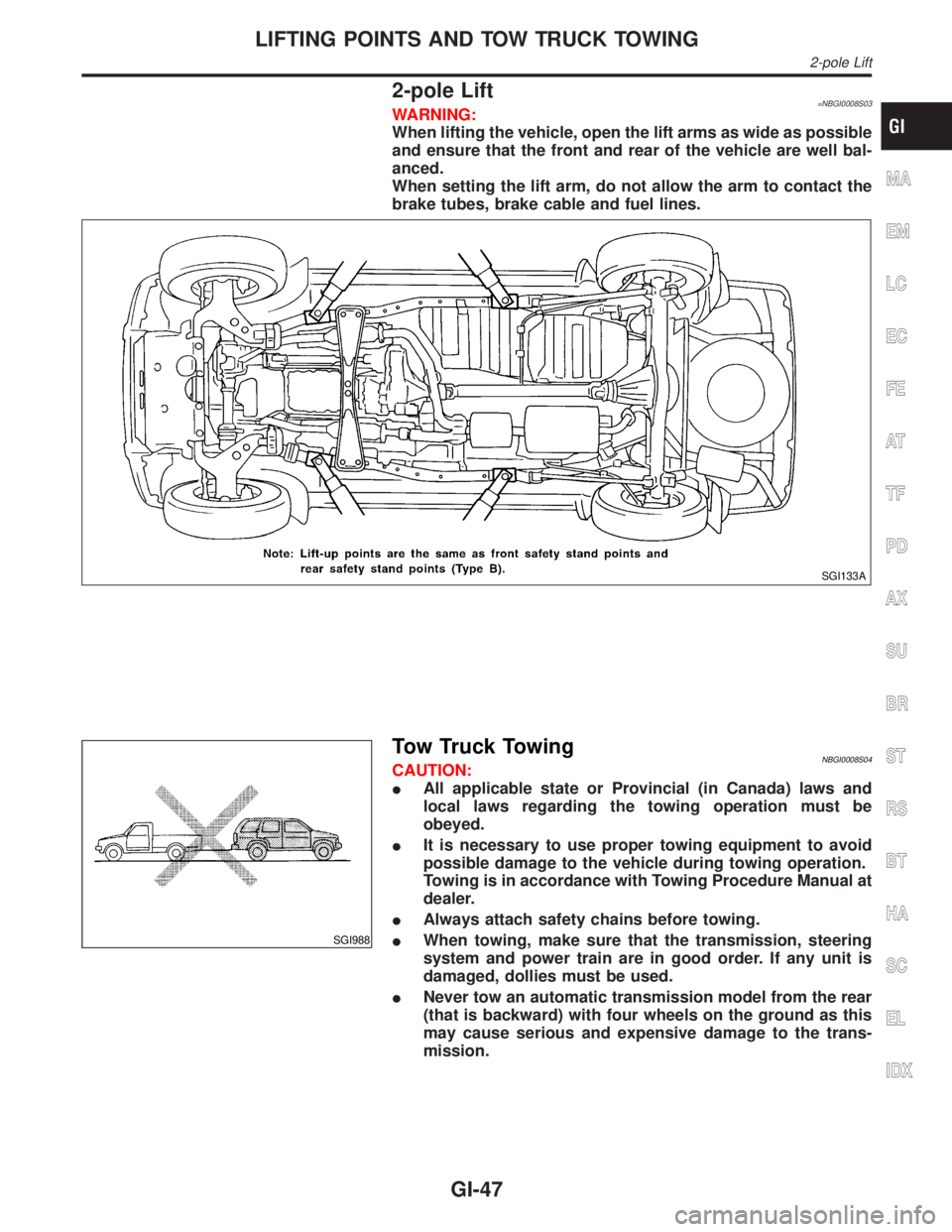
2-pole Lift=NBGI0008S03WARNING:
When lifting the vehicle, open the lift arms as wide as possible
and ensure that the front and rear of the vehicle are well bal-
anced.
When setting the lift arm, do not allow the arm to contact the
brake tubes, brake cable and fuel lines.
SGI133A
SGI988
Tow Truck TowingNBGI0008S04CAUTION:
IAll applicable state or Provincial (in Canada) laws and
local laws regarding the towing operation must be
obeyed.
IIt is necessary to use proper towing equipment to avoid
possible damage to the vehicle during towing operation.
Towing is in accordance with Towing Procedure Manual at
dealer.
IAlways attach safety chains before towing.
IWhen towing, make sure that the transmission, steering
system and power train are in good order. If any unit is
damaged, dollies must be used.
INever tow an automatic transmission model from the rear
(that is backward) with four wheels on the ground as this
may cause serious and expensive damage to the trans-
mission.
MA
EM
LC
EC
FE
AT
TF
PD
AX
SU
BR
ST
RS
BT
HA
SC
EL
IDX
LIFTING POINTS AND TOW TRUCK TOWING
2-pole Lift
GI-47
Page 1793 of 2395

SGI989
2WD MODELSNBGI0008S0402INFINITI recommends that vehicle be towed with the driving (rear)
wheels off the ground as illustrated.
CAUTION:
IWhen towing manual or automatic transmission models
with the front wheels on the ground: Turn the ignition key
to the OFF position and secure the steering wheel in a
straightahead position with a rope or similar device. Never
place the ignition key in the LOCK position. This will result
in damage to the steering lock mechanism.
IWhen towing manual transmission models with the rear
wheels on the ground or four wheels on the ground (if you
do not use towing dollies): Always release the parking
brake and move the transmission shift lever to the N (neu-
tral) position.
Observe the following restricted towing speeds and distances.
Manual transmission models:
ISpeed: Below 95 km/h (60 MPH)
IDistance: Less than 800 km (500 miles)
If the speed or distance must necessarily be greater, remove the
propeller shaft beforehand to prevent damage to the transmission.
SGI950
4WD MODELSNBGI0008S0403INFINITI recommends that a dolly or a flat bed truck be used as
illustrated when towing all-mode 4WD models.
LIFTING POINTS AND TOW TRUCK TOWING
Tow Truck Towing (Cont'd)
GI-48
Page 1795 of 2395
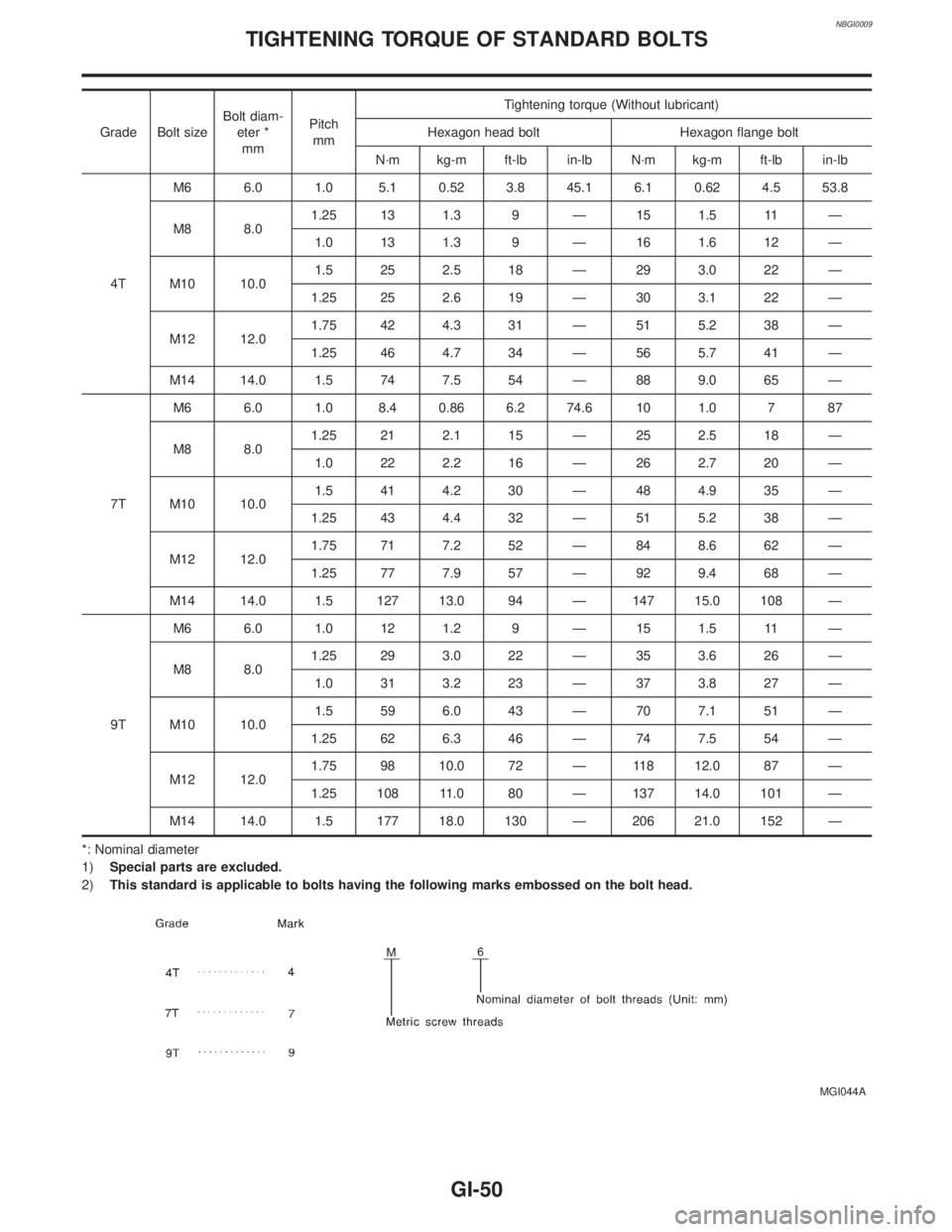
NBGI0009
Grade Bolt sizeBolt diam-
eter *
mmPitch
mmTightening torque (Without lubricant)
Hexagon head bolt Hexagon flange bolt
N´m kg-m ft-lb in-lb N´m kg-m ft-lb in-lb
4TM6 6.0 1.0 5.1 0.52 3.8 45.1 6.1 0.62 4.5 53.8
M8 8.01.25 13 1.3 9 Ð 15 1.5 11 Ð
1.0 13 1.3 9 Ð 16 1.6 12 Ð
M10 10.01.5 25 2.5 18 Ð 29 3.0 22 Ð
1.25 25 2.6 19 Ð 30 3.1 22 Ð
M12 12.01.75 42 4.3 31 Ð 51 5.2 38 Ð
1.25 46 4.7 34 Ð 56 5.7 41 Ð
M14 14.0 1.5 74 7.5 54 Ð 88 9.0 65 Ð
7TM6 6.0 1.0 8.4 0.86 6.2 74.6 10 1.0 7 87
M8 8.01.25 21 2.1 15 Ð 25 2.5 18 Ð
1.0 22 2.2 16 Ð 26 2.7 20 Ð
M10 10.01.5 41 4.2 30 Ð 48 4.9 35 Ð
1.25 43 4.4 32 Ð 51 5.2 38 Ð
M12 12.01.75 71 7.2 52 Ð 84 8.6 62 Ð
1.25 77 7.9 57 Ð 92 9.4 68 Ð
M14 14.0 1.5 127 13.0 94 Ð 147 15.0 108 Ð
9TM6 6.0 1.0 12 1.2 9 Ð 15 1.5 11 Ð
M8 8.01.25 29 3.0 22 Ð 35 3.6 26 Ð
1.0 31 3.2 23 Ð 37 3.8 27 Ð
M10 10.01.5 59 6.0 43 Ð 70 7.1 51 Ð
1.25 62 6.3 46 Ð 74 7.5 54 Ð
M12 12.01.75 98 10.0 72 Ð 118 12.0 87 Ð
1.25 108 11.0 80 Ð 137 14.0 101 Ð
M14 14.0 1.5 177 18.0 130 Ð 206 21.0 152 Ð
*: Nominal diameter
1)Special parts are excluded.
2)This standard is applicable to bolts having the following marks embossed on the bolt head.
MGI044A
TIGHTENING TORQUE OF STANDARD BOLTS
GI-50
Page 1801 of 2395
Supplemental Restraint System (SRS) ªAIR
BAGº and ªSEAT BELT PRE-TENSIONERº
NBHA0001The Supplemental Restraint System such as ªAIR BAGº and ªSEAT BELT PRE-TENSIONERº used along with
a seat belt, helps to reduce the risk or severity of injury to the driver and front passenger for certain types of
collision. The SRS system composition which is available to INFINITI QX4 is as follows:
IFor a frontal collision
The Supplemental Restraint System consists of driver air bag module (located in the center of the steer-
ing wheel), front passenger air bag module (located on the instrument panel on passenger side), seat belt
pre-tensioners, a diagnosis sensor unit, warning lamp, wiring harness and spiral cable.
IFor a side collision
The Supplemental Restraint System consists of front side air bag module (located in the outer side of front
seat), satellite sensor, diagnosis sensor unit (one of components of air bags for a frontal collision), wiring
harness, warning lamp (one of components of air bags for a frontal collision).
Information necessary to service the system safely is included in theRS sectionof this Service Manual.
WARNING:
ITo avoid rendering the SRS inoperative, which could increase the risk of personal injury or death
in the event of a collision which would result in air bag inflation, all maintenance must be performed
by an authorized INFINITI dealer.
IImproper maintenance, including incorrect removal and installation of the SRS, can lead to per-
sonal injury caused by unintentional activation of the system. For removal of Spiral Cable and Air
Bag Module, see the RS section.
IDo not use electrical test equipment on any circuit related to the SRS unless instructed to in this
Service Manual. Spiral cable and wiring harnesses covered with yellow insulation tape either just
before the harness connectors or for the complete harness are related to the SRS.
Precautions for Working with HFC-134a
(R-134a)
NBHA0002WARNING:
ICFC-12 (R-12) refrigerant and HFC-134a (R-134a) refrigerant are not compatible. If the refrigerants
are mixed and compressor failure is likely to occur, refer to ªCONTAMINATED REFRIGERANTº
below. To determine the purity of HFC-134a (R-134a) in the vehicle and recovery tank, use Refrig-
erant Recovery/Recycling Recharging equipment (ACR4) (J-39500-INF) and Refrigerant Identifier.
IUse only specified lubricant for the HFC-134a (R-134a) A/C system and HFC-134a (R-134a) compo-
nents. If lubricant other than that specified is used, compressor failure is likely to occur.
IThe specified HFC-134a (R-134a) lubricant rapidly absorbs moisture from the atmosphere. The fol-
lowing handling precautions must be observed:
a) When removing refrigerant components from a vehicle, immediately cap (seal) the component to
minimize the entry of moisture from the atmosphere.
b) When installing refrigerant components to a vehicle, do not remove the caps (unseal) until just
before connecting the components. Connect all refrigerant loop components as quickly as pos-
sible to minimize the entry of moisture into system.
c) Only use the specified lubricant from a sealed container. Immediately reseal containers of lubri-
cant. Without proper sealing, lubricant will become moisture saturated and should not be used.
d) Avoid breathing A/C refrigerant and lubricant vapor or mist. Exposure may irritate eyes, nose and
throat. Remove R-134a from the A/C system, using certified service equipment meeting require-
ments of SAE J2210 (R-134a recycling equipment), or J2209 (R-134a recovery equipment). If acci-
dental system discharge occurs, ventilate work area before resuming service. Additional health and
safety information may be obtained from refrigerant and lubricant manufacturers.
e) Do not allow lubricant (Nissan A/C System Oil Type S) to come in contact with styrofoam parts.
Damage may result.
CONTAMINATED REFRIGERANTNBHA0002S01If a refrigerant other than pure R-134a is identified in a vehicle, your options are:
IExplain to the customer that environmental regulations prohibit the release of contaminated refrigerant into
the atmosphere.
IExplain that recovery of the contaminated refrigerant could damage your service equipment and refriger-
ant supply.
PRECAUTIONS
Supplemental Restraint System (SRS) ªAIR BAGº and ªSEAT BELT PRE-TENSIONERº
HA-2
Page 1805 of 2395
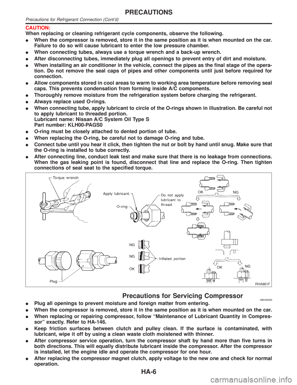
CAUTION:
When replacing or cleaning refrigerant cycle components, observe the following.
IWhen the compressor is removed, store it in the same position as it is when mounted on the car.
Failure to do so will cause lubricant to enter the low pressure chamber.
IWhen connecting tubes, always use a torque wrench and a back-up wrench.
IAfter disconnecting tubes, immediately plug all openings to prevent entry of dirt and moisture.
IWhen installing an air conditioner in the vehicle, connect the pipes as the final stage of the opera-
tion. Do not remove the seal caps of pipes and other components until just before required for
connection.
IAllow components stored in cool areas to warm to working area temperature before removing seal
caps. This prevents condensation from forming inside A/C components.
IThoroughly remove moisture from the refrigeration system before charging the refrigerant.
IAlways replace used O-rings.
IWhen connecting tube, apply lubricant to circle of the O-rings shown in illustration. Be careful not
to apply lubricant to threaded portion.
Lubricant name: Nissan A/C System Oil Type S
Part number: KLH00-PAGS0
IO-ring must be closely attached to dented portion of tube.
IWhen replacing the O-ring, be careful not to damage O-ring and tube.
IConnect tube until you hear it click, then tighten the nut or bolt by hand until snug. Make sure that
the O-ring is installed to tube correctly.
IAfter connecting line, conduct leak test and make sure that there is no leakage from connections.
When the gas leaking point is found, disconnect that line and replace the O-ring. Then tighten
connections of seal seat to the specified torque.
RHA861F
Precautions for Servicing CompressorNBHA0005IPlug all openings to prevent moisture and foreign matter from entering.
IWhen the compressor is removed, store it in the same position as it is when mounted on the car.
IWhen replacing or repairing compressor, follow ªMaintenance of Lubricant Quantity in Compres-
sorº exactly. Refer to HA-146.
IKeep friction surfaces between clutch and pulley clean. If the surface is contaminated, with
lubricant, wipe it off by using a clean waste cloth moistened with thinner.
IAfter compressor service operation, turn the compressor shaft by hand more than five turns in
both directions. This will equally distribute lubricant inside the compressor. After the compressor
is installed, let the engine idle and operate the compressor for one hour.
IAfter replacing the compressor magnet clutch, apply voltage to the new one and check for normal
operation.
PRECAUTIONS
Precautions for Refrigerant Connection (Cont'd)
HA-6
Page 1809 of 2395
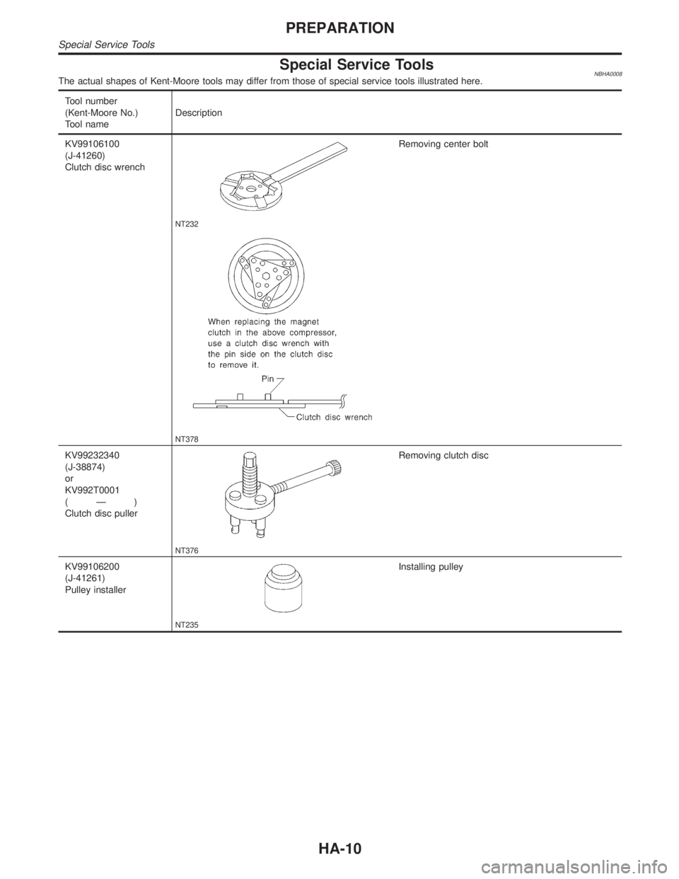
Special Service ToolsNBHA0008The actual shapes of Kent-Moore tools may differ from those of special service tools illustrated here.
Tool number
(Kent-Moore No.)
Tool nameDescription
KV99106100
(J-41260)
Clutch disc wrench
NT232
Removing center bolt
NT378
KV99232340
(J-38874)
or
KV992T0001
(Ð)
Clutch disc puller
NT376
Removing clutch disc
KV99106200
(J-41261)
Pulley installer
NT235
Installing pulley
PREPARATION
Special Service Tools
HA-10
Page 1817 of 2395
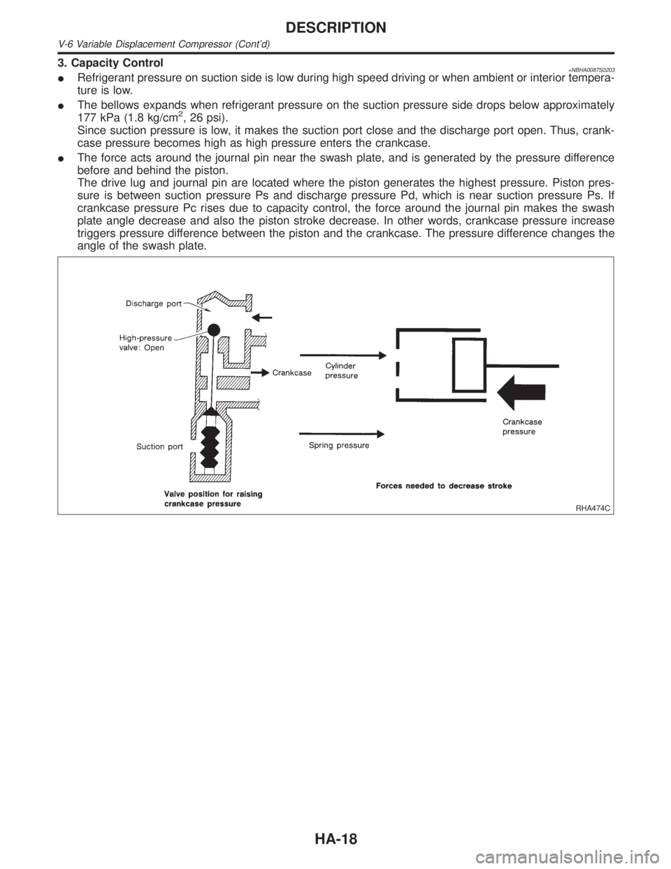
3. Capacity Control=NBHA0087S0203IRefrigerant pressure on suction side is low during high speed driving or when ambient or interior tempera-
ture is low.
IThe bellows expands when refrigerant pressure on the suction pressure side drops below approximately
177 kPa (1.8 kg/cm
2, 26 psi).
Since suction pressure is low, it makes the suction port close and the discharge port open. Thus, crank-
case pressure becomes high as high pressure enters the crankcase.
IThe force acts around the journal pin near the swash plate, and is generated by the pressure difference
before and behind the piston.
The drive lug and journal pin are located where the piston generates the highest pressure. Piston pres-
sure is between suction pressure Ps and discharge pressure Pd, which is near suction pressure Ps. If
crankcase pressure Pc rises due to capacity control, the force around the journal pin makes the swash
plate angle decrease and also the piston stroke decrease. In other words, crankcase pressure increase
triggers pressure difference between the piston and the crankcase. The pressure difference changes the
angle of the swash plate.
RHA474C
DESCRIPTION
V-6 Variable Displacement Compressor (Cont'd)
HA-18
Page 1869 of 2395

RHA463GA
RHA334HA
8. Check AUTO ModeNBHA0019S02081. Press AUTO switch.
2. Display should indicate AUTO (no ECON).
Confirm that the compressor clutch engages (audio or visual
inspection).
(Discharge air and blower speed will depend on ambient, in-
vehicle and set temperatures.)
If NG, go to trouble diagnosis procedure for A/C system (HA-71),
then if necessary, trouble diagnosis procedure for magnet clutch
(HA-104).
SHA286HA
9. Check Ambient Display (With Navigation System)NBHA0019S02091. Press AUTO switch.
2. Press AMB switch.
3. Display should show the outside (ambient) temperature for
approximately 5 seconds.
If NG, go to trouble diagnosis procedure for multiplex communica-
tion circuit (HA-142).
If all operational check are OK (symptom can not be duplicated),
go to ªIncident Simulation Testsº (GI section) and perform tests as
outlined to simulate driving conditions environment. If symptom
appears, refer to ªSymptom Tableº (HA-65) and perform applicable
trouble diagnosis procedures.
TROUBLE DIAGNOSES
Operational Check (Cont'd)
HA-70
Page 1928 of 2395

With Navigation SystemNBHA0103S0102
RHA887H
*1: HA-72 *2: HA-66 *3: HA-45
RHA050G
Ambient Sensor Circuit
COMPONENT DESCRIPTIONNBHA0039The ambient sensor is attached in front of the driver's side con-
denser. It detects ambient temperature and converts it into a resis-
tance value which is then input into the auto amplifier.
AMBIENT TEMPERATURE INPUT PROCESSNBHA0040The automatic amplifier includes a ªprocessing circuitº for the ambi-
ent sensor input. However, when the temperature detected by the
ambient sensor increases quickly, the processing circuit retards the
auto amp. function. It only allows the auto amp. to recognize an
ambient temperature increase of 0.33ÉC (0.6ÉF) per 100 seconds.
As an example, consider stopping for a cup of coffee after high
speed driving. Although the actual ambient temperature has not
changed, the temperature detected by the ambient sensor will
increase. This is because the heat from the engine compartment
can radiate to the front grille area, location of the ambient sensor.
GI
MA
EM
LC
EC
FE
AT
TF
PD
AX
SU
BR
ST
RS
BT
SC
EL
IDX
TROUBLE DIAGNOSES
ECON (ECONOMY) Mode (Cont'd)
HA-129