service INFINITI QX4 2001 Factory Workshop Manual
[x] Cancel search | Manufacturer: INFINITI, Model Year: 2001, Model line: QX4, Model: INFINITI QX4 2001Pages: 2395, PDF Size: 43.2 MB
Page 383 of 2395

DRIVE SHAFT=NBAX0033
Drive shaft joint typeFinal drive sideTS82F
Wheel sideZF100
Fixed joint axial end play limit 1 mm (0.04 in)
Diameter Wheel side (D
1)29.0 mm (1.142 in)
GreaseQualityNissan genuine grease or equivalent
Specified amount of greaseFinal drive side 95 - 105 g (3.35 - 3.70 oz)
Wheel side 135 - 145 g (4.76 - 5.11 oz)
Drive shaft axial end play0.45 mm (0.0177 in) or less
Boot lengthFinal drive side (L
1) 95 - 97 mm (3.74 - 3.82 in)
Wheel side (L
2) 96 - 98 mm (3.78 - 3.86 in)
SAX001
Drive Shaft End Snap RingNBAX0033S01
Thickness mm (in) Part No. Thickness mm (in) Part No.
1.1 (0.043)
1.3 (0.051)
1.5 (0.059)
1.7 (0.067)39253-88G10
39253-88G11
39253-88G12
39253-88G131.9 (0.075)
2.1 (0.083)
2.3 (0.091)39253-88G14
39253-88G15
39253-88G16
FRONT AXLE
Service Data and Specifications (SDS) (Cont'd)
AX-16
Page 384 of 2395
SBR686C
Precautions
PRECAUTIONSNBAX0023IWhen installing rubber parts, final tightening must be car-
ried out under unladen condition* with tires on ground.
*Fuel, radiator coolant and engine oil full. Spare tire, jack,
hand tools and mats in designated positions.
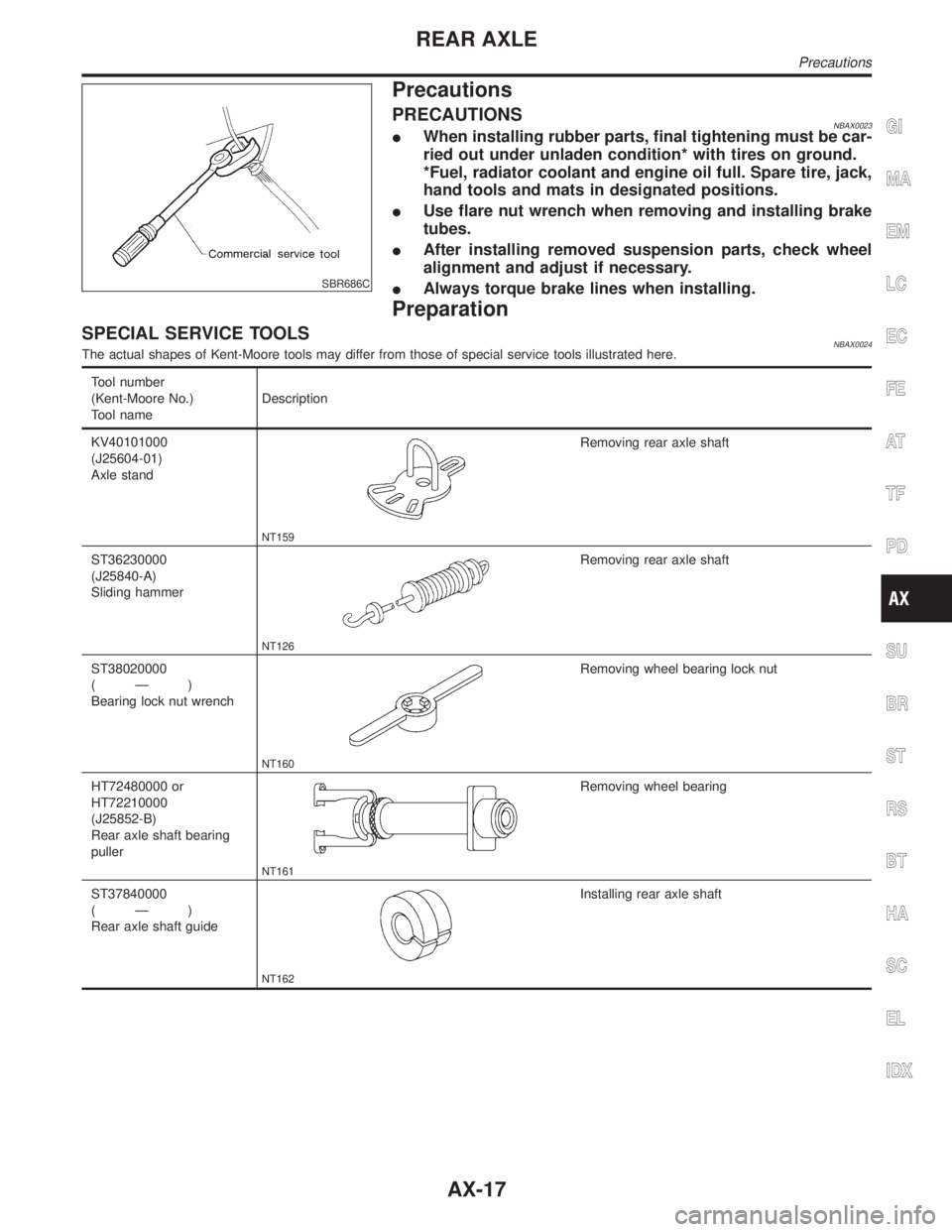
IUse flare nut wrench when removing and installing brake
tubes.
IAfter installing removed suspension parts, check wheel
alignment and adjust if necessary.
IAlways torque brake lines when installing.
Preparation
SPECIAL SERVICE TOOLSNBAX0024The actual shapes of Kent-Moore tools may differ from those of special service tools illustrated here.
Tool number
(Kent-Moore No.)
Tool nameDescription
KV40101000
(J25604-01)
Axle stand
NT159
Removing rear axle shaft
ST36230000
(J25840-A)
Sliding hammer
NT126
Removing rear axle shaft
ST38020000
(Ð)
Bearing lock nut wrench
NT160
Removing wheel bearing lock nut
HT72480000 or
HT72210000
(J25852-B)
Rear axle shaft bearing
puller
NT161
Removing wheel bearing
ST37840000
(Ð)
Rear axle shaft guide
NT162
Installing rear axle shaft
GI
MA
EM
LC
EC
FE
AT
TF
PD
SU
BR
ST
RS
BT
HA
SC
EL
IDX
REAR AXLE
Precautions
AX-17
Page 385 of 2395
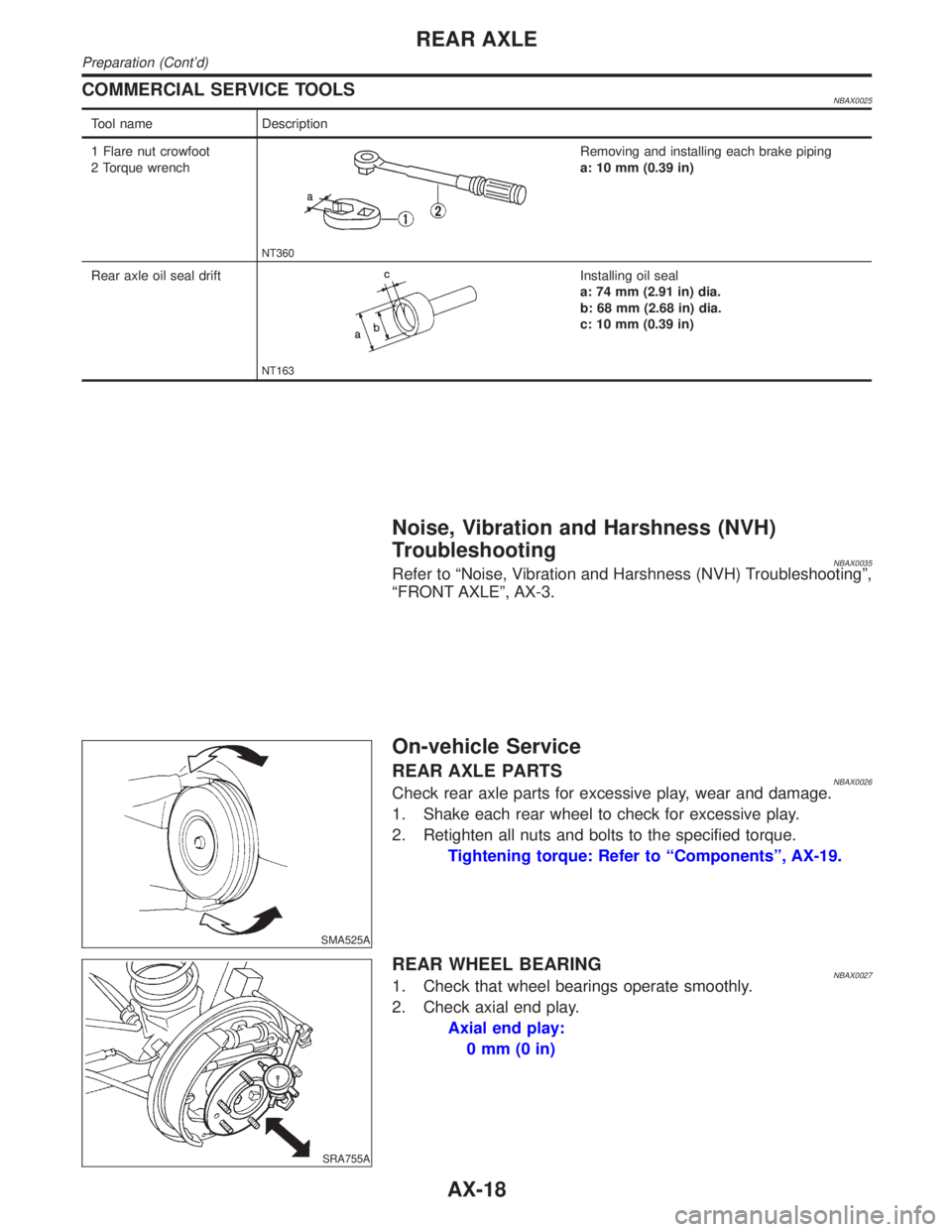
COMMERCIAL SERVICE TOOLSNBAX0025
Tool name Description
1 Flare nut crowfoot
2 Torque wrench
NT360
Removing and installing each brake piping
a: 10 mm (0.39 in)
Rear axle oil seal drift
NT163
Installing oil seal
a: 74 mm (2.91 in) dia.
b: 68 mm (2.68 in) dia.
c: 10 mm (0.39 in)
Noise, Vibration and Harshness (NVH)
Troubleshooting
NBAX0035Refer to ªNoise, Vibration and Harshness (NVH) Troubleshootingº,
ªFRONT AXLEº, AX-3.
SMA525A
On-vehicle Service
REAR AXLE PARTSNBAX0026Check rear axle parts for excessive play, wear and damage.
1. Shake each rear wheel to check for excessive play.
2. Retighten all nuts and bolts to the specified torque.
Tightening torque: Refer to ªComponentsº, AX-19.
SRA755A
REAR WHEEL BEARINGNBAX00271. Check that wheel bearings operate smoothly.
2. Check axial end play.
Axial end play:
0mm(0in)
REAR AXLE
Preparation (Cont'd)
AX-18
Page 389 of 2395
SRA763A
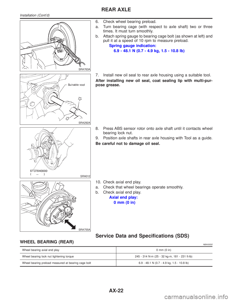
6. Check wheel bearing preload.
a. Turn bearing cage (with respect to axle shaft) two or three
times. It must turn smoothly.
b. Attach spring gauge to bearing cage bolt (as shown at left) and
pull it at a speed of 10 rpm to measure preload.
Spring gauge indication:
6.9 - 48.1 N (0.7 - 4.9 kg, 1.5 - 10.8 lb)
SRA292A
7. Install new oil seal to rear axle housing using a suitable tool.
After installing new oil seal, coat sealing lip with multi-pur-
pose grease.
SRA012
8. Press ABS sensor rotor onto axle shaft until it contacts wheel
bearing lock nut.
9. Position axle shafts in rear axle housing with Tool as a guide.
Be careful not to damage oil seal.
SRA755A
10. Check axial end play.
a. Check that wheel bearings operate smoothly.
b. Check axial end play.
Axial end play:
0mm(0in)
Service Data and Specifications (SDS)
WHEEL BEARING (REAR)NBAX0032
Wheel bearing axial end play0mm(0in)
Wheel bearing lock nut tightening torque 245 - 314 N´m (25 - 32 kg-m, 181 - 231 ft-lb)
Wheel bearing preload measured at bearing cage bolt 6.9 - 48.1 N (0.7 - 4.9 kg, 1.5 - 10.8 lb)
REAR AXLE
Installation (Cont'd)
AX-22
Page 390 of 2395

BRAKE SYSTEM
SECTION
BR
CONTENTS
PRECAUTIONS...............................................................3
Supplemental Restraint System (SRS)²AIR
BAG²and²SEAT BELT PRE-TENSIONER²...............3
Precautions for Brake System .....................................3
Wiring Diagrams and Trouble Diagnoses....................4
PREPARATION...............................................................5
Special Service Tools ..................................................5
Commercial Service Tools ...........................................5
NOISE, VIBRATION AND HARSHNESS (NVH)
TROUBLESHOOTING.....................................................6
NVH Troubleshooting Chart.........................................6
ON-VEHICLE SERVICE..................................................7
Checking Brake Fluid Level.........................................7
Checking Brake Line ...................................................7
Changing Brake Fluid ..................................................7
Bleeding Brake System ...............................................8
BRAKE HYDRAULIC LINE.............................................9
Hydraulic Circuit...........................................................9
Removal .....................................................................10
Inspection...................................................................10
Installation ..................................................................10
PROPORTIONING VALVE (2WD)................................ 11
Inspection................................................................... 11
Removal and Installation (Built-in type)..................... 11
LOAD SENSING VALVE (4WD)...................................12
Inspection...................................................................12
Removal and Installation ...........................................12
BRAKE PEDAL AND BRACKET..................................14
Removal and Installation ...........................................14
Inspection...................................................................14
Adjustment .................................................................14
MASTER CYLINDER.....................................................16
Removal .....................................................................16
Disassembly...............................................................16
Inspection...................................................................17
Assembly ...................................................................17
Installation ..................................................................18
BRAKE BOOSTER........................................................19
On-vehicle Service.....................................................19OPERATING CHECK...............................................19
AIRTIGHT CHECK...................................................19
Removal .....................................................................19
Inspection...................................................................19
OUTPUT ROD LENGTH CHECK..............................19
Installation ..................................................................20
VACUUM PIPING...........................................................21
Vacuum Hose ............................................................21
Removal and Installation ...........................................21
Inspection...................................................................21
HOSES AND CONNECTORS...................................21
CHECK VALVE........................................................21
FRONT DISC BRAKE...................................................22
Components...............................................................22
Pad Replacement ......................................................22
Removal .....................................................................23
Disassembly...............................................................24
Inspection...................................................................24
CALIPER.................................................................24
ROTOR...................................................................24
Assembly ...................................................................25
Installation ..................................................................25
Brake Burnishing Procedure......................................25
REAR DRUM BRAKE...................................................26
Components...............................................................26
Removal .....................................................................26
Inspection...................................................................27
WHEEL CYLINDER..................................................27
Wheel Cylinder Overhaul...........................................28
Inspection...................................................................28
DRUM.....................................................................28
LINING....................................................................28
Installation ..................................................................28
PARKING BRAKE CONTROL......................................30
Components...............................................................30
Removal and Installation ...........................................30
Inspection...................................................................30
Adjustment .................................................................31
GI
MA
EM
LC
EC
FE
AT
TF
PD
AX
SU
ST
RS
BT
HA
SC
EL
IDX
Page 391 of 2395
ABS
DESCRIPTION...............................................................32
Purpose......................................................................32
Operation ...................................................................32
ABS Hydraulic Circuit ................................................32
System Components .................................................33
System Description ....................................................33
SENSOR.................................................................33
CONTROL UNIT (BUILT-IN ABS ACTUATOR AND
ELECTRIC UNIT)
.....................................................33
ABS ACTUATOR AND ELECTRIC UNIT....................33
G SENSOR (4WD MODELS ONLY)..........................34
Component Parts and Harness Connector
Location .....................................................................35
Schematic ..................................................................36
Wiring Diagram - ABS - .............................................37
ON BOARD DIAGNOSTIC SYSTEM
DESCRIPTION...............................................................41
Self-diagnosis ............................................................41
FUNCTION..............................................................41
SELF-DIAGNOSIS PROCEDURE..............................41
HOW TO READ SELF-DIAGNOSTIC RESULTS
(MALFUNCTION CODES)
........................................42
HOW TO ERASE SELF-DIAGNOSTIC RESULTS
(MALFUNCTION CODES)
........................................42
CONSULT-II ...............................................................43
CONSULT-II APPLICATION TO ABS..........................43
ECU (ABS CONTROL UNIT) PART NUMBER
MODE
.....................................................................43
CONSULT-II Inspection Procedure............................44
SELF-DIAGNOSIS PROCEDURE..............................44
SELF-DIAGNOSTIC RESULTS MODE.......................45
DATA MONITOR PROCEDURE................................46
ACTIVE TEST PROCEDURE....................................47
DATA MONITOR MODE...........................................48
ACTIVE TEST MODE...............................................48
TROUBLE DIAGNOSIS - INTRODUCTION..................49
How to Perform Trouble Diagnoses for Quick
and Accurate Repair ..................................................49
INTRODUCTION......................................................49
TROUBLE DIAGNOSIS - BASIC INSPECTION...........50
Preliminary Check......................................................50
Ground Circuit Check ................................................53
ABS ACTUATOR AND ELECTRIC UNIT GROUND.....53
TROUBLE DIAGNOSIS - GENERAL
DESCRIPTION...............................................................54
Malfunction Code/Symptom Chart.............................54
TROUBLE DIAGNOSES FOR SELF-DIAGNOSTIC
ITEMS.............................................................................56Wheel Sensor or Rotor ..............................................56
DIAGNOSTIC PROCEDURE.....................................56
ABS Actuator Solenoid Valve or Solenoid Valve
Relay ..........................................................................59
DIAGNOSTIC PROCEDURE.....................................59
Motor Relay or Motor.................................................61
DIAGNOSTIC PROCEDURE.....................................61
Low Voltage ...............................................................63
DIAGNOSTIC PROCEDURE.....................................63
G Sensor and Circuit .................................................65
DIAGNOSTIC PROCEDURE.....................................65
ELECTRICAL COMPONENT INSPECTION................67
Control Unit ................................................................68
DIAGNOSTIC PROCEDURE.....................................68
TROUBLE DIAGNOSES FOR SYMPTOMS.................69
1. ABS Works Frequently ..........................................69
2. Unexpected Pedal Action ......................................69
3. Long Stopping Distance ........................................70
4. ABS Does Not Work ..............................................71
5. Pedal Vibration and Noise.....................................71
6. Warning Lamp Does Not Come On When
Ignition Switch Is Turned On .....................................72
7. Warning Lamp Stays On When Ignition Switch
Is Turned On ..............................................................74
8. Vehicle Vibrates Excessively When ABS Is
Operating ...................................................................77
REMOVAL AND INSTALLATION.................................80
Front Wheel Sensor...................................................80
Rear Wheel Sensor ...................................................80
Front Sensor Rotor ....................................................81
REMOVAL...............................................................81
INSTALLATION........................................................81
Rear Sensor Rotor.....................................................81
REMOVAL...............................................................81
INSTALLATION........................................................81
G Sensor....................................................................81
ABS Actuator and Electric Unit..................................82
REMOVAL...............................................................82
INSTALLATION........................................................82
SERVICE DATA AND SPECIFICATIONS (SDS).........83
General Specifications ...............................................83
Disc Brake .................................................................83
Drum Brake................................................................83
Brake Pedal ...............................................................83
Parking Brake Control ...............................................84
CONTENTS(Cont'd)
BR-2
Page 392 of 2395
Supplemental Restraint System (SRS) ªAIR
BAGº and ªSEAT BELT PRE-TENSIONERº
NBBR0001The Supplemental Restraint System such as ªAIR BAGº and ªSEAT BELT PRE-TENSIONERº used along with
a seat belt, helps to reduce the risk or severity of injury to the driver and front passenger for certain types of
collision. The SRS system composition which is available to INFINITI QX4 is as follows:
IFor a frontal collision
The Supplemental Restraint System consists of driver air bag module (located in the center of the steer-
ing wheel), front passenger air bag module (located on the instrument panel on passenger side), seat belt
pre-tensioners, a diagnosis sensor unit, warning lamp, wiring harness and spiral cable.
IFor a side collision
The Supplemental Restraint System consists of side air bag module (located in the outer side of front seat),
satellite sensor, diagnosis sensor unit (one of components of air bags for a frontal collision), wiring harness,
warning lamp (one of components of air bags for a frontal collision).
Information necessary to service the system safely is included in theRS sectionof this Service Manual.
WARNING:
ITo avoid rendering the SRS inoperative, which could increase the risk of personal injury or death
in the event of a collision which would result in air bag inflation, all maintenance must be performed
by an authorized INFINITI dealer.
IImproper maintenance, including incorrect removal and installation of the SRS, can lead to per-
sonal injury caused by unintentional activation of the system. For removal of Spiral Cable and Air
Bag Module, see the RS section.
IDo not use electrical test equipment on any circuit related to the SRS unless instructed to in this
Service Manual. Spiral cable and wiring harnesses covered with yellow insulation tape either just
before the harness connectors or for the complete harness are related to the SRS.
SBR686C
Precautions for Brake SystemNBBR0002IUse brake fluid ªDOT 3º.
INever reuse drained brake fluid.
IBe careful not to splash brake fluid on painted areas; it
may cause paint damage. If brake fluid is splashed on
painted areas, wash it away with water immediately.
ITo clean master cylinder parts, disc brake caliper parts or
wheel cylinder parts, use clean brake fluid.
INever use mineral oils such as gasoline or kerosene. They
will ruin rubber parts of hydraulic system.
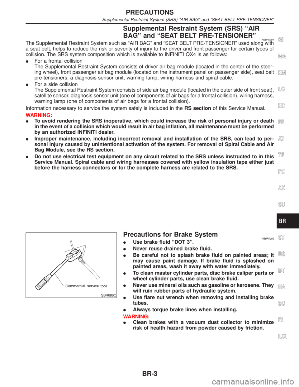
IUse flare nut wrench when removing and installing brake
tubes.
IAlways torque brake lines when installing.
WARNING:
IClean brakes with a vacuum dust collector to minimize
risk of health hazard from powder caused by friction.
GI
MA
EM
LC
EC
FE
AT
TF
PD
AX
SU
ST
RS
BT
HA
SC
EL
IDX
PRECAUTIONS
Supplemental Restraint System (SRS) ªAIR BAGº and ªSEAT BELT PRE-TENSIONERº
BR-3
Page 394 of 2395
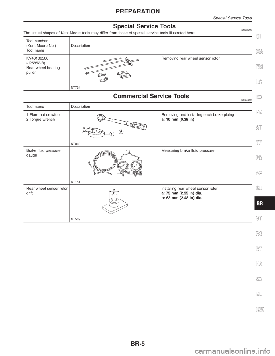
Special Service ToolsNBBR0004The actual shapes of Kent-Moore tools may differ from those of special service tools illustrated here.
Tool number
(Kent-Moore No.)
Tool nameDescription
KV40106500
(J25852-B)
Rear wheel bearing
puller
NT724
Removing rear wheel sensor rotor
Commercial Service ToolsNBBR0005
Tool name Description
1 Flare nut crowfoot
2 Torque wrench
NT360
Removing and installing each brake piping
a: 10 mm (0.39 in)
Brake fluid pressure
gauge
NT151
Measuring brake fluid pressure
Rear wheel sensor rotor
drift
NT509
Installing rear wheel sensor rotor
a: 75 mm (2.95 in) dia.
b: 63 mm (2.48 in) dia.
GI
MA
EM
LC
EC
FE
AT
TF
PD
AX
SU
ST
RS
BT
HA
SC
EL
IDX
PREPARATION
Special Service Tools
BR-5
Page 396 of 2395
SBR451D
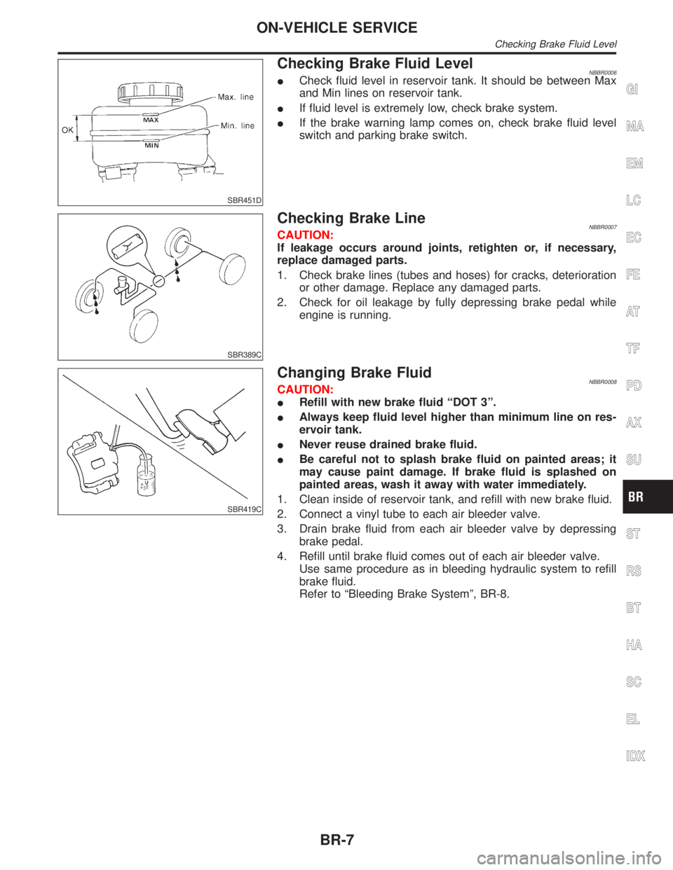
Checking Brake Fluid LevelNBBR0006ICheck fluid level in reservoir tank. It should be between Max
and Min lines on reservoir tank.
IIf fluid level is extremely low, check brake system.
IIf the brake warning lamp comes on, check brake fluid level
switch and parking brake switch.
SBR389C
Checking Brake LineNBBR0007CAUTION:
If leakage occurs around joints, retighten or, if necessary,
replace damaged parts.
1. Check brake lines (tubes and hoses) for cracks, deterioration
or other damage. Replace any damaged parts.
2. Check for oil leakage by fully depressing brake pedal while
engine is running.
SBR419C
Changing Brake FluidNBBR0008CAUTION:
IRefill with new brake fluid ªDOT 3º.
IAlways keep fluid level higher than minimum line on res-
ervoir tank.
INever reuse drained brake fluid.
IBe careful not to splash brake fluid on painted areas; it
may cause paint damage. If brake fluid is splashed on
painted areas, wash it away with water immediately.
1. Clean inside of reservoir tank, and refill with new brake fluid.
2. Connect a vinyl tube to each air bleeder valve.
3. Drain brake fluid from each air bleeder valve by depressing
brake pedal.
4. Refill until brake fluid comes out of each air bleeder valve.
Use same procedure as in bleeding hydraulic system to refill
brake fluid.
Refer to ªBleeding Brake Systemº, BR-8.
GI
MA
EM
LC
EC
FE
AT
TF
PD
AX
SU
ST
RS
BT
HA
SC
EL
IDX
ON-VEHICLE SERVICE
Checking Brake Fluid Level
BR-7
Page 397 of 2395

SBR995
Bleeding Brake System=NBBR0009CAUTION:
ICarefully monitor brake fluid level at master cylinder dur-
ing bleeding operation.
IIf master cylinder is suspected to have air inside, bleed air
from master cylinder first. Refer to ªInstallationº, ªMAS-
TER CYLINDERº, BR-18.
IFill reservoir with new brake fluid ªDOT 3º. Make sure it is
full at all times while bleeding air out of system.
IPlace a container under master cylinder to avoid spillage
of brake fluid.
ITurn ignition switch OFF and disconnect ABS actuator
and electric unit connectors or battery ground cable.
IBleed air in the following order.
1. LSV air bleeder (4WD)
2. Left rear brake
3. Right rear brake
4. Left front brake
5. Right front brake
SBR419C
1. Connect a transparent vinyl tube to air bleeder valve.
2. Fully depress brake pedal several times.
3. With brake pedal depressed, open air bleeder valve to release
air.
4. Close air bleeder valve.
5. Release brake pedal slowly.
6. Repeat steps 2. through 5. until clear brake fluid comes out of
air bleeder valve.
7. Tighten air bleeder valve.
:7-9N´m(0.7 - 0.9 kg-m, 61 - 78 in-lb)
ON-VEHICLE SERVICE
Bleeding Brake System
BR-8