service INFINITI QX4 2001 Factory Workshop Manual
[x] Cancel search | Manufacturer: INFINITI, Model Year: 2001, Model line: QX4, Model: INFINITI QX4 2001Pages: 2395, PDF Size: 43.2 MB
Page 408 of 2395

SBR002A
SBR365AA
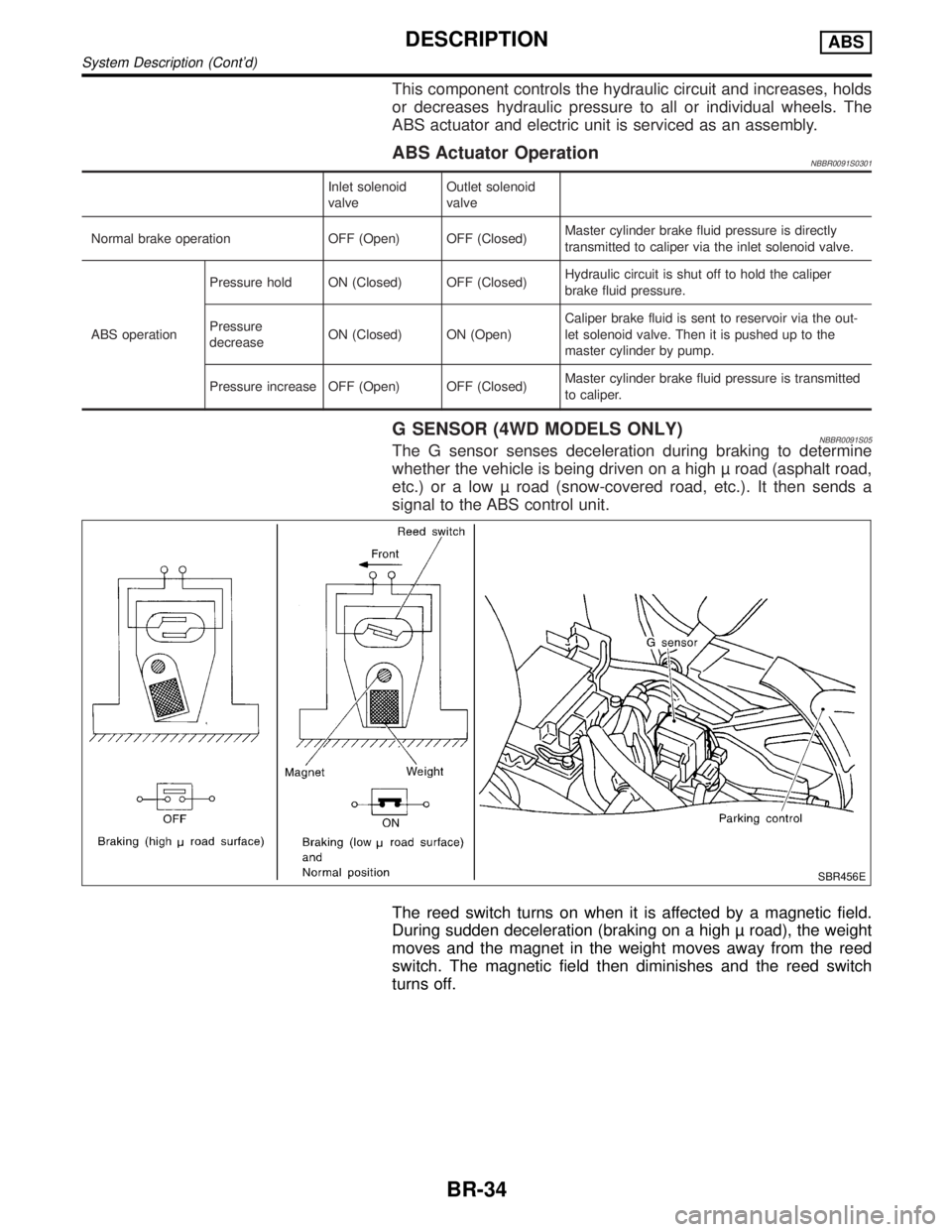
On-vehicle ServiceNBBR0024OPERATING CHECKNBBR0024S011. Depress brake pedal several times with engine off. After
exhausting vacuum, make sure there is no change in pedal
stroke.
2. Depress brake pedal, then start engine. If pedal goes down
slightly, operation is normal.
AIRTIGHT CHECKNBBR0024S021. Start engine, and stop it after one or two minutes. Depress
brake pedal several times slowly. Booster is airtight if pedal
stroke is less each time.
2. Depress brake pedal while engine is running, and stop engine
with pedal depressed. The pedal stroke should not change
after holding pedal down for30 seconds.
SBR368DA
RemovalNBBR0025CAUTION:
IBe careful not to splash brake fluid on painted areas; it
may cause paint damage. If brake fluid is splashed on
painted areas, wash it away with water immediately.
IBe careful not to deform or bend brake pipes, during
removal of booster.
SBR208E
InspectionNBBR0026OUTPUT ROD LENGTH CHECKNBBR0026S011. Apply vacuum of þ66.7 kPa (þ500 mmHg, þ19.69 inHg) to
brake booster with a hand vacuum pump.
2. Add preload of 19.6 N (2.0 kg, 4.4 lb) to output rod.
3. Check output rod length.
Specified length:
10.275 - 10.525 mm (0.4045 - 0.4144 in)
GI
MA
EM
LC
EC
FE
AT
TF
PD
AX
SU
ST
RS
BT
HA
SC
EL
IDX
BRAKE BOOSTER
On-vehicle Service
BR-19
Page 423 of 2395

This component controls the hydraulic circuit and increases, holds
or decreases hydraulic pressure to all or individual wheels. The
ABS actuator and electric unit is serviced as an assembly.
ABS Actuator OperationNBBR0091S0301
Inlet solenoid
valveOutlet solenoid
valve
Normal brake operation OFF (Open) OFF (Closed)Master cylinder brake fluid pressure is directly
transmitted to caliper via the inlet solenoid valve.
ABS operationPressure hold ON (Closed) OFF (Closed)Hydraulic circuit is shut off to hold the caliper
brake fluid pressure.
Pressure
decreaseON (Closed) ON (Open)Caliper brake fluid is sent to reservoir via the out-
let solenoid valve. Then it is pushed up to the
master cylinder by pump.
Pressure increase OFF (Open) OFF (Closed)Master cylinder brake fluid pressure is transmitted
to caliper.
G SENSOR (4WD MODELS ONLY)NBBR0091S05The G sensor senses deceleration during braking to determine
whether the vehicle is being driven on a high road (asphalt road,
etc.) or a low road (snow-covered road, etc.). It then sends a
signal to the ABS control unit.
SBR456E
The reed switch turns on when it is affected by a magnetic field.
During sudden deceleration (braking on a high road), the weight
moves and the magnet in the weight moves away from the reed
switch. The magnetic field then diminishes and the reed switch
turns off.
DESCRIPTIONABS
System Description (Cont'd)
BR-34
Page 438 of 2395

SEF233G
SEF234G
How to Perform Trouble Diagnoses for Quick
and Accurate Repair
NBBR0098INTRODUCTIONNBBR0098S01The ABS system has an electronic control unit to control major
functions. The control unit accepts input signals from sensors and
instantly drives the actuators. It is essential that both kinds of sig-
nals are proper and stable. It is also important to check for conven-
tional problems: such as air leaks in booster lines, lack of brake
fluid, or other problems with the brake system.
It is much more difficult to diagnose a problem that occurs intermit-
tently rather than continuously. Most intermittent problems are
caused by poor electric connections or faulty wiring. In this case,
careful checking of suspicious circuits may help prevent the
replacement of good parts.
A visual check only may not find the cause of the problems, so a
road test should be performed.
Before undertaking actual checks, take a few minutes to talk with
a customer who approaches with an ABS complaint. The customer
is a very good source of information on such problems; especially
intermittent ones. By talking to the customer, find out what symp-
toms are present and under what conditions they occur. Start your
diagnosis by looking for ªconventionalº problems first. This is one
of the best ways to troubleshoot brake problems on an ABS con-
trolled vehicle.
Also check related Service bulletins for information.
GI
MA
EM
LC
EC
FE
AT
TF
PD
AX
SU
ST
RS
BT
HA
SC
EL
IDX
TROUBLE DIAGNOSIS Ð INTRODUCTIONABS
How to Perform Trouble Diagnoses for Quick and Accurate Repair
BR-49
Page 440 of 2395

4 CHECK BRAKE BOOSTER OPERATION
Check brake booster for operation and air tightness.
Refer to ªOn-vehicle Serviceº, ªBRAKE BOOSTERº, BR-19.
SBR058C
Is brake booster airtight and functioning properly?
Ye s©GO TO 5.
No©Replace. GO TO 5.
5 CHECK BRAKE PAD AND ROTOR
Check brake pad and rotor.
Refer to (BR-22, BR-24).
SBR059C
Are brake pads and rotors functioning properly?
Ye s©GO TO 6.
No©Replace.
GI
MA
EM
LC
EC
FE
AT
TF
PD
AX
SU
ST
RS
BT
HA
SC
EL
IDX
TROUBLE DIAGNOSIS Ð BASIC INSPECTIONABS
Preliminary Check (Cont'd)
BR-51
Page 472 of 2395

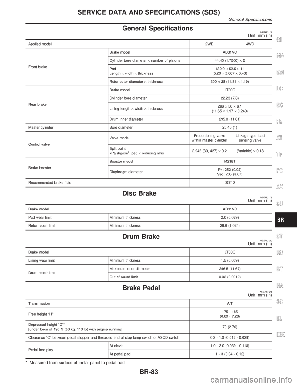
General SpecificationsNBBR0118Unit: mm (in)
Applied model2WD 4WD
Front brakeBrake model AD31VC
Cylinder bore diameter´number of pistons 44.45 (1.7500)´2
Pad
Length´width´thickness132.0´52.5´11
(5.20´2.067´0.43)
Rotor outer diameter´thickness 300´28 (11.81´1.10)
Rear brakeBrake model LT30C
Cylinder bore diameter 22.23 (7/8)
Lining length´width´thickness296´50´6.1
(11.65´1.97´0.240)
Drum inner diameter 295.0 (11.61)
Master cylinder Bore diameter 25.40 (1)
Control valveValve modelProportioning valve
within master cylinderLinkage type load
sensing valve
Split point
kPa (kg/cm
2, psi)´reducing ratio2,942 (30, 427)´0.2 (Variable)´0.18
Brake boosterBooster model M235T
Diaphragm diameterPri: 252 (9.92)
Sec: 205 (8.07)
Recommended brake fluidDOT 3
Disc BrakeNBBR0119Unit: mm (in)
Brake modelAD31VC
Pad wear limit Minimum thickness 2.0 (0.079)
Rotor repair limit Minimum thickness 26.0 (1.024)
Drum BrakeNBBR0120Unit: mm (in)
Brake modelLT30C
Lining wear limit Minimum thickness 1.5 (0.059)
Drum repair limitMaximum inner diameter 296.5 (11.67)
Out-of-round limit 0.03 (0.0012)
Brake PedalNBBR0121Unit: mm (in)
TransmissionA/T
Free height ªHº*175 - 185
(6.89 - 7.28)
Depressed height ªDº*
[under force of 490 N (50 kg, 110 lb) with engine running]70 (2.76)
Clearance ªCº between pedal stopper and threaded end of stop lamp switch or ASCD switch 0.3 - 1.0 (0.012 - 0.039)
Pedal free playAt clevis 1.0 - 3.0 (0.039 - 0.118)
At pedal pad1 - 3 (0.04 - 0.12)
*: Measured from surface of metal panel to pedal pad
GI
MA
EM
LC
EC
FE
AT
TF
PD
AX
SU
ST
RS
BT
HA
SC
EL
IDX
SERVICE DATA AND SPECIFICATIONS (SDS)
General Specifications
BR-83
Page 473 of 2395
![INFINITI QX4 2001 Factory Workshop Manual Parking Brake ControlNBBR0084Unit: notch
Control TypeCenter lever
Lever stroke
[under force of 196 N (20 kg, 44 lb)]6-8
Lever stroke when warning switch comes on 1 or less
SERVICE DATA AND SPECIFICATI INFINITI QX4 2001 Factory Workshop Manual Parking Brake ControlNBBR0084Unit: notch
Control TypeCenter lever
Lever stroke
[under force of 196 N (20 kg, 44 lb)]6-8
Lever stroke when warning switch comes on 1 or less
SERVICE DATA AND SPECIFICATI](/img/42/57027/w960_57027-472.png)
Parking Brake ControlNBBR0084Unit: notch
Control TypeCenter lever
Lever stroke
[under force of 196 N (20 kg, 44 lb)]6-8
Lever stroke when warning switch comes on 1 or less
SERVICE DATA AND SPECIFICATIONS (SDS)
Parking Brake Control
BR-84
Page 474 of 2395

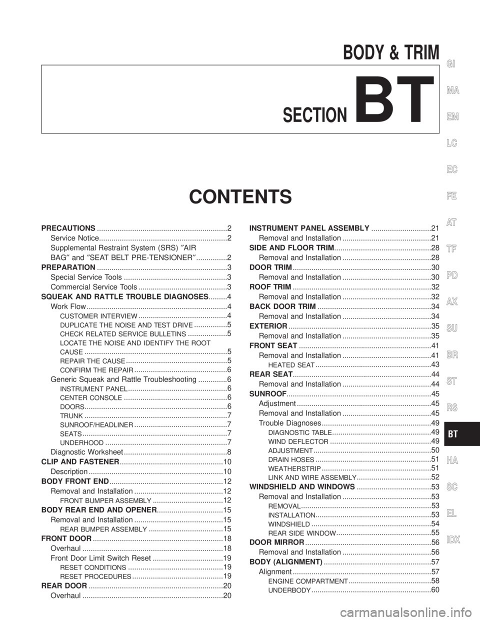
BODY & TRIM
SECTION
BT
CONTENTS
PRECAUTIONS...............................................................2
Service Notice..............................................................2
Supplemental Restraint System (SRS)²AIR
BAG²and²SEAT BELT PRE-TENSIONER²...............2
PREPARATION...............................................................3
Special Service Tools ..................................................3
Commercial Service Tools ...........................................3
SQUEAK AND RATTLE TROUBLE DIAGNOSES.........4
Work Flow ....................................................................4
CUSTOMER INTERVIEW...........................................4
DUPLICATE THE NOISE AND TEST DRIVE................5
CHECK RELATED SERVICE BULLETINS...................5
LOCATE THE NOISE AND IDENTIFY THE ROOT
CAUSE
.....................................................................5
REPAIR THE CAUSE.................................................5
CONFIRM THE REPAIR.............................................6
Generic Squeak and Rattle Troubleshooting ..............6
INSTRUMENT PANEL................................................6
CENTER CONSOLE..................................................6
DOORS.....................................................................6
TRUNK.....................................................................7
SUNROOF/HEADLINER.............................................7
SEATS......................................................................7
UNDERHOOD...........................................................7
Diagnostic Worksheet ..................................................8
CLIP AND FASTENER..................................................10
Description .................................................................10
BODY FRONT END.......................................................12
Removal and Installation ...........................................12
FRONT BUMPER ASSEMBLY..................................12
BODY REAR END AND OPENER................................15
Removal and Installation ...........................................15
REAR BUMPER ASSEMBLY....................................15
FRONT DOOR...............................................................18
Overhaul ....................................................................18
Front Door Limit Switch Reset ..................................19
RESET CONDITIONS..............................................19
RESET PROCEDURES............................................19
REAR DOOR.................................................................20
Overhaul ....................................................................20INSTRUMENT PANEL ASSEMBLY.............................21
Removal and Installation ...........................................21
SIDE AND FLOOR TRIM...............................................28
Removal and Installation ...........................................28
DOOR TRIM...................................................................30
Removal and Installation ...........................................30
ROOF TRIM...................................................................32
Removal and Installation ...........................................32
BACK DOOR TRIM.......................................................34
Removal and Installation ...........................................34
EXTERIOR.....................................................................35
Removal and Installation ...........................................35
FRONT SEAT................................................................41
Removal and Installation ...........................................41
HEATED SEAT........................................................43
REAR SEAT...................................................................44
Removal and Installation ...........................................44
SUNROOF......................................................................45
Adjustment .................................................................45
Removal and Installation ...........................................45
Trouble Diagnoses.....................................................49
DIAGNOSTIC TABLE................................................49
WIND DEFLECTOR.................................................49
ADJUSTMENT.........................................................50
DRAIN HOSES........................................................51
WEATHERSTRIP.....................................................51
LINK AND WIRE ASSEMBLY....................................52
WINDSHIELD AND WINDOWS....................................53
Removal and Installation ...........................................53
REMOVAL...............................................................53
INSTALLATION........................................................53
WINDSHIELD..........................................................54
REAR SIDE WINDOW..............................................55
DOOR MIRROR.............................................................56
Removal and Installation ...........................................56
BODY (ALIGNMENT)....................................................57
Alignment ...................................................................57
ENGINE COMPARTMENT........................................58
UNDERBODY..........................................................60
GI
MA
EM
LC
EC
FE
AT
TF
PD
AX
SU
BR
ST
RS
HA
SC
EL
IDX
Page 475 of 2395

Service NoticeNBBT0001IWhen removing or installing various parts, place a cloth or padding onto the vehicle body to prevent
scratches.
IHandle trim, molding, instruments, grille, etc. carefully during removing or installing. Be careful not to soil
or damage them.
IApply sealing compound where necessary when installing parts.
IWhen applying sealing compound, be careful that the sealing compound does not protrude from parts.
IWhen replacing any metal parts (for example body outer panel, members, etc.), be sure to take rust pre-
vention measures.
Supplemental Restraint System (SRS) ªAIR
BAGº and ªSEAT BELT PRE-TENSIONERº
NBBT0002The Supplemental Restraint System such as ªAIR BAGº and ªSEAT BELT PRE-TENSIONERº used along with
a seat belt, helps to reduce the risk or severity of injury to the driver and front passenger for certain types of
collision. The SRS system composition which is available to INFINITI QX4 is as follows:
IFor a frontal collision
The Supplemental Restraint System consists of driver air bag module (located in the center of the steer-
ing wheel), front passenger air bag module (located on the instrument panel on passenger side), seat belt
pre-tensioners, a diagnosis sensor unit, warning lamp, wiring harness and spiral cable.
IFor a side collision
The Supplemental Restraint System consists of side air bag module (located in the outer side of front seat),
satellite sensor, diagnosis sensor unit (one of components of air bags for a frontal collision), wiring harness,
warning lamp (one of components of air bags for a frontal collision).
Information necessary to service the system safely is included in theRS sectionof this Service Manual.
WARNING:
ITo avoid rendering the SRS inoperative, which could increase the risk of personal injury or death
in the event of a collision which would result in air bag inflation, all maintenance must be performed
by an authorized INFINITI dealer.
IImproper maintenance, including incorrect removal and installation of the SRS, can lead to per-
sonal injury caused by unintentional activation of the system. For removal of Spiral Cable and Air
Bag Module, see the RS section.
IDo not use electrical test equipment on any circuit related to the SRS unless instructed to in this
Service Manual. Spiral cable and wiring harnesses covered with yellow insulation tape either just
before the harness connectors or for the complete harness are related to the SRS.
PRECAUTIONS
Service Notice
BT-2
Page 476 of 2395

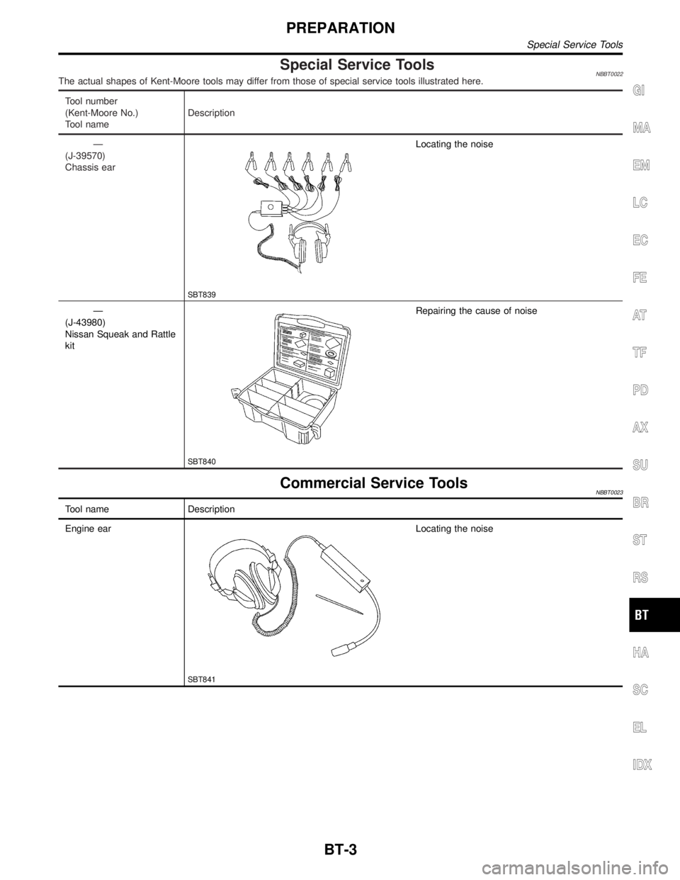
Special Service ToolsNBBT0022The actual shapes of Kent-Moore tools may differ from those of special service tools illustrated here.
Tool number
(Kent-Moore No.)
Tool nameDescription
Ð
(J-39570)
Chassis ear
SBT839
Locating the noise
Ð
(J-43980)
Nissan Squeak and Rattle
kit
SBT840
Repairing the cause of noise
Commercial Service ToolsNBBT0023
Tool name Description
Engine ear
SBT841
Locating the noise
GI
MA
EM
LC
EC
FE
AT
TF
PD
AX
SU
BR
ST
RS
HA
SC
EL
IDX
PREPARATION
Special Service Tools
BT-3
Page 477 of 2395

Work FlowNBBT0024
SBT842
CUSTOMER INTERVIEWNBBT0024S01Interview the customer, if possible, to determine the conditions that exist when the noise occurs. Use the
Diagnostic Worksheet during the interview to document the facts and conditions when the noise occurs and
any customer's comments; refer to BT-8. This information is necessary to duplicate the conditions that exist
when the noise occurs.
IThe customer may not be able to provide a detailed description or the location of the noise. Attempt to
obtain all the facts and conditions that exist when the noise occurs (or does not occur).
IIf there is more than one noise in the vehicle, be sure to diagnose and repair the noise that the customer
is concerned about. This can be accomplished by test driving the vehicle with the customer.
IAfter identifying the type of noise, isolate the noise in terms of its characteristics. The noise characteris-
tics are provided so the customer, service adviser and technician are all speaking the same language when
defining the noise.
ISqueak Ð (Like tennis shoes on a clean floor)
Squeak characteristics include the light contact/fast movement/brought on by road conditions/hard sur-
faces = higher pitch noise/softer surfaces = lower pitch noises/edge to surface = chirping
ICreak Ð (Like walking on an old wooden floor)
Creak characteristics include firm contact/slow movement/twisting with a rotational movement/pitch depen-
dent on materials/often brought on by activity.
IRattle Ð (Like shaking a baby rattle)
Rattle characteristics include the fast repeated contact/vibration or similar movement/loose parts/missing
clip or fastener/incorrect clearance.
IKnock Ð (Like a knock on a door)
Knock characteristics include hollow sounding/sometimes repeating/often brought on by driver action.
ITick Ð (Like a clock second hand)
Tick characteristics include gentle contacting of light materials/loose components/can be caused by driver
action or road conditions.
IThump Ð (Heavy, muffled knock noise)
Thump characteristics include softer knock/dead sound often brought on by activity.
IBuzz Ð (Like a bumble bee)
Buzz characteristics include high frequency rattle/firm contact.
IOften the degree of acceptable noise level will vary depending upon the person. A noise that you may judge
as acceptable may be very irritating to the customer.
IWeather conditions, especially humidity and temperature, may have a great effect on noise level.
SQUEAK AND RATTLE TROUBLE DIAGNOSES
Work Flow
BT-4