IDX INFINITI QX4 2001 Factory Service Manual
[x] Cancel search | Manufacturer: INFINITI, Model Year: 2001, Model line: QX4, Model: INFINITI QX4 2001Pages: 2395, PDF Size: 43.2 MB
Page 986 of 2395

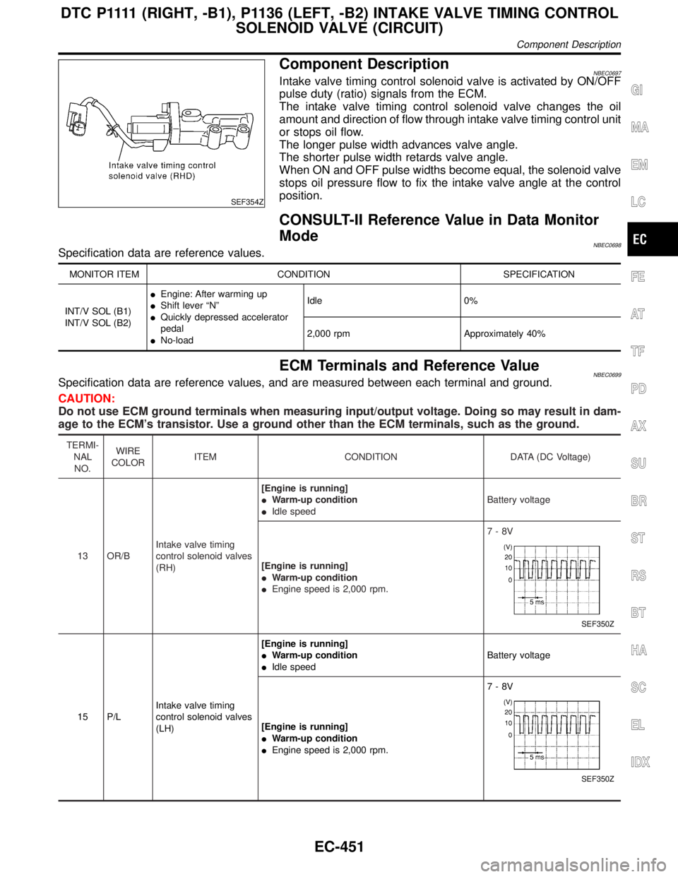
SEF354Z
Component DescriptionNBEC0697Intake valve timing control solenoid valve is activated by ON/OFF
pulse duty (ratio) signals from the ECM.
The intake valve timing control solenoid valve changes the oil
amount and direction of flow through intake valve timing control unit
or stops oil flow.
The longer pulse width advances valve angle.
The shorter pulse width retards valve angle.
When ON and OFF pulse widths become equal, the solenoid valve
stops oil pressure flow to fix the intake valve angle at the control
position.
CONSULT-II Reference Value in Data Monitor
Mode
NBEC0698Specification data are reference values.
MONITOR ITEM CONDITION SPECIFICATION
INT/V SOL (B1)
INT/V SOL (B2)IEngine: After warming up
IShift lever ªNº
IQuickly depressed accelerator
pedal
INo-loadIdle 0%
2,000 rpm Approximately 40%
ECM Terminals and Reference ValueNBEC0699Specification data are reference values, and are measured between each terminal and ground.
CAUTION:
Do not use ECM ground terminals when measuring input/output voltage. Doing so may result in dam-
age to the ECM's transistor. Use a ground other than the ECM terminals, such as the ground.
TERMI-
NAL
NO.WIRE
COLORITEM CONDITION DATA (DC Voltage)
13 OR/BIntake valve timing
control solenoid valves
(RH)[Engine is running]
IWarm-up condition
IIdle speedBattery voltage
[Engine is running]
IWarm-up condition
IEngine speed is 2,000 rpm.7-8V
SEF350Z
15 P/LIntake valve timing
control solenoid valves
(LH)[Engine is running]
IWarm-up condition
IIdle speedBattery voltage
[Engine is running]
IWarm-up condition
IEngine speed is 2,000 rpm.7-8V
SEF350Z
GI
MA
EM
LC
FE
AT
TF
PD
AX
SU
BR
ST
RS
BT
HA
SC
EL
IDX
D T C P 1111(RIGHT, -B1), P1136 (LEFT, -B2) INTAKE VALVE TIMING CONTROL
SOLENOID VALVE (CIRCUIT)
Component Description
EC-451
Page 988 of 2395

Wiring DiagramNBEC0703RIGHT BANKNBEC0703S01
MEC989C
GI
MA
EM
LC
FE
AT
TF
PD
AX
SU
BR
ST
RS
BT
HA
SC
EL
IDX
D T C P 1111(RIGHT, -B1), P1136 (LEFT, -B2) INTAKE VALVE TIMING CONTROL
SOLENOID VALVE (CIRCUIT)
Wiring Diagram
EC-453
Page 990 of 2395

Diagnostic ProcedureNBEC0704
1 CHECK OVERALL FUNCTION
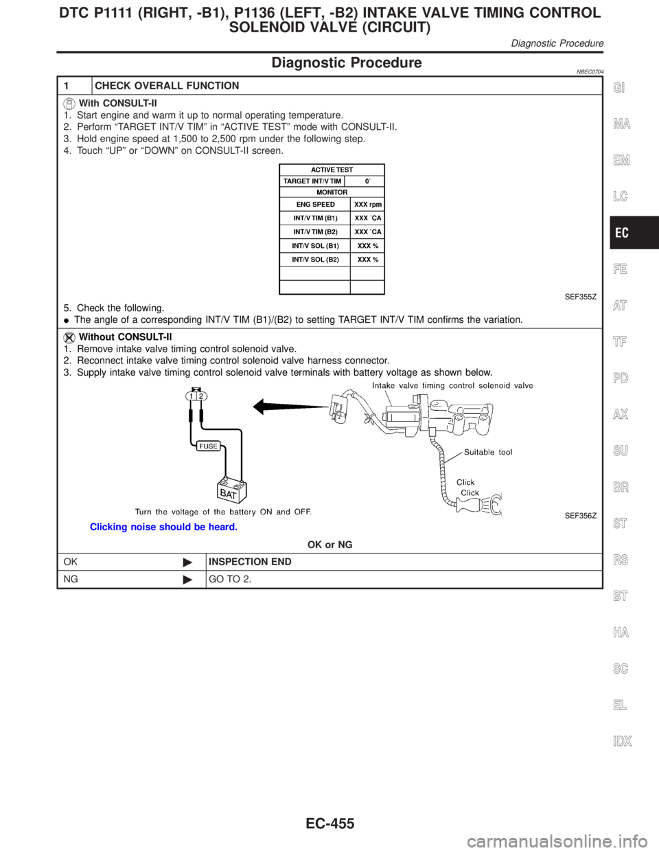
With CONSULT-II
1. Start engine and warm it up to normal operating temperature.
2. Perform ªTARGET INT/V TIMº in ªACTIVE TESTº mode with CONSULT-II.
3. Hold engine speed at 1,500 to 2,500 rpm under the following step.
4. Touch ªUPº or ªDOWNº on CONSULT-II screen.
SEF355Z
5. Check the following.
IThe angle of a corresponding INT/V TIM (B1)/(B2) to setting TARGET INT/V TIM confirms the variation.
Without CONSULT-II
1. Remove intake valve timing control solenoid valve.
2. Reconnect intake valve timing control solenoid valve harness connector.
3. Supply intake valve timing control solenoid valve terminals with battery voltage as shown below.
SEF356Z
Clicking noise should be heard.
OK or NG
OK©INSPECTION END
NG©GO TO 2.
GI
MA
EM
LC
FE
AT
TF
PD
AX
SU
BR
ST
RS
BT
HA
SC
EL
IDX
D T C P 1111(RIGHT, -B1), P1136 (LEFT, -B2) INTAKE VALVE TIMING CONTROL
SOLENOID VALVE (CIRCUIT)
Diagnostic Procedure
EC-455
Page 992 of 2395

5 CHECK INTAKE VALVE TIMING CONTROL SOLENOID VALVE
Check resistance between intake valve timing control solenoid valve terminals as follows.
SEF358Z
OK or NG
OK©GO TO 6.
NG©Repair intake valve timing control solenoid valve.
6 CHECK INTERMITTENT INCIDENT
Perform ªTROUBLE DIAGNOSIS FOR INTERMITTENT INCIDENTº, EC-140.
©INSPECTION END
GI
MA
EM
LC
FE
AT
TF
PD
AX
SU
BR
ST
RS
BT
HA
SC
EL
IDX
D T C P 1111(RIGHT, -B1), P1136 (LEFT, -B2) INTAKE VALVE TIMING CONTROL
SOLENOID VALVE (CIRCUIT)
Diagnostic Procedure (Cont'd)
EC-457
Page 994 of 2395

SEF002Z
COMPONENT DESCRIPTIONNBEC0523S02Swirl Control Valve Control Solenoid ValveNBEC0523S0201The swirl control valve control solenoid valve responds to signals
from the ECM. When the ECM sends an ON (ground) signal, the
solenoid valve is bypassed to apply intake manifold vacuum to the
swirl control valve actuator. This operation closes the swirl control
valve. When the ECM sends an OFF signal, the vacuum signal is
cut and the swirl control valve opens.
CONSULT-II Reference Value in Data Monitor
Mode
NBEC0524Specification data are reference values.
MONITOR ITEM CONDITION SPECIFICATION
SWRL CONT S/VIEngine speed: IdleEngine coolant temperature is
between 15ÉC (59ÉF) to 50ÉC
(122ÉF).ON
Engine coolant temperature is
above 55ÉC (131ÉF).OFF
ECM Terminals and Reference ValueNBEC0673Specification data are reference values and are measured between each terminal and ground.
CAUTION:
Do not use ECM ground terminals when measuring input/output voltage. Doing so may result in dam-
age to the ECM's transistor. Use a ground other than ECM terminals, such as the ground.
TERMI-
NAL
NO.WIRE
COLORITEM CONDITION DATA (DC Voltage)
29 GSwirl control valve con-
trol solenoid valve[Engine is running]
IIdle speed
IEngine coolant temperature is between 15 to
50ÉC (59 to 122ÉF).0 - 1.0V
[Engine is running]
IIdle speed
IEngine coolant temperature is above 55ÉC
(131ÉF).BATTERY VOLTAGE
(11 - 14V)
On Board Diagnosis LogicNBEC0526Malfunction is detected when
(Malfunction A)An improper voltage signal is sent to ECM through
swirl control valve control solenoid valve,
(Malfunction B)The vacuum signal is not sent to swirl control
valve under specified driving conditions, even though swirl control
valve control solenoid valve is ON,
(Malfunction C)The vacuum signal is sent to swirl control valve
even though swirl control valve control solenoid valve is OFF.
GI
MA
EM
LC
FE
AT
TF
PD
AX
SU
BR
ST
RS
BT
HA
SC
EL
IDX
DTC P1130 SWIRL CONTROL VALVE CONTROL SOLENOID VALVE
Description (Cont'd)
EC-459
Page 996 of 2395

SEF174Y
PROCEDURE FOR MALFUNCTION BNBEC0528S02TESTING CONDITION:
IFor best results, perform the test at a temperature above
5ÉC (41ÉF).
IBefore performing the following procedure, confirm that
battery voltage is more than 10V at idle, then stop engine
immediately.
With CONSULT-IINBEC0528S02011) Turn ignition switch ªOFFº and wait at least 10 seconds.
2) Turn ignition switch ªONº.
3) Check ªCOOLAN TEMP/Sº in ªDATA MONITORº mode with
CONSULT-II.
4) Confirm COOLAN TEMP/S value is 40ÉC (104ÉF) or less.
If the value is more than 40ÉC (104ÉF), park the vehicle in a
cool place and retry from step 1.
5) Start engine and wait until COOLAN TEMP/S value increases
to more than 55ÉC (131ÉF).
If 1st trip DTC is detected, go to ªDiagnostic Procedureº,
EC-463.
With GSTNBEC0528S0202Follow the procedure ªWith CONSULT-IIº above.
SEF174Y
PROCEDURE FOR MALFUNCTION CNBEC0528S03TESTING CONDITION:
IFor best results, perform the test at a temperature above
5ÉC (41ÉF).
IBefore performing the following procedure, confirm that
battery voltage is more than 10V at idle.
With CONSULT-IINBEC0528S03011) Start engine and warm it up to normal operating temperature.
2) Turn ignition switch ªOFFº and wait at least 10 seconds.
3) Turn ignition switch ªONº again and select ªDATA MONITORº
mode with CONSULT-II.
4) Start engine and let it idle for at least 20 seconds. If 1st trip
DTC is detected, go to ªDiagnostic Procedureº, EC-463.
With GSTNBEC0528S0302Follow the procedure ªWith CONSULT-IIº above.
GI
MA
EM
LC
FE
AT
TF
PD
AX
SU
BR
ST
RS
BT
HA
SC
EL
IDX
DTC P1130 SWIRL CONTROL VALVE CONTROL SOLENOID VALVE
DTC Confirmation Procedure (Cont'd)
EC-461
Page 998 of 2395

Diagnostic ProcedureNBEC0530PROCEDURE ANBEC0530S01
1 INSPECTION START
Do you have CONSULT-II?
YesorNo
Ye s©GO TO 2.
No©GO TO 3.
2 CHECK SWIRL CONTROL VALVE CONTROL SOLENOID VALVE CIRCUIT
With CONSULT-II
1. Turn ignition switch ªONº.
2. Select ªSWIRL CONT SOL VALVEº in ªACTIVE TESTº mode with CONSULT-II.
3. Touch ªONº and ªOFFº on CONSULT-II screen.
SEF003Z
4. Make sure that clicking sound is heard from the swirl control valve control solenoid valve.
OK or NG
OK©GO TO 6.
NG©GO TO 3.
GI
MA
EM
LC
FE
AT
TF
PD
AX
SU
BR
ST
RS
BT
HA
SC
EL
IDX
DTC P1130 SWIRL CONTROL VALVE CONTROL SOLENOID VALVE
Diagnostic Procedure
EC-463
Page 1000 of 2395

6 CHECK SWIRL CONTROL VALVE CONTROL SOLENOID VALVE
With CONSULT-II
1. Reconnect the disconnected harness connectors.
2. Start engine and let it idle.
3. Remove vacuum hose connected to swirl control valve actuator.
4. Select ªSWIRL CONT SOL VALVEº in ªACTIVE TESTº mode with CONSULT-II.
5. Touch ªONº and ªOFFº on CONSULT-II screen.
6. Check vacuum existence and operation delay time under the following conditions.
SEF004Z
Without CONSULT-II
1. Reconnect ECM harness connector.
2. Remove vacuum hose connected to swirl control valve actuator.
3. Start engine and let it idle.
4. Apply 12V of direct current between swirl control valve control solenoid valve terminals 1 and 2.
5. Check vacuum existence and operation delay time under the following conditions.
SEF005Z
OK or NG
OK©GO TO 7.
NG©Replace intake manifold collector assembly.
7 CHECK INTERMITTENT INCIDENT
Perform ªTROUBLE DIAGNOSIS FOR INTERMITTENT INCIDENTº, EC-140.
©INSPECTION END
GI
MA
EM
LC
FE
AT
TF
PD
AX
SU
BR
ST
RS
BT
HA
SC
EL
IDX
DTC P1130 SWIRL CONTROL VALVE CONTROL SOLENOID VALVE
Diagnostic Procedure (Cont'd)
EC-465
Page 1002 of 2395

3 CHECK SWIRL CONTROL VALVE CONTROL SOLENOID VALVE POWER SUPPLY CIRCUIT
1. Turn ignition switch ªOFFº.
2. Disconnect swirl control valve control solenoid valve harness connector.
SEF002Z
3. Turn ignition switch ªONº.
4. Check voltage between swirl control valve control solenoid valve terminal 1 and ground with CONSULT-II or tester.
SEF619X
OK or NG
OK©GO TO 5.
NG©GO TO 4.
4 DETECT MALFUNCTIONING PART
Check the following.
IHarness connectors M32, F23
I15A fuse
IHarness for open or short between swirl control valve control solenoid valve and fuse
©Repair harness or connectors.
5 CHECK SWIRL CONTROL VALVE CONTROL SOLENOID VALVE OUTPUT SIGNAL CIRCUIT FOR OPEN
AND SHORT
1. Turn ignition switch ªOFFº.
2. Disconnect ECM harness connector.
3. Check harness continuity between ECM terminal 29 and swirl control valve control solenoid valve terminal 2. Refer to
Wiring Diagram.
Continuity should exist.
4. Also check harness for short to ground and short to power.
OK or NG
OK©GO TO 6.
NG©Repair open circuit, short to ground or short to power in harness connectors.
GI
MA
EM
LC
FE
AT
TF
PD
AX
SU
BR
ST
RS
BT
HA
SC
EL
IDX
DTC P1130 SWIRL CONTROL VALVE CONTROL SOLENOID VALVE
Diagnostic Procedure (Cont'd)
EC-467
Page 1004 of 2395

7 CHECK SWIRL CONTROL VALVE CONTROL SOLENOID VALVE
With CONSULT-II
1. Reconnect the disconnected harness connectors.
2. Start engine and let it idle.
3. Remove vacuum hose connected to swirl control valve actuator.
4. Select ªSWIRL CONT SOL/Vº in ªACTIVE TESTº mode with CONSULT-II.
5. Touch ªONº and ªOFFº on CONSULT-II screen.
6. Check vacuum existence and operation delay time under the following conditions.
SEF004Z
Without CONSULT-II
1. Reconnect ECM harness connector.
2. Remove vacuum hose connected to swirl control valve actuator.
3. Start engine and let it idle.
4. Apply 12V of direct current between swirl control valve control solenoid valve terminals 1 and 2.
5. Check vacuum existence and operation delay time under the following conditions.
SEF005Z
OK or NG
OK©GO TO 8.
NG©Replace intake manifold collector assembly.
GI
MA
EM
LC
FE
AT
TF
PD
AX
SU
BR
ST
RS
BT
HA
SC
EL
IDX
DTC P1130 SWIRL CONTROL VALVE CONTROL SOLENOID VALVE
Diagnostic Procedure (Cont'd)
EC-469