ABS INFINITI QX56 2007 Factory Owners Manual
[x] Cancel search | Manufacturer: INFINITI, Model Year: 2007, Model line: QX56, Model: INFINITI QX56 2007Pages: 3061, PDF Size: 64.56 MB
Page 1513 of 3061

EC-430
< SERVICE INFORMATION >
DTC P0500 VSS
5. Maintain the following conditions for at least 60 consecutive sec-
onds.
6. If 1st trip DTC is detected, go to EC-430, "
Diagnosis Procedure".
Overall Function CheckINFOID:0000000003531934
Use this procedure to check the overall function of the vehicle speed sensor circuit. During this check, a 1st
trip DTC might not be confirmed.
WITH GST
1. Lift up drive wheels.
2. Start engine.
3. Read vehicle speed sensor signal in Service $01 with GST.
The vehicle speed sensor on GST should be able to exceed 10 km/h (6 MPH) when rotating wheels with
suitable gear position.
4. If NG, go to EC-430, "
Diagnosis Procedure".
Diagnosis ProcedureINFOID:0000000003531935
1.CHECK DTC WITH ABS ACTUATOR AND ELECTRIC UNIT (CONTROL UNIT)
Refer to BRC-11
.
OK or NG
OK >> GO TO 2.
NG >> Repair or replace.
2.CHECK COMBINATION METER FUNCTION
Refer to DI-5
.
>>INSPECTION END
ENG SPEED 1,600 - 6,000 rpm
COOLAN TEMP/S More than 70°C (158°F)
B/FUEL SCHDL 6.9 - 31.8 msec
Selector lever Except P or N position
PW/ST SIGNAL OFF
SEF196Y
Page 1550 of 3061

DTC P1211 TCS CONTROL UNIT
EC-467
< SERVICE INFORMATION >
C
D
E
F
G
H
I
J
K
L
MA
EC
N
P O
DTC P1211 TCS CONTROL UNIT
DescriptionINFOID:0000000003531981
The malfunction information related to TCS is transferred through the CAN communication line from “ABS
actuator and electric unit (control unit)” to ECM.
Be sure to erase the malfunction information such as DTC not only for “ABS actuator and electric unit
(control unit)” but also for ECM after TCS related repair.
On Board Diagnosis LogicINFOID:0000000003531982
Freeze frame data is not stored in the ECM for this self-diagnosis.
The MIL will not light up for this self-diagnosis.
DTC Confirmation ProcedureINFOID:0000000003531983
TESTING CONDITION:
Before performing the following procedure, confirm that battery voltage is more than 10.5V at idle.
WITH CONSULT-II
1. Turn ignition switch ON.
2. Select “DATA MONITOR” mode with CONSULT-II.
3. Start engine and let it idle for at least 60 seconds.
4. If 1st trip DTC is detected, go to EC-467, "
Diagnosis Procedure"
.
WITH GST
Follow the procedure “WITH CONSULT-II” above.
Diagnosis ProcedureINFOID:0000000003531984
Go to BRC-11.
DTC No. Trouble diagnosis name DTC detecting condition Possible cause
P1211
1211TCS control unitECM receives a malfunction information from
“ABS actuator electric unit (control unit)”• ABS actuator and electric unit (control
unit)
• TCS related parts
SEF058Y
Page 1551 of 3061

EC-468
< SERVICE INFORMATION >
DTC P1212 TCS COMMUNICATION LINE
DTC P1212 TCS COMMUNICATION LINE
DescriptionINFOID:0000000003531985
NOTE:
•If DTC P1212 is displayed with DTC U1000 or U1001, first perform the trouble diagnosis for DTC
U1000, U1001. Refer to EC-145
.
•If DTC P1212 is displayed with DTC U1010, first perform the trouble diagnosis for DTC U1010. Refer
to EC-147
.
This CAN communication line is used to control the smooth engine operation during the TCS operation. Pulse
signals are exchanged between ECM and “ABS actuator and electric unit (control unit)”.
Be sure to erase the malfunction information such as DTC not only for “ABS actuator and electric unit
(control unit)” but also for ECM after TCS related repair.
On Board Diagnosis LogicINFOID:0000000003531986
Freeze frame data is not stored in the ECM for this self-diagnosis.
The MIL will not light up for this self-diagnosis.
DTC Confirmation ProcedureINFOID:0000000003531987
TESTING CONDITION:
Before performing the following procedure, confirm that battery voltage is more than 10.5V at idle.
WITH CONSULT-II
1. Turn ignition switch ON.
2. Select “DATA MONITOR” mode with CONSULT-II.
3. Start engine and let it idle for at least 10 seconds.
4. If 1st trip DTC is detected, go to EC-468, "
Diagnosis Procedure"
.
WITH GST
Follow the procedure “WITH CONSULT-II” above.
Diagnosis ProcedureINFOID:0000000003531988
Go to BRC-11.
DTC No. Trouble diagnosis name DTC detecting condition Possible cause
P1212
1212TCS communication lineECM can not receive the information from
“ABS actuator and electric unit (control
unit)” continuously.• Harness or connectors
(The CAN communication line is open or short-
ed.)
• ABS actuator and electric unit (control unit)
• Dead (Weak) battery
SEF058Y
Page 1618 of 3061

DTC P1574 ICC VEHICLE SPEED SENSOR
EC-535
< SERVICE INFORMATION >
C
D
E
F
G
H
I
J
K
L
MA
EC
N
P O
DTC P1574 ICC VEHICLE SPEED SENSOR
Component DescriptionINFOID:0000000003532070
The ECM receives two vehicle speed signals via CAN communication line. One is sent from “unified meter and
A/C amp.”, and the other is from TCM (Transmission control module). The ECM uses these signals for ICC
control. Refer to ACS-6
for ICC functions.
On Board Diagnosis LogicINFOID:0000000003532071
•This self-diagnosis has the one trip detection logic.
•The MIL will not light up for this self-diagnosis.
NOTE:
•If DTC P1574 is displayed with DTC U1000, U1001, first perform the trouble diagnosis for DTC U1000,
U1001. Refer to EC-145
.
•If DTC P1574 is displayed with DTC U1010, first perform the trouble diagnosis for DTC U1010. Refer
to EC-147
.
•If DTC P1574 is displayed with DTC P0500, first perform the trouble diagnosis for DTC P0500. Refer
to EC-429
.
•If DTC P1574 is displayed with DTC P0605, first perform the trouble diagnosis for DTC P0605. Refer
to EC-444
.
DTC Confirmation ProcedureINFOID:0000000003532072
CAUTION:
Always drive vehicle at a safe speed.
NOTE:
If DTC Confirmation Procedure has been previously conducted, always turn ignition switch OFF and wait at
least 10 seconds before conducting the next test.
TESTING CONDITION:
Step 3 may be conducted with the drive wheels lifted in the shop or by driving the vehicle. If a road test
is expected to be easier, it is unnecessary to lift the vehicle.
WITH CONSULT-II
1. Start engine.
2. Select “DATA MONITOR” mode with CONSULT-II.
3. Drive the vehicle at more than 40 km/h (25MPH).
4. If DTC is detected, go to EC-536, "
Diagnosis Procedure".
WITH GST
Follow the procedure “WITH CONSULT-II” above.
DTC No. Trouble Diagnosis Name DTC Detecting Condition Possible Cause
P1574
1574ICC vehicle speed sensorECM detects a difference between two vehicle
speed signals is out of the specified range.• Harness or connectors
(The CAN communication line is open or
shorted.)
• Combination meter
• ABS actuator and electric unit (control unit)
• Wheel sensor
•TCM
•ECM
SEF058Y
Page 1619 of 3061

EC-536
< SERVICE INFORMATION >
DTC P1574 ICC VEHICLE SPEED SENSOR
Diagnosis Procedure
INFOID:0000000003532073
1.CHECK DTC WITH TCM
Check DTC with TCM. Refer to AT-39, "
OBD-II Diagnostic Trouble Code (DTC)".
OK or NG
OK >> GO TO 2.
NG >> Perform trouble shooting relevant to DTC indicated.
2.CHECK DTC WITH “ABS ACTUATOR AND ELECTRIC UNIT (CONTROL UNIT)”
Refer to BRC-11
.
OK or NG
OK >> GO TO 3.
NG >> Repair or replace.
3.CHECK COMBINATION METER FUNCTION
Refer to DI-5
.
>>INSPECTION END
Page 1620 of 3061

DTC P1574 ASCD VEHICLE SPEED SENSOR
EC-537
< SERVICE INFORMATION >
C
D
E
F
G
H
I
J
K
L
MA
EC
N
P O
DTC P1574 ASCD VEHICLE SPEED SENSOR
Component DescriptionINFOID:0000000003532074
The ECM receives two vehicle speed sensor signals via CAN communication line. One is sent from combina-
tion meter and the other is from TCM (Transmission control module). The ECM uses these signals for ASCD
control. Refer to EC-30
for ASCD functions.
On Board Diagnosis LogicINFOID:0000000003532075
•This self-diagnosis has the one trip detection logic.
•The MIL will not light up for this self-diagnosis.
NOTE:
•If DTC P1574 is displayed with DTC U1000, U1001, first perform the trouble diagnosis for DTC U1000,
U1001. Refer to EC-145
.
•If DTC P1574 is displayed with DTC U1010, first perform the trouble diagnosis for DTC U1010. Refer
to EC-147
.
•If DTC P1574 is displayed with DTC P0500, first perform the trouble diagnosis for DTC P0500. Refer
to EC-429
.
•If DTC P1574 is displayed with DTC P0605, first perform the trouble diagnosis for DTC P0605. Refer
to EC-444
.
DTC Confirmation ProcedureINFOID:0000000003532076
CAUTION:
Always drive vehicle at a safe speed.
NOTE:
If DTC Confirmation Procedure has been previously conducted, always turn ignition switch OFF and wait at
least 10 seconds before conducting the next test.
TESTING CONDITION:
Step 3 may be conducted with the drive wheels lifted in the shop or by driving the vehicle. If a road test
is expected to be easier, it is unnecessary to lift the vehicle.
WITH CONSULT-II
1. Start engine (VDC switch OFF).
2. Select “DATA MONITOR” mode with CONSULT-II.
3. Drive the vehicle at more than 40 km/h (25 MPH).
4. If DTC is detected, go to EC-538, "
Diagnosis Procedure" .
WITH GST
Follow the procedure “WITH CONSULT-II” above.
DTC No.Trouble Diagnosis
NameDTC Detecting Condition Possible Cause
P1574
1574ASCD vehicle speed
sensorECM detects a difference between two vehicle
speed signals is out of the specified range.• Harness or connectors
(The CAN communication line is open or
shorted.)
• Combination meter
• ABS actuator and electric unit (control unit)
• Wheel sensor
•TCM
•ECM
SEF058Y
Page 1621 of 3061

EC-538
< SERVICE INFORMATION >
DTC P1574 ASCD VEHICLE SPEED SENSOR
Diagnosis Procedure
INFOID:0000000003532077
1.CHECK DTC WITH TCM
Check DTC with TCM. Refer to AT-39, "
OBD-II Diagnostic Trouble Code (DTC)".
OK or NG
OK >> GO TO 2.
NG >> Perform trouble shooting relevant to DTC indicated.
2.CHECK DTC WITH ABS ACTUATOR AND ELECTRIC UNIT (CONTROL UNIT)
Refer to BRC-11
.
OK or NG
OK >> GO TO 3.
NG >> Repair or replace.
3.CHECK COMBINATION METER FUNCTION
Check combination meter function.
Refer to DI-5
.
>>INSPECTION END
Page 1741 of 3061

EI-12
< SERVICE INFORMATION >
FRONT BUMPER
FRONT BUMPER
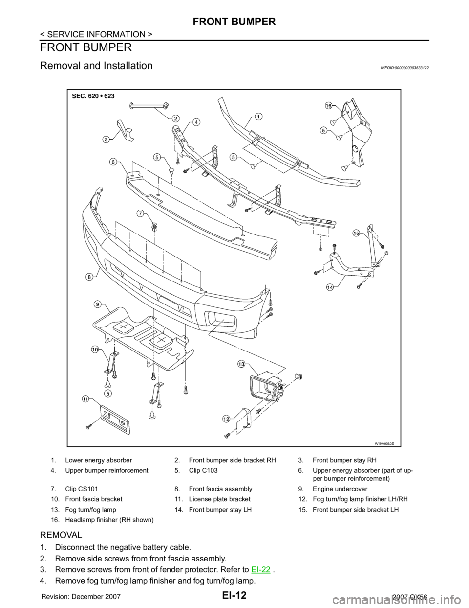
Removal and InstallationINFOID:0000000003533122
REMOVAL
1. Disconnect the negative battery cable.
2. Remove side screws from front fascia assembly.
3. Remove screws from front of fender protector. Refer to EI-22
.
4. Remove fog turn/fog lamp finisher and fog turn/fog lamp.
1. Lower energy absorber 2. Front bumper side bracket RH 3. Front bumper stay RH
4. Upper bumper reinforcement 5. Clip C103 6. Upper energy absorber (part of up-
per bumper reinforcement)
7. Clip CS101 8. Front fascia assembly 9. Engine undercover
10. Front fascia bracket 11. License plate bracket 12. Fog turn/fog lamp finisher LH/RH
13. Fog turn/fog lamp 14. Front bumper stay LH 15. Front bumper side bracket LH
16. Headlamp finisher (RH shown)
WIIA0952E
Page 1742 of 3061

FRONT BUMPER
EI-13
< SERVICE INFORMATION >
C
D
E
F
G
H
J
K
L
MA
B
EI
N
O
P
• Disconnect harnesses.
5. Remove engine undercover.
6. Remove fasteners, release clips and remove front fascia assembly.
7. Remove plastic clips and remove upper energy absorber.
8. Remove upper bumper reinforcement.
9. Remove plastic clips and remove lower energy absorber.
10. Remove front bumper stays and front bumper side brackets, LH and RH.
INSTALLATION
Installation is in the reverse order of removal.
Page 1743 of 3061

EI-14
< SERVICE INFORMATION >
REAR BUMPER
REAR BUMPER
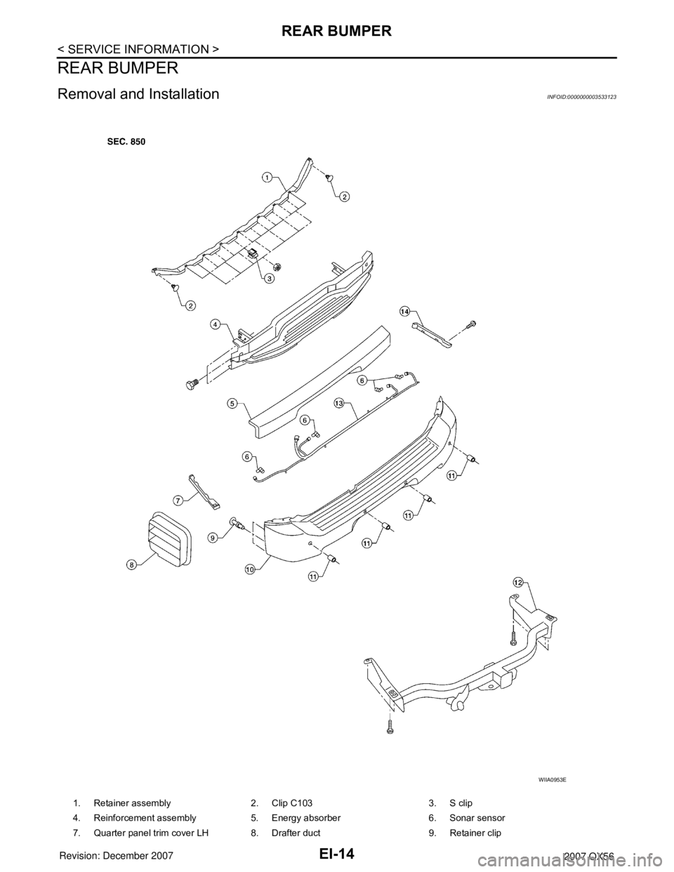
Removal and InstallationINFOID:0000000003533123
1. Retainer assembly 2. Clip C103 3. S clip
4. Reinforcement assembly 5. Energy absorber 6. Sonar sensor
7. Quarter panel trim cover LH 8. Drafter duct 9. Retainer clip
WIIA0953E