INFINITI QX56 2007 Factory User Guide
QX56 2007
INFINITI
INFINITI
https://www.carmanualsonline.info/img/42/57029/w960_57029-0.png
INFINITI QX56 2007 Factory User Guide
Page 105 of 3061

A/T CONTROL SYSTEM
AT-35
< SERVICE INFORMATION >
D
E
F
G
H
I
J
K
L
MA
B
AT
N
O
P
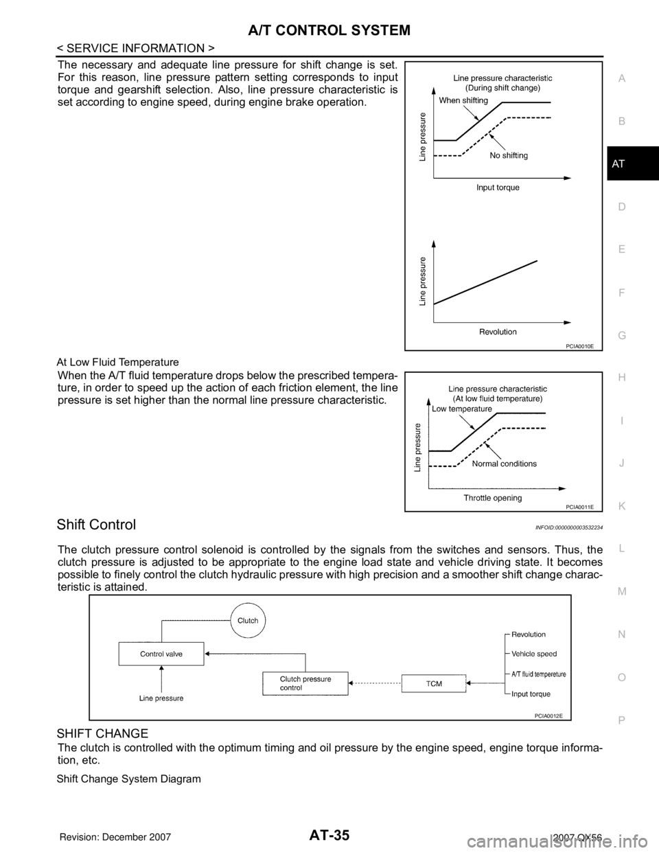
The necessary and adequate line pressure for shift change is set.
For this reason, line pressure pattern setting corresponds to input
torque and gearshift selection. Also, line pressure characteristic is
set according to engine speed, during engine brake operation.
At Low Fluid Temperature
When the A/T fluid temperature drops below the prescribed tempera-
ture, in order to speed up the action of each friction element, the line
pressure is set higher than the normal line pressure characteristic.
Shift ControlINFOID:0000000003532234
The clutch pressure control solenoid is controlled by the signals from the switches and sensors. Thus, the
clutch pressure is adjusted to be appropriate to the engine load state and vehicle driving state. It becomes
possible to finely control the clutch hydraulic pressure with high precision and a smoother shift change charac-
teristic is attained.
SHIFT CHANGE
The clutch is controlled with the optimum timing and oil pressure by the engine speed, engine torque informa-
tion, etc.
Shift Change System Diagram
PCIA0010E
PCIA0011E
PCIA0012E
Page 106 of 3061

AT-36
< SERVICE INFORMATION >
A/T CONTROL SYSTEM
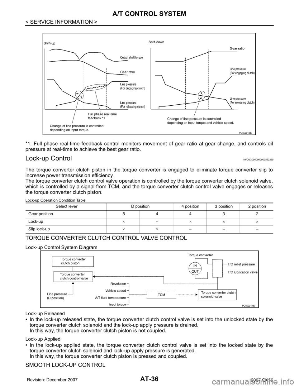
*1: Full phase real-time feedback control monitors movement of gear ratio at gear change, and controls oil
pressure at real-time to achieve the best gear ratio.
Lock-up ControlINFOID:0000000003532235
The torque converter clutch piston in the torque converter is engaged to eliminate torque converter slip to
increase power transmission efficiency.
The torque converter clutch control valve operation is controlled by the torque converter clutch solenoid valve,
which is controlled by a signal from TCM, and the torque converter clutch control valve engages or releases
the torque converter clutch piston.
Lock-up Operation Condition Table
TORQUE CONVERTER CLUTCH CONTROL VALVE CONTROL
Lock-up Control System Diagram
Lock-up Released
• In the lock-up released state, the torque converter clutch control valve is set into the unlocked state by the
torque converter clutch solenoid and the lock-up apply pressure is drained.
In this way, the torque converter clutch piston is not coupled.
Lock-up Applied
• In the lock-up applied state, the torque converter clutch control valve is set into the locked state by the
torque converter clutch solenoid and lock-up apply pressure is generated.
In this way, the torque converter clutch piston is pressed and coupled.
SMOOTH LOCK-UP CONTROL
PCIA0013E
Select lever D position 4 position 3 position 2 position
Gear position 5 4 4 3 2
Lock-up×–×××
Slip lock-up××–––
PCIA0014E
Page 121 of 3061
TROUBLE DIAGNOSIS
AT-51
< SERVICE INFORMATION >
D
E
F
G
H
I
J
K
L
MA
B
AT
N
O
P
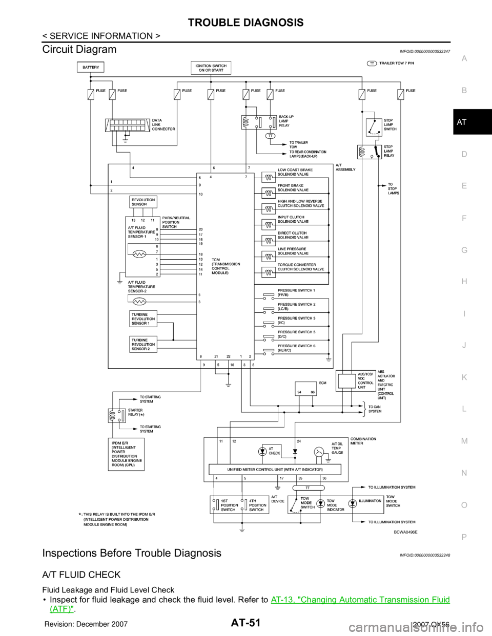
Circuit DiagramINFOID:0000000003532247
Inspections Before Trouble DiagnosisINFOID:0000000003532248
A/T FLUID CHECK
Fluid Leakage and Fluid Level Check
• Inspect for fluid leakage and check the fluid level. Refer to AT-13, "Changing Automatic Transmission Fluid
(ATF)".
BCWA0496E
Page 162 of 3061
AT-92
< SERVICE INFORMATION >
DTC U1000 CAN COMMUNICATION LINE
Wiring Diagram - AT - CAN
INFOID:0000000003532264
TCM Input/Output Signal Reference Values
Refer to AT-82, "TCM Input/Output Signal Reference Value".
BCWA0320E
Page 165 of 3061
DTC P0615 START SIGNAL CIRCUIT
AT-95
< SERVICE INFORMATION >
D
E
F
G
H
I
J
K
L
MA
B
AT
N
O
P
Wiring Diagram - AT - STSIGINFOID:0000000003532271
TCM Input/Output Signal Reference Values
Refer to AT-82, "TCM Input/Output Signal Reference Value".
Diagnosis ProcedureINFOID:0000000003532272
1.CHECK STARTER RELAY
BCWA0321E
Page 170 of 3061
AT-100
< SERVICE INFORMATION >
DTC P0705 PARK/NEUTRAL POSITION SWITCH
Wiring Diagram - AT - PNP/SW
INFOID:0000000003532283
Diagnosis ProcedureINFOID:0000000003532284
1.CHECK PNP SW CIRCUIT
With CONSULT-II
BCWA0520E
Page 176 of 3061
AT-106
< SERVICE INFORMATION >
DTC P0720 VEHICLE SPEED SENSOR A/T (REVOLUTION SENSOR)
If the check result is NG, go to AT-107, "Diagnosis Procedure".
WITH GST
Follow the procedure “With CONSULT-II”.
Wiring Diagram - AT - VSSA/TINFOID:0000000003532296
BCWA0497E
Page 190 of 3061
AT-120
< SERVICE INFORMATION >
DTC P1710 A/T FLUID TEMPERATURE SENSOR CIRCUIT
Wiring Diagram - AT - FTS
INFOID:0000000003532333
Diagnosis ProcedureINFOID:0000000003532334
1.CHECK A/T FLUID TEMPERATURE SENSOR 1 SIGNAL
With CONSULT-II
BCWA0323E
Page 228 of 3061
AT-158
< SERVICE INFORMATION >
MAIN POWER SUPPLY AND GROUND CIRCUIT
MAIN POWER SUPPLY AND GROUND CIRCUIT
Wiring Diagram - AT - MAININFOID:0000000003532438
TCM Input/Output Signal Reference Values
Refer to AT-82, "TCM Input/Output Signal Reference Value".
BCWA0324E
Page 233 of 3061
TOW MODE SWITCH
AT-163
< SERVICE INFORMATION >
D
E
F
G
H
I
J
K
L
MA
B
AT
N
O
P
TOW MODE SWITCH
DescriptionINFOID:0000000003532444
When tow mode switch is “ON”, tow mode switch signals are sent to TCM from combination meter by CAN
communication line.Then it`s a tow mode condition.
Wiring Diagram - AT - TMSWINFOID:0000000003532445
BCWA0498E


