ground INFINITI QX56 2011 Factory Owners Manual
[x] Cancel search | Manufacturer: INFINITI, Model Year: 2011, Model line: QX56, Model: INFINITI QX56 2011Pages: 5598, PDF Size: 94.53 MB
Page 219 of 5598

AV
AROUND VIEW MONITOR CONTROL UNITAV-71
< ECU DIAGNOSIS INFORMATION >
C
DE
F
G H
I
J
K L
M B A
O P
AROUND VIEW MONITOR CONTROL UNIT
Reference ValueINFOID:0000000006216232
TERMINAL LAYOUT
PHYSICAL VALUES
JSNIA0833ZZ
Te r m i n a l
(Wire color) Description
ConditionReference value
(Approx.)
+ – Signal name Input/
Output
1
(B) Ground Ground — Ignition
switch
ON —0 V
2
(Y/G) Ground Battery power supply Input Ignition
switch OFF — Battery voltage
3
(GR/L) Ground Ignition signal Input Ignition
switch
ON — Battery voltage
4
(V) Ground ACC power supply Input Ignition
switch ACC — Battery voltage
5
(L/W) Ground Illumination signal Input Ignition
switch OFF Lighting switch is OFF. 0 V
Lighting switch is ON. 12.0 V
6
(BR/ W) Ground
Vehicle speed signal
(8-pulse) InputIgnition
switch ON When vehicle speed is ap-
prox. 40 km/h (25 MPH) NOTE:
The maximum voltage varies de-
pending on the specification
(destination unit).
7
(P) Ground Reverse signal Input Ignition
switch ON R position 12.0 V
Other than R position 0 V
9
(B/O) Ground Control signal — Ignition
switch ON —0 V
13
(B/O) Ground Control signal — Ignition
switch
ON —0 V
JSNIA0012GB
Revision: 2010 May2011 QX56
Page 220 of 5598
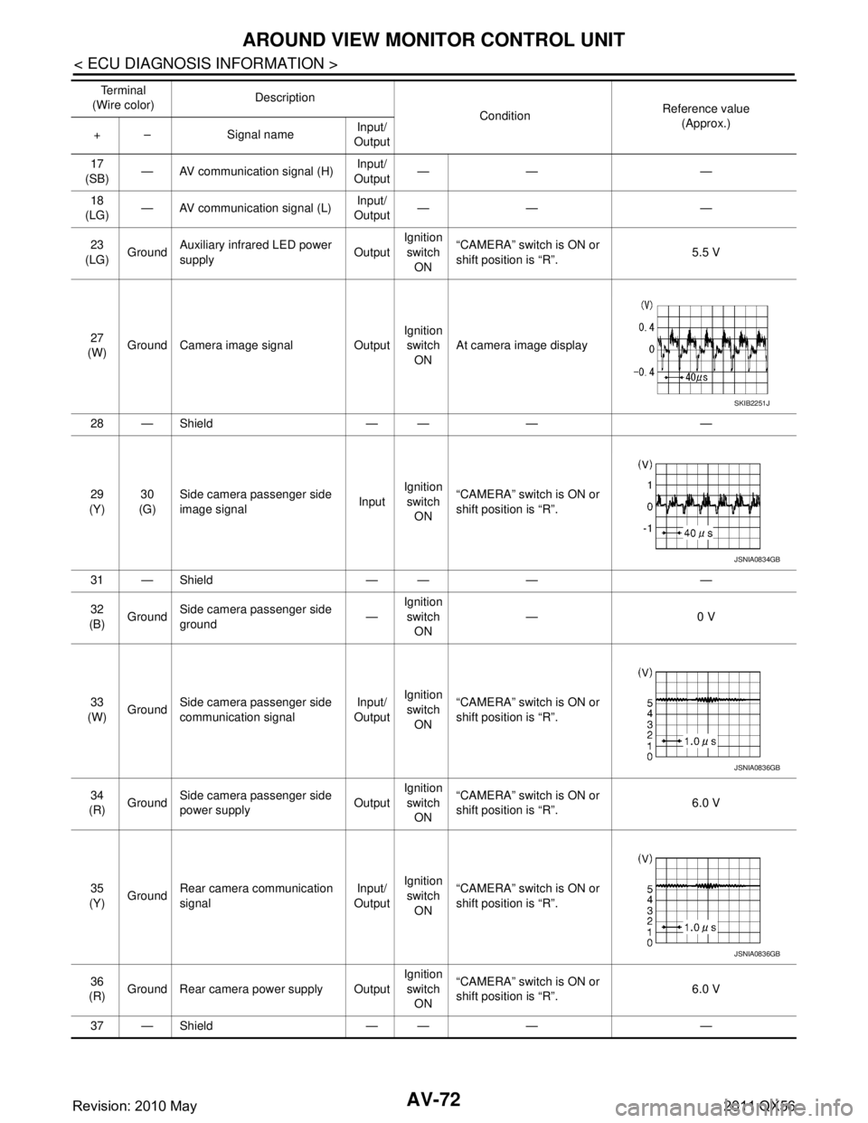
AV-72
< ECU DIAGNOSIS INFORMATION >
AROUND VIEW MONITOR CONTROL UNIT
17
(SB) — AV communication signal (H)
Input/
Output —— —
18
(LG) — AV communication signal (L) Input/
Output —— —
23
(LG) Ground Auxiliary infrared LED power
supply OutputIgnition
switch ON “CAMERA” switch is ON or
shift position is “R”.
5.5 V
27
(W) Ground Camera image signal Output Ignition
switch ON At camera image display
28 — Shield — — — —
29
(Y) 30
(G) Side camera passenger side
image signal
InputIgnition
switch
ON “CAMERA” switch is ON or
shift position is “R”.
31 — Shield — — — —
32
(B) Ground
Side camera passenger side
ground —Ignition
switch
ON —0 V
33
(W) Ground Side camera passenger side
communication signal Input/
Output Ignition
switch ON “CAMERA” switch is ON or
shift position is “R”.
34
(R) Ground Side camera passenger side
power supply OutputIgnition
switch ON “CAMERA” switch is ON or
shift position is “R”.
6.0 V
35
(Y) Ground Rear camera communication
signal Input/
Output Ignition
switch ON “CAMERA” switch is ON or
shift position is “R”.
36
(R) Ground Rear camera power supply Output Ignition
switch ON “CAMERA” switch is ON or
shift position is “R”.
6.0 V
37 — Shield — — — —
Te r m i n a l
(Wire color) Description
ConditionReference value
(Approx.)
+ – Signal name Input/
Output
SKIB2251J
JSNIA0834GB
JSNIA0836GB
JSNIA0836GB
Revision: 2010 May2011 QX56
Page 221 of 5598
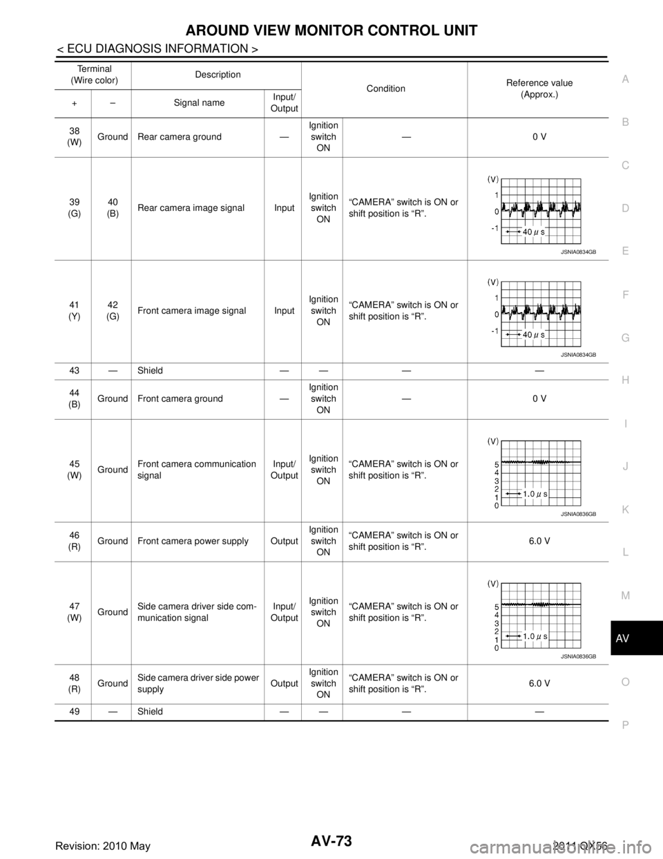
AV
AROUND VIEW MONITOR CONTROL UNITAV-73
< ECU DIAGNOSIS INFORMATION >
C
DE
F
G H
I
J
K L
M B A
O P
38
(W) Ground Rear camera ground — Ignition
switch ON —0 V
39
(G) 40
(B) Rear camera image signal Input Ignition
switch
ON “CAMERA” switch is ON or
shift position is “R”.
41
(Y) 42
(G) Front camera image signal Input Ignition
switch ON “CAMERA” switch is ON or
shift position is “R”.
43 — Shield — — — —
44
(B) Ground Front camera ground — Ignition
switch ON —0 V
45
(W) Ground Front camera communication
signal Input/
Output Ignition
switch ON “CAMERA” switch is ON or
shift position is “R”.
46
(R) Ground Front camera power supply Output Ignition
switch ON “CAMERA” switch is ON or
shift position is “R”.
6.0 V
47
(W) Ground Side camera driver side com-
munication signal Input/
Output Ignition
switch ON “CAMERA” switch is ON or
shift position is “R”.
48
(R) Ground
Side camera driver side power
supply OutputIgnition
switch
ON “CAMERA” switch is ON or
shift position is “R”.
6.0 V
49 — Shield — — — — Te r m i n a l
(Wire color) Description
ConditionReference value
(Approx.)
+ – Signal name Input/
Output
JSNIA0834GB
JSNIA0834GB
JSNIA0836GB
JSNIA0836GB
Revision: 2010 May2011 QX56
Page 222 of 5598
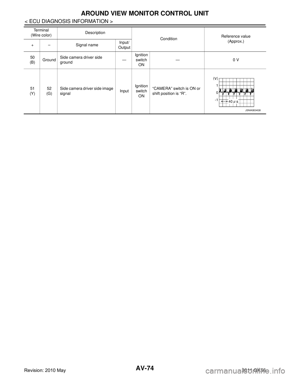
AV-74
< ECU DIAGNOSIS INFORMATION >
AROUND VIEW MONITOR CONTROL UNIT
50
(B) Ground Side camera driver side
ground
—Ignition
switch ON —0 V
51
(Y) 52
(G) Side camera driver side image
signal
InputIgnition
switch
ON “CAMERA” switch is ON or
shift position is “R”.
Te r m i n a l
(Wire color) Description
ConditionReference value
(Approx.)
+ – Signal name Input/
Output
JSNIA0834GB
Revision: 2010 May2011 QX56
Page 224 of 5598
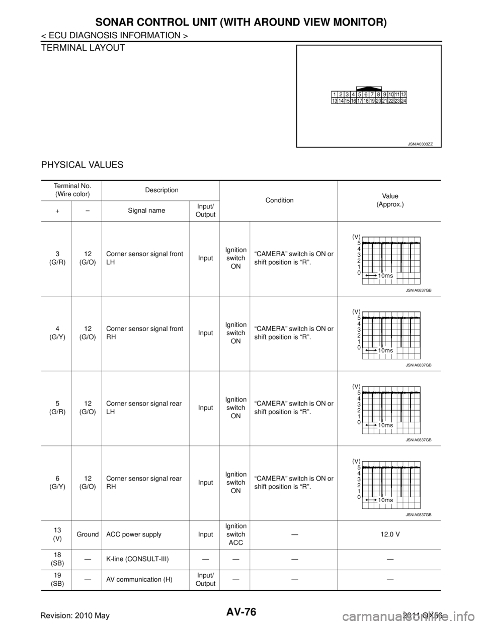
AV-76
< ECU DIAGNOSIS INFORMATION >
SONAR CONTROL UNIT (WITH AROUND VIEW MONITOR)
TERMINAL LAYOUT
PHYSICAL VALUES
JSNIA0303ZZ
Te r m i n a l N o .(Wire color) Description
ConditionVa l u e
(Approx.)
+ – Signal name Input/
Output
3
(G/R) 12
(G/O) Corner sensor signal front
LH
InputIgnition
switch ON “CAMERA” switch is ON or
shift position is “R”.
4
(G/Y) 12
(G/O) Corner sensor signal front
RH
InputIgnition
switch
ON “CAMERA” switch is ON or
shift position is “R”.
5
(G/R) 12
(G/O) Corner sensor signal rear
LH
InputIgnition
switch ON “CAMERA” switch is ON or
shift position is “R”.
6
(G/Y) 12
(G/O) Corner sensor signal rear
RH
InputIgnition
switch ON “CAMERA” switch is ON or
shift position is “R”.
13
(V) Ground ACC power supply Input Ignition
switch ACC — 12.0 V
18
(SB) — K-line (CONSULT-III) — — — —
19
(SB) — AV communication (H) Input/
Output —— —
JSNIA0837GB
JSNIA0837GB
JSNIA0837GB
JSNIA0837GB
Revision: 2010 May2011 QX56
Page 225 of 5598

AV
SONAR CONTROL UNIT (WITH AROUND VIEW MONITOR)
AV-77
< ECU DIAGNOSIS INFORMATION >
C
D E
F
G H
I
J
K L
M B A
O P
Fail-SafeINFOID:0000000006216234
Sonar control unit has diagnosis function which can detect corner sensor malfunction and sensor harness
disconnection.
It transmits the malfunction status to around view moni tor control unit and informs the malfunction to the user
by displaying continuously red sonar indicator.
DTC IndexINFOID:0000000006216235
NOTE:
“TIME” means the following.
0: Means detected malfunction at present. (From ma lfunction detection to turning ignition switch OFF)
1–39: Means detected malfunction in past.
20
(LG) — AV communication (L)
Input/
Output —— —
24
(B) Ground Ground — Ignition
switch
ON —0 V
Te r m i n a l N o .
(Wire color) Description
ConditionVa l u e
(Approx.)
+ – Signal name Input/
Output
DTC Display item Malfunction is detected when... Reference
B2700 CORNER SENSOR [FL]
[B2700]
Corner sensor front LH is malfunctioning.
AV- 1 5 3 , "
DTC Logic"
B2701SENSOR HARNESS OPEN [CR-FL]
[B2701] Corner sensor front LH harness circuit is open.
AV- 1 5 4 , "Diagnosis Procedure"
B2702CORNER SENSOR [FR]
[B2702] Corner sensor front RH is malfunctioning.
AV- 1 5 5 , "DTC Logic"
B2703SENSOR HARNESS OPEN [CR-
FR]
[B2703] Corner sensor front RH harness circuit is open.
AV- 1 5 6 , "Diagnosis Procedure"
B2704CORNER SENSOR [RL]
[B2704] Corner sensor rear LH is malfunctioning.
AV- 1 5 7 , "DTC Logic"
B2705SENSOR HARNESS OPEN [CR-RL]
[B2705]
Corner sensor rear LH harness circuit is open.
AV- 1 5 8 , "Diagnosis Procedure"
B2706CORNER SENSOR [RR]
[B2706] Corner sensor rear RH is malfunctioning.
AV- 1 5 9 , "DTC Logic"
B2707SENSOR HARNESS OPEN [CR-
RR]
[B2707] Corner sensor rear RH harness circuit is open.
AV- 1 6 0 , "Diagnosis Procedure"
Revision: 2010 May2011 QX56
Page 261 of 5598
AV
CALIBRATING CAMERA IMAGE (AROUND VIEW MONITOR)
AV-113
< BASIC INSPECTION >
C
D E
F
G H
I
J
K L
M B A
O P
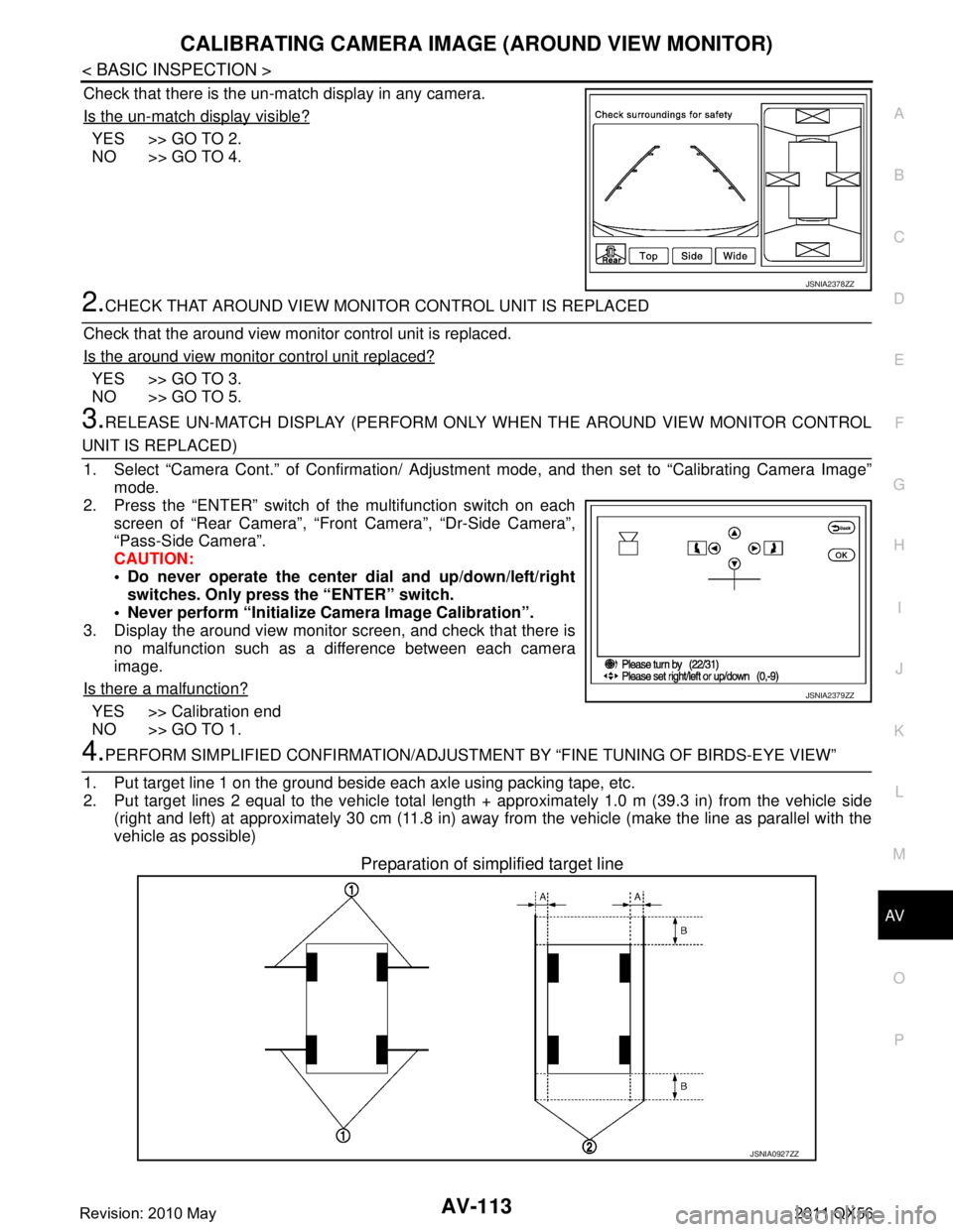
Check that there is the un-match display in any camera.
Is the un-match display visible?
YES >> GO TO 2.
NO >> GO TO 4.
2.CHECK THAT AROUND VIEW MONITOR CONTROL UNIT IS REPLACED
Check that the around view monitor control unit is replaced.
Is the around view monitor control unit replaced?
YES >> GO TO 3.
NO >> GO TO 5.
3.RELEASE UN-MATCH DISPLAY (PERFORM ONLY WHEN THE AROUND VIEW MONITOR CONTROL
UNIT IS REPLACED)
1. Select “Camera Cont.” of Confirmation/ Adjust ment mode, and then set to “Calibrating Camera Image”
mode.
2. Press the “ENTER” switch of the multifunction switch on each screen of “Rear Camera”, “Front Camera”, “Dr-Side Camera”\
,
“Pass-Side Camera”.
CAUTION:
Do never operate the center dial and up/down/left/right
switches. Only press the “ENTER” switch.
Never perform “Initialize Camera Image Calibration”.
3. Display the around view monitor screen, and check that there is
no malfunction such as a difference between each camera
image.
Is there a malfunction?
YES >> Calibration end
NO >> GO TO 1.
4.PERFORM SIMPLIFIED CONFIRMATION/ADJUSTM ENT BY “FINE TUNING OF BIRDS-EYE VIEW”
1. Put target line 1 on the ground beside each axle using packing tape, etc.
2. Put target lines 2 equal to the vehicle total length + approximately 1.0 m (39.3 in) from the vehicle side
(right and left) at approximately 30 cm (11.8 in) away from the vehicle (make the line as parallel with the
vehicle as possible)
Preparation of simplified target line
JSNIA2378ZZ
JSNIA2379ZZ
JSNIA0927ZZ
Revision: 2010 May2011 QX56
Page 262 of 5598
AV-114
< BASIC INSPECTION >
CALIBRATING CAMERA IMAGE (AROUND VIEW MONITOR)
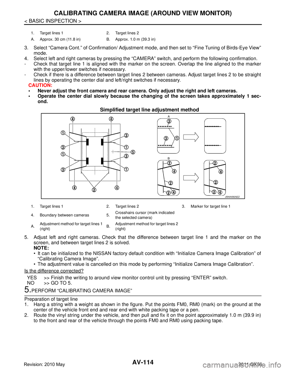
3. Select “Camera Cont.” of Confirmation/ Adjustment mode, and then set to “Fine Tuning of Birds-Eye View”
mode.
4. Select left and right cameras by pressing the “CAM ERA” switch, and perform the following confirmation.
- Check that target line 1 is aligned with the marker on the screen. Overlap the line aligned to the marker
with the upper/lower switches if necessary.
- Check if there is a difference between target lines 2 between cameras. Adjust target lines 2 to be straight
lines by operating the center dial and left/right switches if necessary.
CAUTION:
Never adjust the front camera and rear camer a. Only adjust the right and left cameras.
Operate the center dial slowly because the ch anging of the screen takes approximately 1 sec-
ond.
Simplified target line adjustment method
5. Adjust left and right cameras. Check that the difference between target line 1 and the marker on the
screen, and between target lines 2 is solved.
NOTE:
It can be initialized to the NISSAN factory default c ondition with “Initialize Camera Image Calibration” of
“Calibrating Camera Image”.
The adjustment value is cancelled on this mode by performing “Initialize Camera Image Calibration”.
Is the difference corrected?
YES >> Finish the writing to around view monito r control unit by pressing “ENTER” switch.
NO >> GO TO 5.
5.PERFORM “CALIBRATING CAMERA IMAGE”
Preparation of target line
1. Hang a string with a weight as shown in the figure. Put the points FM0, RM0 (mark) on the ground at the
center of the vehicle front end and rear end with white packing tape or a pen.
2. Route the vinyl string under the vehicle, and then pull and fix it on the point approximately 1.0 m (39.9 in)
to the front and rear of the vehicle through the points FM0 and RM0 using packing tape.
1. Target lines 1 2. Target lines 2
A. Approx. 30 cm (11.8 in) B. Approx. 1.0 m (39.3 in)
JSNIA0929ZZ
1. Target lines 1 2. Target lines 2 3. Marker for target line 1
4. Boundary between cameras 5. Crosshairs cursor (mark indicated
the selected camera)
A. Adjustment method for target lines 1
(right) B.
Adjustment method for target lines 2
(right)
Revision: 2010 May2011 QX56
Page 264 of 5598
AV-116
< BASIC INSPECTION >
CALIBRATING CAMERA IMAGE (AROUND VIEW MONITOR)
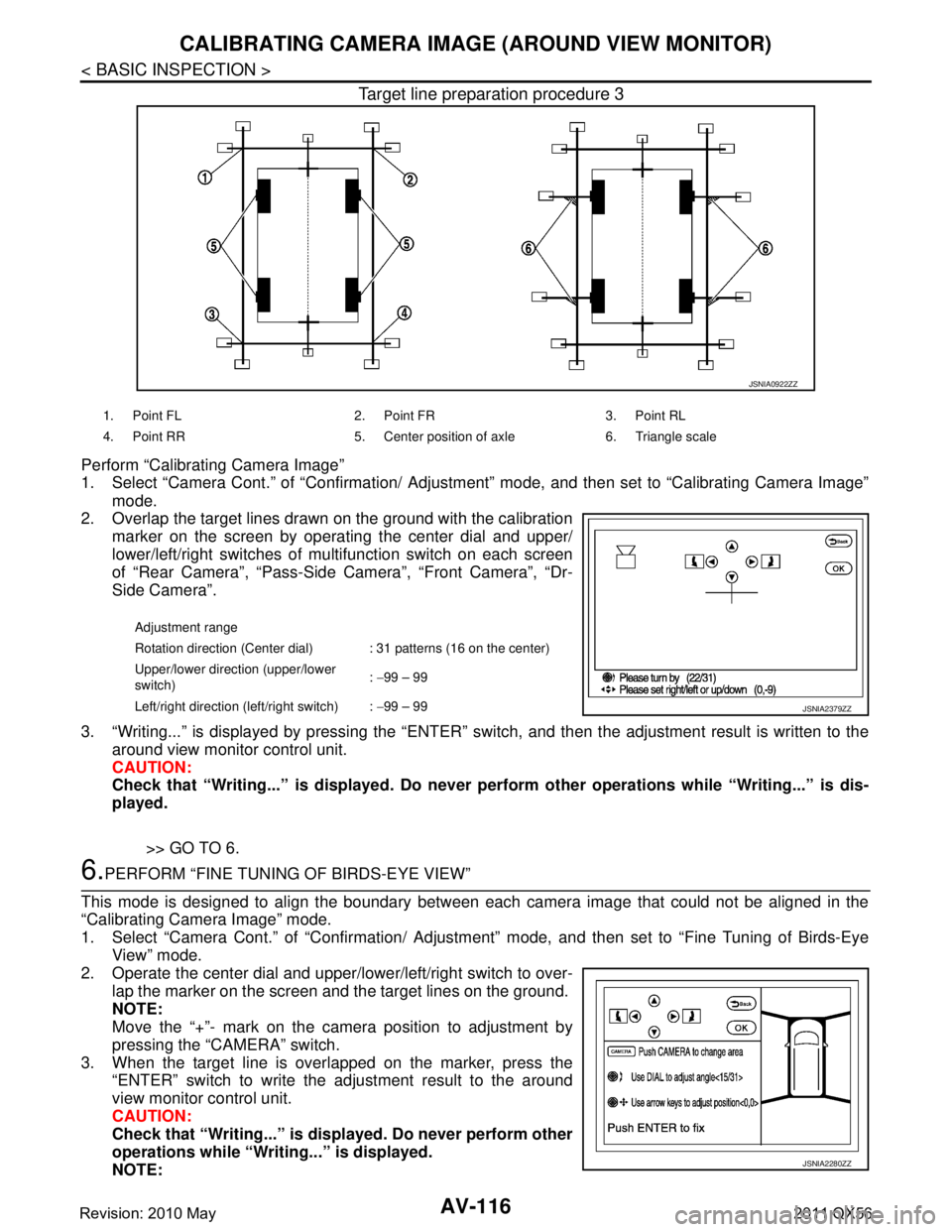
Target line preparation procedure 3
Perform “Calibrating Camera Image”
1. Select “Camera Cont.” of “Confirmation/ Adjustment” mode, and then set to “Calibrating Camera Image”
mode.
2. Overlap the target lines drawn on the ground with the calibration
marker on the screen by operating the center dial and upper/
lower/left/right switches of multifunction switch on each screen
of “Rear Camera”, “Pass-Side Camera”, “Front Camera”, “Dr-
Side Camera”.
3. “Writing...” is displayed by pressing the “ENTER” s witch, and then the adjustment result is written to the
around view monitor control unit.
CAUTION:
Check that “Writing...” is displayed . Do never perform other operations while “Writing...” is dis-
played.
>> GO TO 6.
6.PERFORM “FINE TUNING OF BIRDS-EYE VIEW”
This mode is designed to align the boundary between each camera image that could not be aligned in the
“Calibrating Camera Image” mode.
1. Select “Camera Cont.” of “Confirmation/ Adjustm ent” mode, and then set to “Fine Tuning of Birds-Eye
View” mode.
2. Operate the center dial and upper/l ower/left/right switch to over-
lap the marker on the screen and the target lines on the ground.
NOTE:
Move the “+”- mark on the camera position to adjustment by
pressing the “CAMERA” switch.
3. When the target line is overlapped on the marker, press the “ENTER” switch to write the adjustment result to the around
view monitor control unit.
CAUTION:
Check that “Writing...” is disp layed. Do never perform other
operations while “Writing...” is displayed.
NOTE:
JSNIA0922ZZ
1. Point FL 2. Point FR 3. Point RL
4. Point RR 5. Center position of axle 6. Triangle scale
Adjustment range
Rotation direction (Center dial) : 31 patterns (16 on the center)
Upper/lower direction (upper/lower
switch) :
−99 – 99
Left/right direction (left/right switch) : −99 – 99
JSNIA2379ZZ
JSNIA2280ZZ
Revision: 2010 May2011 QX56
Page 291 of 5598

AV
U1243 FRONT DISPLAY UNITAV-143
< DTC/CIRCUIT DIAGNOSIS >
C
DE
F
G H
I
J
K L
M B A
O P
U1243 FRONT DISPLAY UNIT
DTC LogicINFOID:0000000006216293
Diagnosis ProcedureINFOID:0000000006216294
1.CHECK FRONT DISPLAY UNIT POWER SUPPLY AND GROUND CIRCUITS
Check front display unit power s upply and ground circuits. Refer to AV-161, "
FRONT DISPLAY UNIT : Diagno-
sis Procedure".
Is inspection result normal?
YES >> GO TO 2.
NO >> Repair malfunctioning parts.
2.CHECK CONTINUITY CO MMUNICATION CIRCUITS
1. Turn ignition switch OFF.
2. Disconnect front display unit connector and AV control unit connector.
3. Check continuity between front display unit harness connector and AV control unit harness connector.
4. Check continuity between front display unit harness connector and ground.
Is inspection result normal?
YES >> GO TO 3.
NO >> Repair harness or connector.
3.CHECK COMMUNICATION SIGNAL
1. Connect front display unit connector and AV control unit connector.
2. Turn ignition switch ON.
3. Check signal between front display unit harness connector and ground.
DTC Display contents of
CONSULT-III DTC Detection Condit
ion Possible causes
U1243 FRONT DISP CONN
[U1243] When either one of the following items is detected.
front display unit power supply and ground circuits are
malfunctioning.
serial communication circuits between front display unit and AV control unit are malfunctioning. Front display unit power supply and
ground circuits.
Serial communication circuits be- tween front display unit and AV
control unit.
Front display unit AV control unit Continuity
Connector Terminals Connector Terminals
M215 9
M210 89
Existed
10 73
Front display unit GroundContinuity
Connector Terminals
M215 9
Not existed
10
Revision: 2010 May2011 QX56