brake sensor INFINITI QX56 2011 Factory Service Manual
[x] Cancel search | Manufacturer: INFINITI, Model Year: 2011, Model line: QX56, Model: INFINITI QX56 2011Pages: 5598, PDF Size: 94.53 MB
Page 3883 of 5598
![INFINITI QX56 2011 Factory Service Manual
PCS-42
< SYSTEM DESCRIPTION >[POWER DISTRIBUTION SYSTEM]
DIAGNOSIS SYSTEM (BCM)
SELF-DIAG RESULT
Refer to
BCS-57, "DTCIndex".
DATA MONITOR
PW DOWN SET Unlock button pressing time on Intelligent Key INFINITI QX56 2011 Factory Service Manual
PCS-42
< SYSTEM DESCRIPTION >[POWER DISTRIBUTION SYSTEM]
DIAGNOSIS SYSTEM (BCM)
SELF-DIAG RESULT
Refer to
BCS-57, "DTCIndex".
DATA MONITOR
PW DOWN SET Unlock button pressing time on Intelligent Key](/img/42/57033/w960_57033-3882.png)
PCS-42
< SYSTEM DESCRIPTION >[POWER DISTRIBUTION SYSTEM]
DIAGNOSIS SYSTEM (BCM)
SELF-DIAG RESULT
Refer to
BCS-57, "DTCIndex".
DATA MONITOR
PW DOWN SET Unlock button pressing time on Intelligent Key button can be selected from the following with
this mode
MODE 1: 3 sec
MODE 2: Non-operation
MODE 3: 5 sec
WELCOME LIGHT SELECT Welcome light function mode can be selected from the following with this mode
Puddle/Outside Handle
Room lamp
Head & Tail Lamps (this item is displayed, but cannot be used)
Heart Beat
WELCOME LIGHT OP SET Welcome light function mode can be changed to operation with this mode
On: Operate
Off: Non-operation
Monitor item Description
Monitor Item Condition
REQ SW -DR Indicates [On/Off] condition of door request switch (driver side)
REQ SW -AS Indicates [On/Off] condition of door request switch (passenger side)
REQ SW -BD/TR Indicates [On/Off] condition of back door request switch
PUSH SW Indicates [On/Off] condition of push-button ignition switch
CLUTCH SW NOTE:
This item is displayed, but cannot be monitored
BRAKE SW 1 Indicates [On/Off]* condition of stop lamp switch power supply
BRAKE SW 2 Indicates [On/Off] condition of stop lamp switch
DETE/CANCL SW Indicates [On/Off] condition of P position
SFT PN/N SW Indicates [On/Off] condition of P or N position
S/L -LOCK Indicates [On/Off] condition of steering lock unit (LOCK)
S/L -UNLOCK Indicates [On/Off] condition of steering lock unit (UNLOCK)
S/L RELAY -F/B Indicates [On/Off] condition of steering lock relay
UNLK SEN -DR Indicates [On/Off] condition of driver door UNLOCK status
PUSH SW -IPDM Indicates [On/Off] condition of push-button ignition switch
IGN RLY1 -F/B Indicates [On/Off] condition of ignition relay 1
DETE SW -IPDM Indicates [On/Off] condition of P position
SFT PN -IPDM Indicates [On/Off] condition of P or N position
SFT P -MET Indicates [On/Off] condition of P position
SFT N -MET Indicates [On/Off] condition of N position
ENGINE STATE Indicates [Stop/Stall/Crank/Run] condition of engine states
S/L LOCK-IPDM Indicates [On/Off] condition of steering lock unit (LOCK)
S/L UNLK-IPDM Indicates [On/Off] condition of steering lock unit (UNLOCK)
S/L RELAY-REQ Indicates [On/Off] condition of steering lock relay
VEH SPEED 1 Display the vehicle speed signal received from combination meter by numerical value [Km/h]
VEH SPEED 2 Display the vehi cle speed signal received from ABS or VDC or TCM by numerical value [Km/h]
DOOR STAT-DR Indicates [LOCK/READY/UNLK] condition of unlock sensor
DOOR STAT-AS Indicates [LOCK/READY/UNLK] condition of passenger side door status
ID OK FLAG Indicates [Set/Reset] condition of key ID
PRMT ENG STRT Indicates [Set/Reset] condition of engine start possibility
Revision: 2010 May2011 QX56
Page 4204 of 5598

RAX-8
< REMOVAL AND INSTALLATION >
REAR WHEEL HUB AND HOUSING
b. Using suitable tool, rotate adjuster (1) in the direction (A) toretract and loosen brake shoe.
5. Remove wheel sensor harness. Refer to BRC-135, "
REAR
WHEEL SENSOR : Removal and Installation".
6. Remove parking brake shoe and parking brake cable from back plate. Refer to PB-7, "
Removal and Installation" and PB-5,
"Removal and Installation".
7. Remove height sensor from rear lower link (right side). Refer to EXL-136, "
Removal and Installation".
8. Remove vehicle height sensor from rear lower link (left side). Refer to SCS-98, "
Removal and Installation".
9. Set suitable jack under rear lower link.
10. Remove rear lower link from axle housing. Refer to RSU-8, "
Removal and Installation".
11. Remove coil spring. Refer to RSU-8, "
Removal and Installation".
12. Remove cotter pin and adjusting cap, then loosen wheel hub lock nut.
13. Put matching mark (A) on drive shaft and wheel hub and bearing assembly.
CAUTION:
Use paint or similar substance for matching marks. Never
scratch the surface.
14. Patch wheel hub lock nut with a piece of wood. Hammer the wood to disengage wheel hub and bearing assembly from drive
shaft.
CAUTION:
Never place drive shaft joint at an extreme angle. Also be
careful not to over extend slide joint.
Never allow drive shaft to ha ng down without support for
counterpart such as joint sub-assembly, and other parts.
NOTE:
Use a suitable puller, if wheel hub and bearing assembly and drive shaft cannot be separated even after
performing the above procedure.
15. Remove wheel hub lock nut.
16. Remove suspension arm from axle housing. CAUTION:
Never damage ball joint boot.
17. Remove front lower link from axle housing. CAUTION:
Never damage ball joint boot.
18. Remove axle housing.
19. Remove wheel hub and bearing assembly.
20. Remove anchor block mounting nuts, and then remove anchor block and back plate from axle housing.
21. Remove hub bolts (1) from wheel hub and bearing assembly, using the ball joint remover (A) (commercial service tool).
CAUTION:
Remove hub bolt only when necessary.
Never hammer the hub bolt to avoid impact to the wheel
hub and bearing assembly.
Pull out the hub bolt in a direction perpendicular to the wheel hub and bearing assembly.
22. Perform inspection after removal. Refer to RAX-9, "
Inspection".
INSTALLATION
Note the following, and install in the reverse order of removal.
JPFIB0014ZZ
JPDIG0121ZZ
JPDIF0299ZZ
Revision: 2010 May2011 QX56
Page 4205 of 5598

REAR WHEEL HUB AND HOUSINGRAX-9
< REMOVAL AND INSTALLATION >
CEF
G H
I
J
K L
M A
B
RAX
N
O P
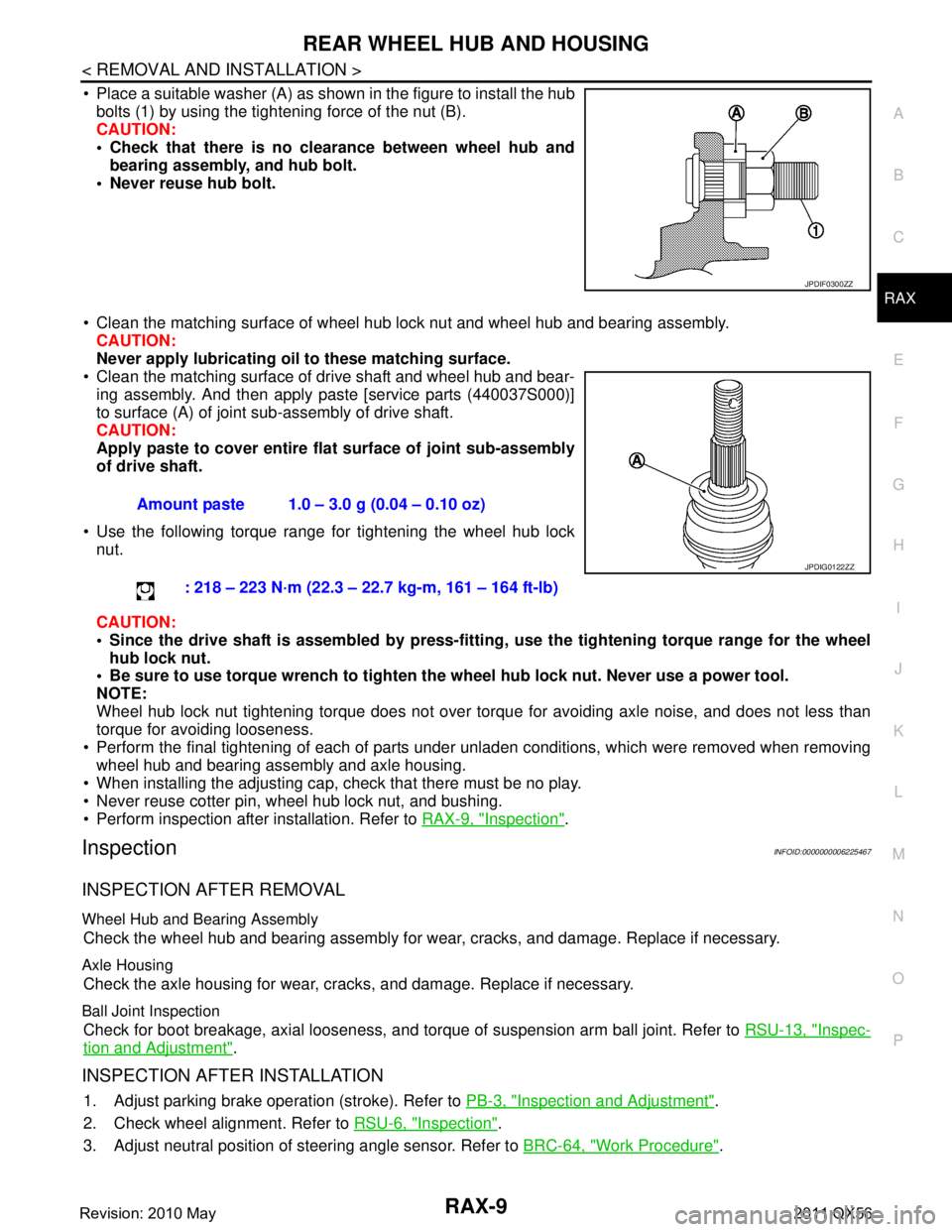
Place a suitable washer (A) as shown in the figure to install the hub bolts (1) by using the tightening force of the nut (B).
CAUTION:
Check that there is no cl earance between wheel hub and
bearing assembly, and hub bolt.
Never reuse hub bolt.
Clean the matching surface of wheel hub lock nut and wheel hub and bearing assembly. CAUTION:
Never apply lubricating oi l to these matching surface.
Clean the matching surface of drive shaft and wheel hub and bear-
ing assembly. And then apply paste [service parts (440037S000)]
to surface (A) of joint sub-assembly of drive shaft.
CAUTION:
Apply paste to cover entire fl at surface of joint sub-assembly
of drive shaft.
Use the following torque range for tightening the wheel hub lock nut.
CAUTION:
Since the drive shaft is assembled by press-fitting , use the tightening torque range for the wheel
hub lock nut.
Be sure to use torque wrench to tighten th e wheel hub lock nut. Never use a power tool.
NOTE:
Wheel hub lock nut tightening torque does not over tor que for avoiding axle noise, and does not less than
torque for avoiding looseness.
Perform the final tightening of each of parts under unladen conditions, which were removed when removing wheel hub and bearing assembly and axle housing.
When installing the adjusting cap, check that there must be no play.
Never reuse cotter pin, wheel hub lock nut, and bushing.
Perform inspection after installation. Refer to RAX-9, "
Inspection".
InspectionINFOID:0000000006225467
INSPECTION AFTER REMOVAL
Wheel Hub and Bearing Assembly
Check the wheel hub and bearing assembly for wear, cracks, and damage. Replace if necessary.
Axle Housing
Check the axle housing for wear, cracks, and damage. Replace if necessary.
Ball Joint Inspection
Check for boot breakage, axial looseness, and torque of suspension arm ball joint. Refer to RSU-13, "Inspec-
tion and Adjustment".
INSPECTION AFTER INSTALLATION
1. Adjust parking brake operation (stroke). Refer to PB-3, "Inspection and Adjustment".
2. Check wheel alignment. Refer to RSU-6, "
Inspection".
3. Adjust neutral position of steering angle sensor. Refer to BRC-64, "
Work Procedure".
JPDIF0300ZZ
Amount paste 1.0 – 3.0 g (0.04 – 0.10 oz)
: 218 – 223 N·m (22.3 – 22.7 kg-m, 161 – 164 ft-lb)
JPDIG0122ZZ
Revision: 2010 May2011 QX56
Page 4207 of 5598

REAR DRIVE SHAFTRAX-11
< REMOVAL AND INSTALLATION >
CEF
G H
I
J
K L
M A
B
RAX
N
O P
REAR DRIVE SHAFT
Exploded ViewINFOID:0000000006225468
Removal and InstallationINFOID:0000000006225469
REMOVAL
1. Remove tire.
2. Remove parking brake cable from suspension member. Refer to PB-5, "
Removal and Installation".
3. Remove wheel sensor harness. Refer to BRC-135, "
REAR WHEEL SENSOR : Removal and Installation".
4. Remove height sensor from rear lower link (right side). Refer to EXL-136, "
Removal and Installation".
5. Remove vehicle height sensor from rear lower link (left side). Refer to SCS-98, "
Removal and Installa-
tion".
6. Set suitable jack under rear lower link.
7. Remove rear lower link (axle housing side). Refer to RSU-8, "
Removal and Installation".
8. Remove coil spring. Refer to RSU-8, "
Removal and Installation".
9. Remove cotter pin and adjusting cap, then loosen wheel hub lock nut. Refer to RAX-7, "
Removal and
Installation".
1. Housing 2. Snap ring 3. Ball cage/steel ball/inner race as-
sembly
4. Stopper ring 5. Boot band 6. Boot
7. Shaft 8. Circular clip 9. Joint sub-assembly
10. Dust shield : Wheel side
1: NISSAN genuine grease or an equivalent.
2: Apply paste [service parts (440037S000)].
Refer to GI-4, "
Components" for symbols not described on the above.
JPDIG0164GB
Revision: 2010 May2011 QX56
Page 4273 of 5598

RSU-18
< UNIT REMOVAL AND INSTALLATION >
REAR SUSPENSION MEMBER
UNIT REMOVAL AND INSTALLATION
REAR SUSPENSION MEMBER
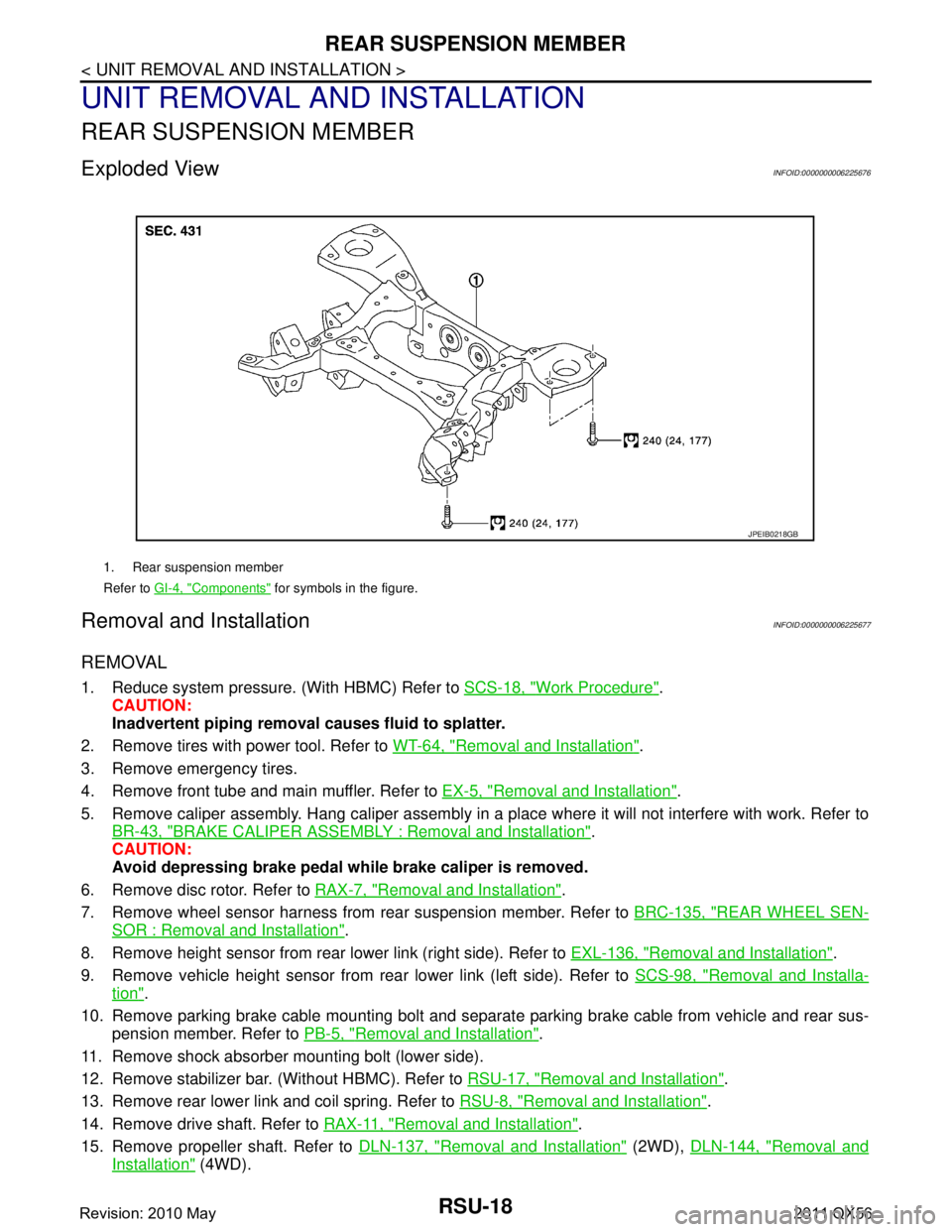
Exploded ViewINFOID:0000000006225676
Removal and InstallationINFOID:0000000006225677
REMOVAL
1. Reduce system pressure. (With HBMC) Refer to SCS-18, "Work Procedure".
CAUTION:
Inadvertent piping removal causes fluid to splatter.
2. Remove tires with power tool. Refer to WT-64, "
Removal and Installation".
3. Remove emergency tires.
4. Remove front tube and main muffler. Refer to EX-5, "
Removal and Installation".
5. Remove caliper assembly. Hang caliper assembly in a place where it will not interfere with work. Refer to BR-43, "
BRAKE CALIPER ASSEMBLY : Removal and Installation".
CAUTION:
Avoid depressing brake pedal wh ile brake caliper is removed.
6. Remove disc rotor. Refer to RAX-7, "
Removal and Installation".
7. Remove wheel sensor harness from rear suspension member. Refer to BRC-135, "
REAR WHEEL SEN-
SOR : Removal and Installation".
8. Remove height sensor from rear lower link (right side). Refer to EXL-136, "
Removal and Installation".
9. Remove vehicle height sensor from rear lower link (left side). Refer to SCS-98, "
Removal and Installa-
tion".
10. Remove parking brake cable mounting bolt and separa te parking brake cable from vehicle and rear sus-
pension member. Refer to PB-5, "
Removal and Installation".
11. Remove shock absorber mounting bolt (lower side).
12. Remove stabilizer bar. (Without HBMC). Refer to RSU-17, "
Removal and Installation".
13. Remove rear lower link and coil spring. Refer to RSU-8, "
Removal and Installation".
14. Remove drive shaft. Refer to RAX-11, "
Removal and Installation".
15. Remove propeller shaft. Refer to DLN-137, "
Removal and Installation" (2WD), DLN-144, "Removal and
Installation" (4WD).
1. Rear suspension member
Refer to GI-4, "
Components" for symbols in the figure.
JPEIB0218GB
Revision: 2010 May2011 QX56
Page 4274 of 5598

REAR SUSPENSION MEMBERRSU-19
< UNIT REMOVAL AND INSTALLATION >
C
DF
G H
I
J
K L
M A
B
RSU
N
O P
16. Remove final drive. Refer to DLN-201, "Removal and Installation".
17. Remove rear tube assembly A and rear tube assembly B. (With HBMC) Refer to SCS-44, "
REAR TUBE
ASSEMBLY : Removal and Installation".
18. Set suitable jack under rear suspension member.
19. Slowly lower jack, then remove rear suspension member, suspension arm, front lower link, wheel hub and housing from vehicle as a unit.
20. Remove mounting bolts and nuts, then remove suspension arm, front lower link, wheel hub and housing from rear suspension member.
21. Perform inspection after removal. Refer to RSU-19, "
Inspection and Adjustment".
INSTALLATION
Note the following, and install in the reverse order of the removal.
Perform the final tightening of each of parts under unladen conditions, which were removed when removing
rear suspension assembly.
Perform inspection after installation. Refer to RSU-19, "
Inspection and Adjustment".
Perform adjustment after installation. (With HBMC) Refer to RSU-19, "
Inspection and Adjustment".
Inspection and AdjustmentINFOID:0000000006225678
INSPECTION AFTER REMOVAL
Check rear suspension member for deformation, cracks, or any other damage. Replace if necessary.
INSPECTION AFTER INSTALLATION
1. Adjust parking brake operation (stroke). Refer to PB-3, "Inspection and Adjustment".
2. Check wheel alignment. Refer to RSU-6, "
Inspection".
3. Adjust neutral position of steering angle sensor. Refer to BRC-64, "
Work Procedure".
4. Adjust levelizer adjustment of height sensor. Refer to EXL-61, "
LEVELIZER ADJUSTMENT : Special
Repair Requirement".
5. Check standard vehicle height setting of vehicle height sensor. Refer to SCS-67, "
Work Procedure".
6. Check wheel sensor harness for proper connection. Refer to BRC-135, "
REAR WHEEL SENSOR :
Exploded View"
ADJUSTMENT AFTER INSTALLATION (WITH HBMC)
Bleed air from the HBMC. Refer to SCS-18, "Work Procedure".
Revision: 2010 May2011 QX56
Page 4299 of 5598

SBC-2
DTC Logic ...............................................................38
Diagnosis Procedure ..............................................38
Component Inspection ............................................39
B2454 SEAT BLT PWR DR CIRC .....................41
DTC Logic ............................................................ ...41
Diagnosis Procedure ..............................................41
B2455 CONTROL UNIT DR ..............................42
DTC Logic ............................................................ ...42
Diagnosis Procedure ..............................................42
B2456 SEAT BLT PWR AS ...............................43
DTC Logic ............................................................ ...43
Diagnosis Procedure ..............................................43
B2457 CONTROL UNIT AS ...............................44
DTC Logic ............................................................ ...44
Diagnosis Procedure ..............................................44
B2458 LOCAL COMM .......................................45
DTC Logic ............................................................ ...45
Diagnosis Procedure ..............................................45
B2461 VHCL SPEED SIGNAL ..........................47
Description ........................................................... ...47
DTC Logic ...............................................................47
Diagnosis Procedure ..............................................47
B2463 ROLLOVER SIGNAL .............................48
Description ........................................................... ...48
DTC Logic ...............................................................48
Diagnosis Procedure ..............................................48
B2466 DR/AS CONTROL UNIT ........................49
DTC Logic ............................................................ ...49
Diagnosis Procedure ..............................................49
B2470 SYS HEAT PROTC DR ..........................50
Description ........................................................... ...50
DTC Logic ...............................................................50
Diagnosis Procedure ..............................................50
B2471 SYS HEAT PROTC AS ..........................51
Description ........................................................... ...51
DTC Logic ...............................................................51
Diagnosis Procedure ............................................ ...51
POWER SUPPLY AND GROUND CIRCUIT .....52
Diagnosis Procedure ............................................ ...52
SEAT BELT BUCKLE SWITCH (DRIVER
SIDE) ..................................................................
53
Component Function Check ................................ ...53
Diagnosis Procedure ...............................................53
Component Inspection [Seat Belt Assembly (Driv-
er Side)] ..................................................................
54
SEAT BELT BUCKLE SWITCH (PASSEN-
GER SIDE) .........................................................
55
Component Function Check ................................ ...55
Diagnosis Procedure ...............................................55
Component Inspection [Seat Belt Assembly (Pas-
senger Side)] ...........................................................
56
SEAT BELT WARNING LAMP CIRCUIT ..........57
Component Function Check ................................ ...57
Diagnosis Procedure ...............................................57
Component Inspection [Seat Belt Assembly (Pas-
senger Side)] ...........................................................
58
SYMPTOM DIAGNOSIS ............................60
PRE-CRASH SEAT BELT DOSE NOT OPER-
ATE ................................................................. ...
60
Diagnosis Procedure ............................................ ...60
SEAT BELT WARNING LAMP DOES NOT
TURN OFF .........................................................
61
Diagnosis Procedure ............................................ ...61
SEAT BELT WARNING LAMP DOES NOT
TURN ON ...........................................................
62
Diagnosis Procedure ............................................ ...62
REMOVAL AND INSTALLATION ..............63
BRAKE PEDAL STROKE SENSOR .............. ...63
Exploded View ..................................................... ...63
Removal and Installation .........................................63
Revision: 2010 May2011 QX56
Page 4302 of 5598

COMPONENT PARTSSBC-5
< SYSTEM DESCRIPTION >
C
DE
F
G
I
J
K L
M A
B
SBC
N
O P
SYSTEM DESCRIPTION
COMPONENT PARTS
Component Parts LocationINFOID:0000000006237875
1. BCM Refer to BCS-4, "
BODY CONTROL
SYSTEM : Componen t Parts Loca-
tion". 2. Combination meter
Refer to MWI-6, "
METER SYSTEM :
Component Parts Location". 3. ABS actuator and electric unit (con-
trol unit)
Refer to BRC-149, "Component
Parts Location".
4. Brake pedal stroke sensor 5. Steering angle sensor Pre-crash 6. Pre-crash seat belt control unit (driver side)
7. ADAS control unit Refer to DAS-13, "
Component Parts
Location". 8. Air bag diagnosis sensor unit
Refer to SRC-8, "
Component Parts
Location". 9. Seat belt control unit (passenger
side)
10. Seat belt buckle switch
JMHIA1582ZZ
Revision: 2010 May2011 QX56
Page 4303 of 5598

SBC-6
< SYSTEM DESCRIPTION >
COMPONENT PARTS
Component Description
INFOID:0000000006237876
A. View with instrument driver lower cov- er removed B. Combination switch C. View with center pillar lower garnish
removed (driver side)
D. View with center pillar lower garnish re- moved (passenger side)
Component Function
ABS actuator and electric unit (control unit) ABS operation signal is rece
ived from ABS actuator and el ectric unit (control unit)
via CAN communication.
ADAS control unit Intelligent brake assistance operation signal is received from ADAS control unit
via CAN communication.
Air bag diagnosis sensor unit Detects a collision and supplies power supply for deployment to air bag module
and pre-tensioner seat belt.
Performs the deploy judgement of passenger air bag based on the information from Occupant Detection System control unit
BCM Ignition ON signal, sleep/wake up signal, and door switch signal are received
from BCM via CAN communication.
Brake pedal stroke sensor It changes voltage according to brake pedal depressed amount and sends the
signal to pre-crash seat belt control unit.
There are 2 signals (brake pedal stroke sensor 1 and 2) sent from the brake
pedal stroke sensor. Pre-crash seat belt control unit judges the stroke amount
and the speed of the brake pedal according to the voltage of the signal sent by
each side.
Combination meter Transmits vehicle speed signal to pre-crash seat belt control unit (driver side).
Turns the seat belt warning lamp ON when the seat belt is unfastened.
Occupant detection system control unit Judges the passenger seat condition based on the information from occupant de-
tection unit.
Pre-crush seat belt control unit (driver side) Total control of pre-crash seat belt system is operated according to transmit sig-
nal.
Driver seat belt retractor integrates pre-crash seat belt control unit (driver side), driver seat belt motor, and tension reducer.
Seat belt motor operates each operation of pull, return, and hold.
Pre-crush seat belt control unit (passenger side) Control of passenger pre-crash seat belt is operated according to transmit sig-
nal.
Passenger seat belt retractor integrates pre-crash seat belt control unit (driver seat), driver seat belt motor, and tension reducer.
Seat belt motor operates each operation of pull, return, and hold.
Seat belt buckle switch (driver side) Fastening or not fastening of seat belt is judged. This judgment is used for con-
trol of driver pre-crash seat belt system.
Seat belt warning lamp on combination meter turns ON when seat belt is not fastened while ignition switch is ON.
The seat belt buckle switch is installed in the seat belt buckle.
Seat belt buckle switch (passenger side) Fastening or not fastening of seat belt is judged. This judgment is used to con-
trol passenger pre-crash seat belt system.
The seat belt buckle switch is installed in the seat belt buckle.
Steering angle sensor Steering angle sensor signal, steering angle speed signal, steering angle sensor
neutral position adjustment completion signal, and steering angle sensor mal-
function signal are received via CAN communication.
Revision: 2010 May2011 QX56
Page 4308 of 5598

DIAGNOSIS SYSTEM (PRE-CRASH SEAT BELT)SBC-11
< SYSTEM DESCRIPTION >
C
DE
F
G
I
J
K L
M A
B
SBC
N
O P
DIAGNOSIS SYSTEM (P RE-CRASH SEAT BELT)
CONSULT-III FunctionINFOID:0000000006237882
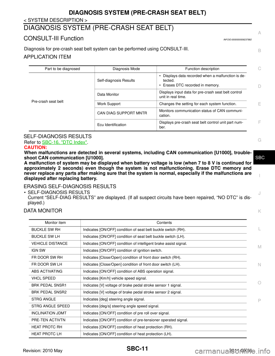
Diagnosis for pre-crash seat belt syst em can be performed using CONSULT-III.
APPLICATION ITEM
SELF-DIAGNOSIS RESULTS
Refer to SBC-16, "DTC Index".
CAUTION:
When malfunctions are detect ed in several systems, includin g CAN communication [U1000], trouble-
shoot CAN communication [U1000].
A malfunction of system may be disp layed when battery voltage is low (when 7 to 8 V is continued for
approximately 2 seconds) even though the system is not malfunctioning. Erase DTC memory and
never replace any parts after making sure that the syst em is normal, especially if the malfunctions are
displayed after replacing battery.
ERASING SELF-DIAGNOSIS RESULTS
SELF-DIAGNOSIS RESULTS Current “SELF-DIAG RESULTS” are displayed. (If all suspect circuits have been repaired, “NO DTC” is dis-
played.)
DATA MONITOR
Part to be diagnosed Diagnosis Mode Function description
Pre-crash seat belt Self-diagnosis Results
Displays data recorded when a malfunction is de-
tected.
Erases DTC recorded in memory.
Data Monitor Displays input data for pre-crash seat belt control
unit in real time.
Work Support Changes the setting for each system function.
CAN DIAG SUPPORT MNTR Monitors communication status of CAN communi-
cation.
Ecu Identification Displays pre-crash seat belt control unit part num-
ber.
Monitor item Contents
BUCKLE SW RH Indicates [ON/OFF] condition of seat belt buckle switch (RH).
BUCKLE SW LH Indicates [ON/OFF] condition of seat belt buckle switch (LH).
VEHICLE DISTANCE Indicates [ON/OFF] condit ion of intelligent brake assist signal.
IGN SW Indicates [ON/OFF] condition of ignition switch.
FR DOOR SW RH Indicates [Close/Open] condition of front door switch (RH).
FR DOOR SW LH Indicates [Close/Open] condition of front door switch (LH).
ABS ACTIVATING Indicates [ON/OFF] co ndition of ABS operation signal.
VHCL SPEED Indicates [Km/h] vehicle speed signal.
BRK PEDAL SNSR1 Indicates [V] voltage of brake pedal stroke sensor 1 signal.
BRK PEDAL SNSR2 Indicates [V] voltage of brake pedal stroke sensor 2 signal.
STRG ANGLE Indicates [deg] steering angle signal.
STRG ANGLE SPEED Indicates [deg/s] steering angle speed signal.
INCLINATION JDMT Indicates [ON/OFF] condition of pre roll over signal.
PRE-TEN ACTIVTN Indicates [ON/OFF] condition of pre-tensioner operated signal.
HEAT PROTC RH Indicates [ON/OFF] condition of heat protection (RH).
HEAT PROTC LH Indicates [ON/OFF] condition of heat protection (LH).
Revision: 2010 May2011 QX56