Fuel INFINITI QX56 2011 Factory Service Manual
[x] Cancel search | Manufacturer: INFINITI, Model Year: 2011, Model line: QX56, Model: INFINITI QX56 2011Pages: 5598, PDF Size: 94.53 MB
Page 2566 of 5598

EM-4
< PRECAUTION >
PRECAUTIONS
If turning the steering wheel is required with the battery disconnected or discharged, follow the operation pro-
cedure below before starting the repair operation.
OPERATION PROCEDURE
1. Connect both battery cables.
NOTE:
Supply power using jumper cables if battery is discharged.
2. Turn the push-button ignition switch to ACC position. (At this time, the steering lock will be released.)
3. Disconnect both battery cables. The steering lock wi ll remain released with both battery cables discon-
nected and the steering wheel can be turned.
4. Perform the necessary repair operation.
5. When the repair work is completed, re-connect bot h battery cables. With the brake pedal released, turn
the push-button ignition switch from ACC position to ON position, then to LOCK position. (The steering
wheel will lock when the push-button igniti on switch is turned to LOCK position.)
6. Perform self-diagnosis check of all control units using CONSULT-III.
Precaution for Drain Engine Coolant and Engine OilINFOID:0000000006289509
Drain engine coolant and engine oil when engine is cooled.
Precaution for Disconnecting Fuel PipingINFOID:0000000006289510
Before starting work, check no fire or sp ark producing items are in the work area.
Release fuel pressure before disconnecting and disassembly.
After disconnecting pipes, plug openings to stop fuel leakage.
Precaution for Handling High Pressure Fuel SystemINFOID:0000000006289511
High pressure fuel system components are betw een high pressure fuel pump and fuel injector.
Always release fuel pressure and never start the engine when performing removal and installation.
When removing or installing parts without releasing fuel pressure, fuel may be splashed and, if fuel contacts
skin or eyes, it may cause inflammation.
Precaution for Removal and DisassemblyINFOID:0000000006289512
When instructed to use SST, use specified tools. Always be careful to work safely, avoid forceful or unin-
structed operations.
Exercise maximum care to avoid damage to mating or sliding surfaces.
Cover openings of engine system with tape or the equival ent, if necessary, to seal out foreign materials.
Mark and arrange disassembly parts in an organi zed way for easy troubleshooting and assembly.
When loosening nuts and bolts, as a basic rule, star t with the one furthest outside, then the one diagonally
opposite, and so on. If the order of loosening is specified, do exactly as specified. Power tools may be used
where noted in the step.
Precaution for Inspection, Repair and ReplacementINFOID:0000000006289513
Before repairing or replacing, thoroughly inspect parts. Inspect new replacement parts in the same way, and
replace if necessary.
Precaution for Assembly and InstallationINFOID:0000000006289514
Use torque wrench to tighten bolts or nuts to specification.
When tightening nuts and bolts, as a basic rule, equally tighten in several different steps starting with the
ones in center, then ones on inside and outside diagonally in this order. If the order of tightening is specified,
do exactly as specified.
Replace with new gasket, packing, oil seal or O-ring.
Thoroughly wash, clean, and air-blow each part. Carefully check engine oil or engine coolant passages for
any restriction and blockage.
Dowel pins are used for several parts alignment. When replacing and reassembling parts with dowel pins,
check that dowel pins are installed in the original position.
Revision: 2010 May2011 QX56
Page 2567 of 5598
PRECAUTIONSEM-5
< PRECAUTION >
C
DE
F
G H
I
J
K L
M A
EM
NP
O
Avoid damaging sliding or mating surfaces. Completely re
move foreign materials such as cloth lint or dust.
Before assembly, oil sliding surfaces well.
Release air within route when refilling after draining engine coolant.
After repairing, start engine and increase engine speed to check engine coolant, fuel, engine oil, and
exhaust gases for leakage.
Parts Requiring Angle TighteningINFOID:0000000006289515
Use angle wrench [SST: KV10112100 (BT8653-A)] for the final tightening of the following engine parts:
- Cylinder head bolts
- Main bearing cap bolts
- Main bearing cap sub bolts
- Connecting rod cap bolts
- Crankshaft pulley bolt (No angle wrench is required as the bolt flange is provided with notches for angletightening)
Ensure thread and seat surfaces are clean and coated with engine oil.
Precaution for Liquid GasketINFOID:0000000006289516
REMOVAL OF LIQUID GASKET SEALING
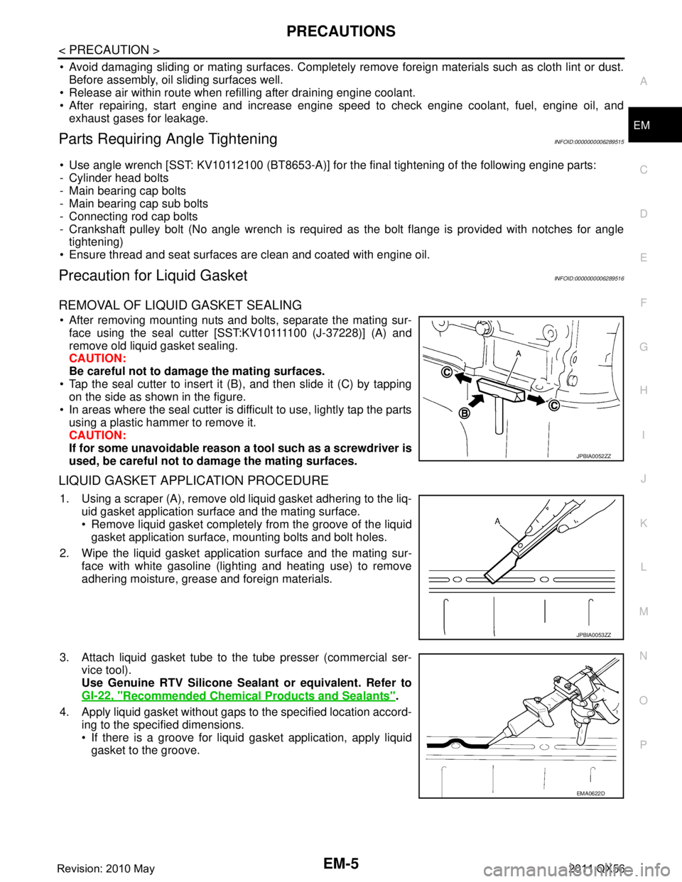
After removing mounting nuts and bolts, separate the mating sur- face using the seal cutter [SST:KV10111100 (J-37228)] (A) and
remove old liquid gasket sealing.
CAUTION:
Be careful not to damage the mating surfaces.
Tap the seal cutter to insert it (B), and then slide it (C) by tapping on the side as shown in the figure.
In areas where the seal cutter is difficult to use, lightly tap the parts using a plastic hammer to remove it.
CAUTION:
If for some unavoidable reason a tool such as a screwdriver is
used, be careful not to damage the mating surfaces.
LIQUID GASKET APPLICATION PROCEDURE
1. Using a scraper (A), remove old liquid gasket adhering to the liq- uid gasket application surface and the mating surface.
Remove liquid gasket completely from the groove of the liquidgasket application surface, mounting bolts and bolt holes.
2. Wipe the liquid gasket application surface and the mating sur- face with white gasoline (lighting and heating use) to remove
adhering moisture, grease and foreign materials.
3. Attach liquid gasket tube to the tube presser (commercial ser- vice tool).
Use Genuine RTV Silicone Seal ant or equivalent. Refer to
GI-22, "
Recommended Chemical Products and Sealants".
4. Apply liquid gasket without gaps to the specified location accord- ing to the specified dimensions.
If there is a groove for liquid gasket application, apply liquidgasket to the groove.
JPBIA0052ZZ
JPBIA0053ZZ
EMA0622D
Revision: 2010 May2011 QX56
Page 2570 of 5598
EM-8
< PREPARATION >
PREPARATION
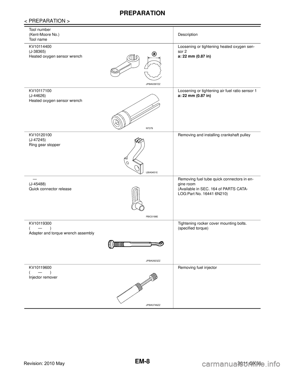
KV10114400
(J-38365)
Heated oxygen sensor wrenchLoosening or tightening heated oxygen sen-
sor 2
a: 22 mm (0.87 in)
KV10117100
(J-44626)
Heated oxygen sensor wrench Loosening or tightening air fuel ratio sensor 1
a: 22 mm (0.87 in)
KV10120100
(J-47245)
Ring gear stopper Removing and installing crankshaft pulley
—
(J-45488)
Quick connector release Removing fuel tube quick connectors in en-
gine room
(Available in SEC. 164 of PARTS CATA-
LOG:Part No. 16441 6N210)
KV10119300
(—)
Adapter and torque wrench assembly Tightening rocker cover mounting bolts.
(specified torque)
KV10119600
(—)
Injector remover Removing fuel injector
Tool number
(Kent-Moore No.)
Tool name
Description
JPBIA0397ZZ
NT379
LBIA0451E
PBIC0198E
JPBIA2623ZZ
JPBIA3746ZZ
Revision: 2010 May2011 QX56
Page 2571 of 5598
PREPARATIONEM-9
< PREPARATION >
C
DE
F
G H
I
J
K L
M A
EM
NP
O
Commercial Service ToolINFOID:0000000006289519
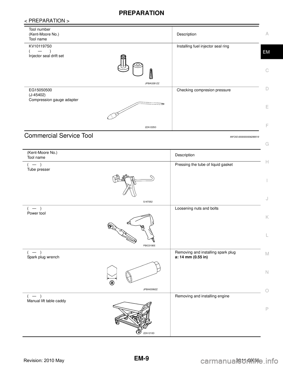
KV101197S0
(—)
Injector seal drift set
Installing fuel injector seal ring
EG15050500
(J-45402)
Compression gauge adapter Checking compresion pressure
Tool number
(Kent-Moore No.)
Tool name
Description
JPBIA3281ZZ
ZZA1225D
(Kent-Moore No.)
Tool name
Description
(—)
Tube presser Pressing the tube of liquid gasket
(—)
Power tool Loosening nuts and bolts
(—)
Spark plug wrench Removing and installing spark plug
a: 14 mm (0.55 in)
(—)
Manual lift table caddy Removing and installing engine
S-NT052
PBIC0190E
JPBIA0399ZZ
ZZA1210D
Revision: 2010 May2011 QX56
Page 2572 of 5598
EM-10
< PREPARATION >
PREPARATION
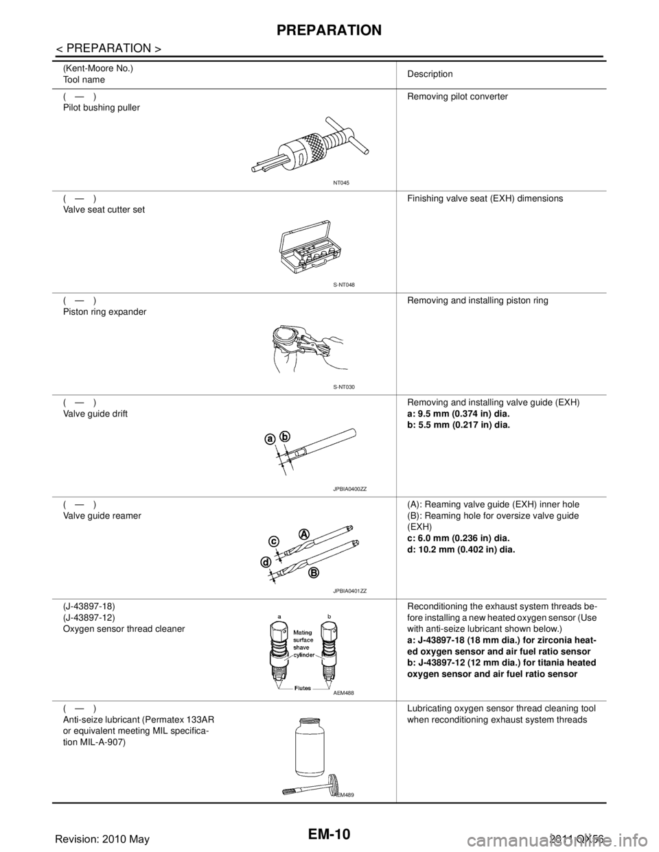
(—)
Pilot bushing pullerRemoving pilot converter
(—)
Valve seat cutter set Finishing valve seat (EXH) dimensions
(—)
Piston ring expander Removing and installing piston ring
(—)
Valve guide drift Removing and installing valve guide (EXH)
a: 9.5 mm (0.374 in) dia.
b: 5.5 mm (0.217 in) dia.
(—)
Valve guide reamer (A): Reaming valve guide (EXH) inner hole
(B): Reaming hole for oversize valve guide
(EXH)
c: 6.0 mm (0.236 in) dia.
d: 10.2 mm (0.402 in) dia.
(J-43897-18)
(J-43897-12)
Oxygen sensor thread cleaner Reconditioning the exhaust system threads be-
fore installing a new heated oxygen sensor (Use
with anti-seize lubricant shown below.)
a: J-43897-18 (18 mm dia.) for zirconia heat-
ed oxygen sensor and air fuel ratio sensor
b: J-43897-12 (12 mm dia.) for titania heated
oxygen sensor and air fuel ratio sensor
(—)
Anti-seize lubricant (Permatex 133AR
or equivalent meeting MIL specifica-
tion MIL-A-907) Lubricating oxygen sensor thread cleaning tool
when reconditioning exhaust system threads
(Kent-Moore No.)
Tool name
Description
NT045
S-NT048
S-NT030
JPBIA0400ZZ
JPBIA0401ZZ
AEM488
AEM489
Revision: 2010 May2011 QX56
Page 2578 of 5598
EM-16
< BASIC INSPECTION >
COMPRESSION PRESSURE
COMPRESSION PRESSURE
InspectionINFOID:0000000006289521
1. Warm up engine thoroughly. Then, stop it.
2. Release fuel pressure. Refer to EC-153, "
Work Procedure".
CAUTION:
If CONSULT-III is not used to release fuel pr essure leave the fuel pump fuse disconnected until
step 7.
3. Remove fuel pump fuse in IPDM E/R. NOTE:
For the fuse number, refer to EC-114, "
Wiring Diagram".
For the fuse arrangement, refer to PG-143, "
Fuse, Connector and Terminal Arrangement".
4. Remove engine cover. Refer to EM-25, "
Exploded View".
5. Remove ignition coil and spark plug from each cylinder. Refer to EM-29, "
Exploded View".
6. Connect engine tachometer (not required in use of CONSULT-III).
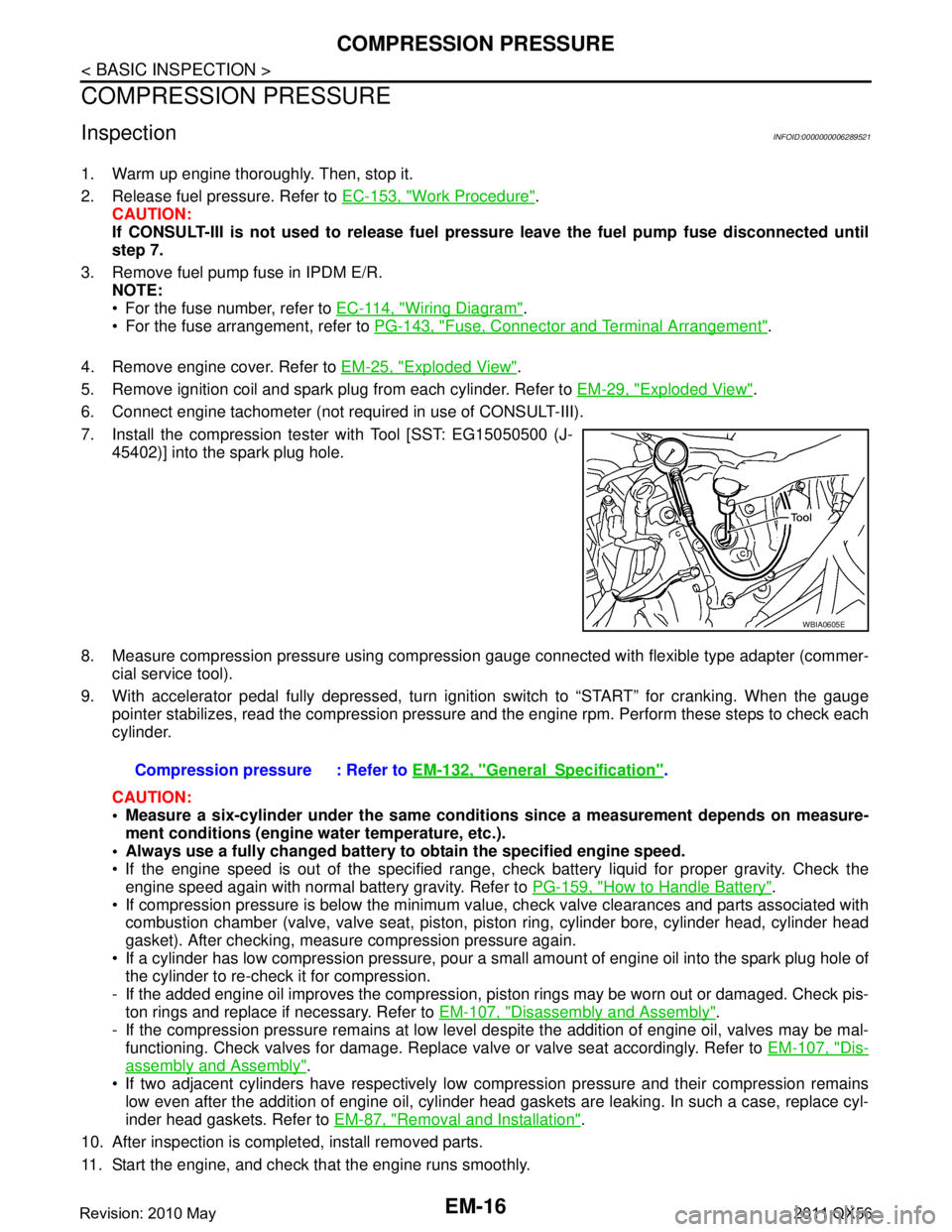
7. Install the compression tester with Tool [SST: EG15050500 (J- 45402)] into the spark plug hole.
8. Measure compression pressure using compressi on gauge connected with flexible type adapter (commer-
cial service tool).
9. With accelerator pedal fully depressed, turn ignition switch to “START” for cranking. When the gauge pointer stabilizes, read the compression pressure and the engine rpm. Perform these steps to check each
cylinder.
CAUTION:
Measure a six-cylinder under the same conditio ns since a measurement depends on measure-
ment conditions (engine water temperature, etc.).
Always use a fully changed battery to obtain the specified engine speed.
If the engine speed is out of the specified range, c heck battery liquid for proper gravity. Check the
engine speed again with normal battery gravity. Refer to PG-159, "
How to Handle Battery".
If compression pressure is below the minimum value, check valve clearances and parts associated with combustion chamber (valve, valve seat, piston, pi ston ring, cylinder bore, cylinder head, cylinder head
gasket). After checking, measure compression pressure again.
If a cylinder has low compression pressure, pour a small amount of engine oil into the spark plug hole of the cylinder to re-check it for compression.
- If the added engine oil improves the compression, pi ston rings may be worn out or damaged. Check pis-
ton rings and replace if necessary. Refer to EM-107, "
Disassembly and Assembly".
- If the compression pressure remains at low level despite the addition of engine oil, valves may be mal- functioning. Check valves for damage. Replace valve or valve seat accordingly. Refer to EM-107, "
Dis-
assembly and Assembly".
If two adjacent cylinders have respectively low co mpression pressure and their compression remains
low even after the addition of engine oil, cylinder head gaskets are leaking. In such a case, replace cyl-
inder head gaskets. Refer to EM-87, "
Removal and Installation".
10. After inspection is completed, install removed parts.
11. Start the engine, and check that the engine runs smoothly.
WBIA0605E
Compression pressure : Refer to EM-132, "GeneralSpecification".
Revision: 2010 May2011 QX56
Page 2595 of 5598
ROCKER COVEREM-33
< REMOVAL AND INSTALLATION >
C
DE
F
G H
I
J
K L
M A
EM
NP
O
ROCKER COVER
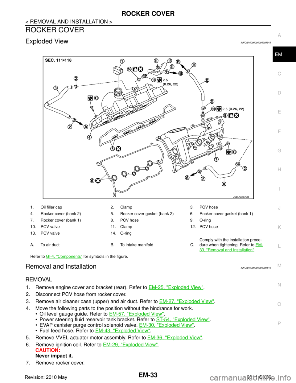
Exploded ViewINFOID:0000000006289545
Removal and InstallationINFOID:0000000006289546
REMOVAL
1. Remove engine cover and bracket (rear). Refer to
EM-25, "Exploded View".
2. Disconnect PCV hose from rocker cover.
3. Remove air cleaner case (upper) and air duct. Refer to EM-27, "
Exploded View".
4. Move the following parts to the position without the hindrance for work. Oil level gauge guide. Refer to EM-57, "
Exploded View".
Power steering fluid reservoir tank bracket. Refer to ST-54, "
Exploded View".
EVAP canister purge control solenoid valve. EM-30, "
Exploded View".
Fuel feed hose. Refer to EM-43, "
Exploded View".
5. Remove VVEL actuator motor assembly. Refer to EM-36, "
Exploded View".
6. Remove ignition coil. Refer to EM-29, "
Exploded View".
CAUTION:
Never impact it.
7. Remove rocker cover.
1. Oil filler cap 2. Clamp 3. PCV hose
4. Rocker cover (bank 2) 5. Rocker cover gasket (bank 2) 6. Rocker cover gasket (bank 1)
7. Rocker cover (bank 1) 8. PCV hose 9. O-ring
10. PCV valve 11. Clamp 12. PCV hose
13. PCV valve 14. O-ring
A. To air duct B. To intake manifold C. Comply with the installation proce-
dure when tightening. Refer to
EM-
33, "Removal and Installation".
Refer to GI-4, "
Components" for symbols in the figure.
JSBIA0387GB
Revision: 2010 May2011 QX56
Page 2602 of 5598
EM-40
< REMOVAL AND INSTALLATION >
EXHAUST MANIFOLD AND THREE WAY CATALYST
EXHAUST MANIFOLD AND THREE WAY CATALYST
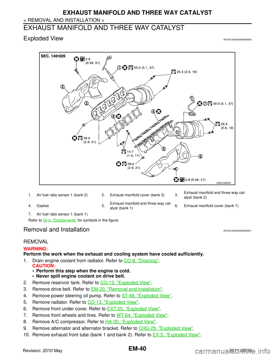
Exploded ViewINFOID:0000000006289550
Removal and InstallationINFOID:0000000006289551
REMOVAL
WARNING:
Perform the work when the exhaust and cooling system have cooled sufficiently.
1. Drain engine coolant from radiator. Refer to CO-8, "
Draining".
CAUTION:
Perform this step when the engine is cold.
Never spill engine coolant on drive belt.
2. Remove reservoir tank. Refer to CO-13, "
Exploded View".
3. Remove drive belt. Refer to EM-20, "
Removal and Installation".
4. Remove power steering oil pump. Refer to ST-48, "
Exploded View".
5. Remove radiator. Refer to CO-13, "
Exploded View".
6. Remove front under cover. Refer to EXT-25, "
Exploded View".
7. Remove front wheels and tires. Refer to WT-64, "
Exploded View".
8. Remove A/C compressor. Refer to HA-30, "
Exploded View".
9. Remove alternator and alternator bracket. Refer to CHG-25, "
Exploded View".
10. Remove exhaust front tube (bank 1 and bank 2). Refer to EX-5, "
Exploded View".
1. Air fuel ratio sensor 1 (bank 2) 2. Exhaust manifold cover (bank 2) 3. Exhaust manifold and three way cat-
alyst (bank 2)
4. Gasket 5. Exhaust manifold and three way cat-
alyst (bank 1)6. Exhaust manifold cover (bank 1)
7. Air fuel ratio sensor 1 (bank 1)
Refer to GI-4, "
Components" for symbols in the figure.
JSBIA0389GB
Revision: 2010 May2011 QX56
Page 2603 of 5598
EXHAUST MANIFOLD AND THREE WAY CATALYST
EM-41
< REMOVAL AND INSTALLATION >
C
D E
F
G H
I
J
K L
M A
EM
NP
O
11. Remove front propeller shaft. Refer to
DLN-128, "Exploded View".
12. Disconnect steering lower joint. Refer to ST-37, "
Exploded View".
13. Remove air fuel ratio sensor 1 as per the following: CAUTION:
Air fuel ratio sensor 1 is not reusable. Never remo ve air fuel ratio sensor 1 unless this is required.
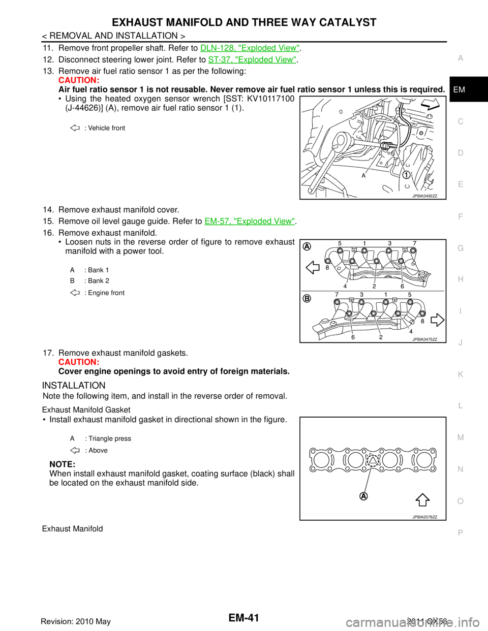
Using the heated oxygen sensor wrench [SST: KV10117100
(J-44626)] (A), remove air fuel ratio sensor 1 (1).
14. Remove exhaust manifold cover.
15. Remove oil level gauge guide. Refer to EM-57, "
Exploded View".
16. Remove exhaust manifold. Loosen nuts in the reverse order of figure to remove exhaustmanifold with a power tool.
17. Remove exhaust manifold gaskets. CAUTION:
Cover engine openings to avoid entry of foreign materials.
INSTALLATION
Note the following item, and install in the reverse order of removal.
Exhaust Manifold Gasket
Install exhaust manifold gasket in directional shown in the figure.
NOTE:
When install exhaust manifold gasket, coating surface (black) shall
be located on the exhaust manifold side.
Exhaust Manifold
: Vehicle front
JPBIA3492ZZ
A : Bank 1
B : Bank 2 : Engine front
JPBIA3475ZZ
A : Triangle press : Above
JPBIA2078ZZ
Revision: 2010 May2011 QX56
Page 2604 of 5598
EM-42
< REMOVAL AND INSTALLATION >
EXHAUST MANIFOLD AND THREE WAY CATALYST
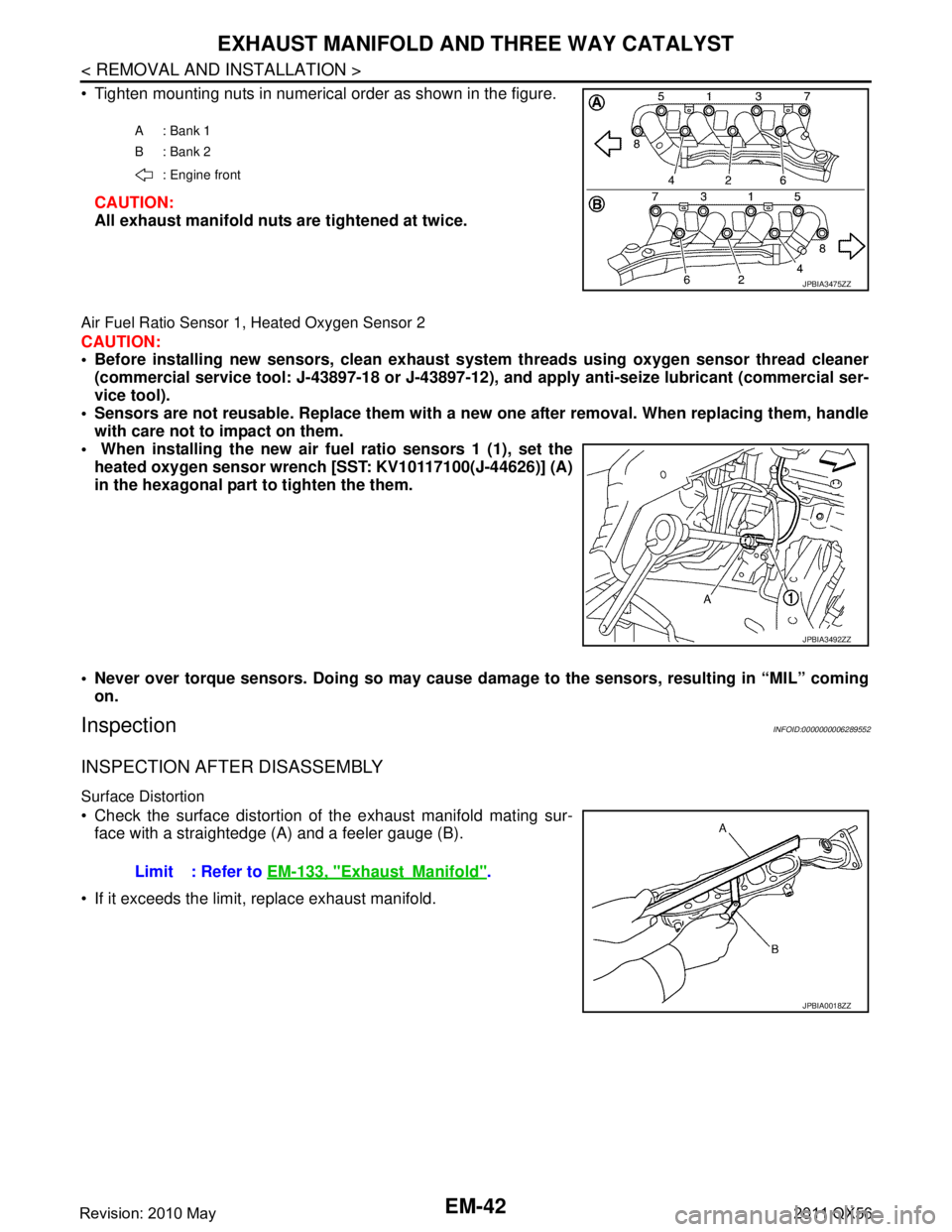
Tighten mounting nuts in numerical order as shown in the figure.CAUTION:
All exhaust manifold nuts are tightened at twice.
Air Fuel Ratio Sensor 1, Heated Oxygen Sensor 2
CAUTION:
Before installing new sensors, clean exhaust system threads usin g oxygen sensor thread cleaner
(commercial service tool: J-43897-18 or J-43897-12), and apply anti-seize lubricant (commercial ser-
vice tool).
Sensors are not reusable. Replace them with a ne w one after removal. When replacing them, handle
with care not to impact on them.
When installing the new air fu el ratio sensors 1 (1), set the
heated oxygen sensor wren ch [SST: KV10117100(J-44626)] (A)
in the hexagonal part to tighten the them.
Never over torque sensors. Doing so may cause da mage to the sensors, resulting in “MIL” coming
on.
InspectionINFOID:0000000006289552
INSPECTION AFTER DISASSEMBLY
Surface Distortion
Check the surface distortion of the exhaust manifold mating sur- face with a straightedge (A) and a feeler gauge (B).
If it exceeds the limit, replace exhaust manifold.
A: Bank 1
B: Bank 2 : Engine front
JPBIA3475ZZ
JPBIA3492ZZ
Limit : Refer to EM-133, "ExhaustManifold".
JPBIA0018ZZ
Revision: 2010 May2011 QX56