INFINITI QX56 2011 Factory Service Manual
QX56 2011
INFINITI
INFINITI
https://www.carmanualsonline.info/img/42/57033/w960_57033-0.png
INFINITI QX56 2011 Factory Service Manual
Trending: Head lamp, lights, change time, low oil pressure, P1557, remote start, boot
Page 691 of 5598
BRM-16
< REMOVAL AND INSTALLATION >
CORROSION PROTECTION
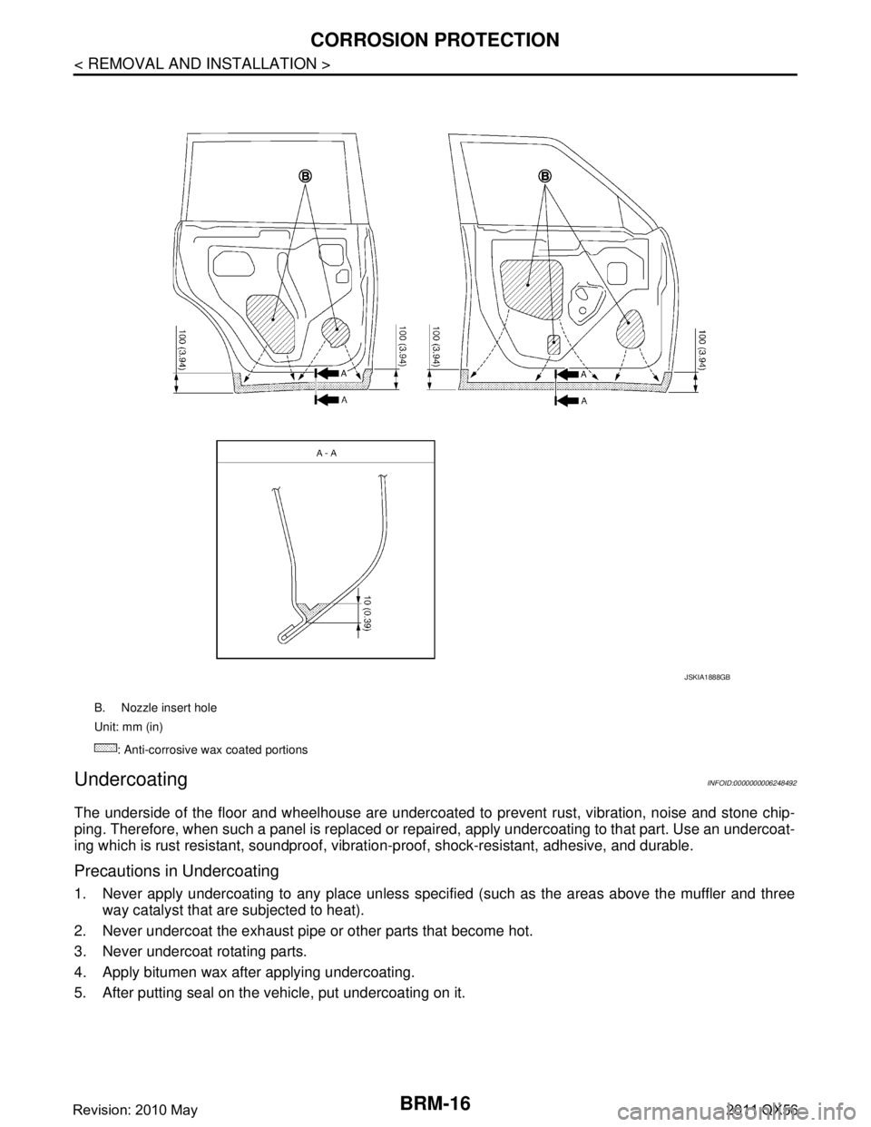
Undercoating
INFOID:0000000006248492
The underside of the floor and wheelhouse are undercoated to prevent rust, vibration, noise and stone chip-
ping. Therefore, when such a panel is replaced or re paired, apply undercoating to that part. Use an undercoat-
ing which is rust resistant, soundproof, vibr ation-proof, shock-resistant, adhesive, and durable.
Precautions in Undercoating
1. Never apply undercoating to any place unless specif ied (such as the areas above the muffler and three
way catalyst that are subjected to heat).
2. Never undercoat the exhaust pipe or other parts that become hot.
3. Never undercoat rotating parts.
4. Apply bitumen wax after applying undercoating.
5. After putting seal on the vehicle, put undercoating on it.
B. Nozzle insert hole
Unit: mm (in)
: Anti-corrosive wax coated portions
JSKIA1888GB
Revision: 2010 May2011 QX56
Page 692 of 5598
CORROSION PROTECTIONBRM-17
< REMOVAL AND INSTALLATION >
C
DE
F
G H
I
J
L
M A
B
BRM
N
O P
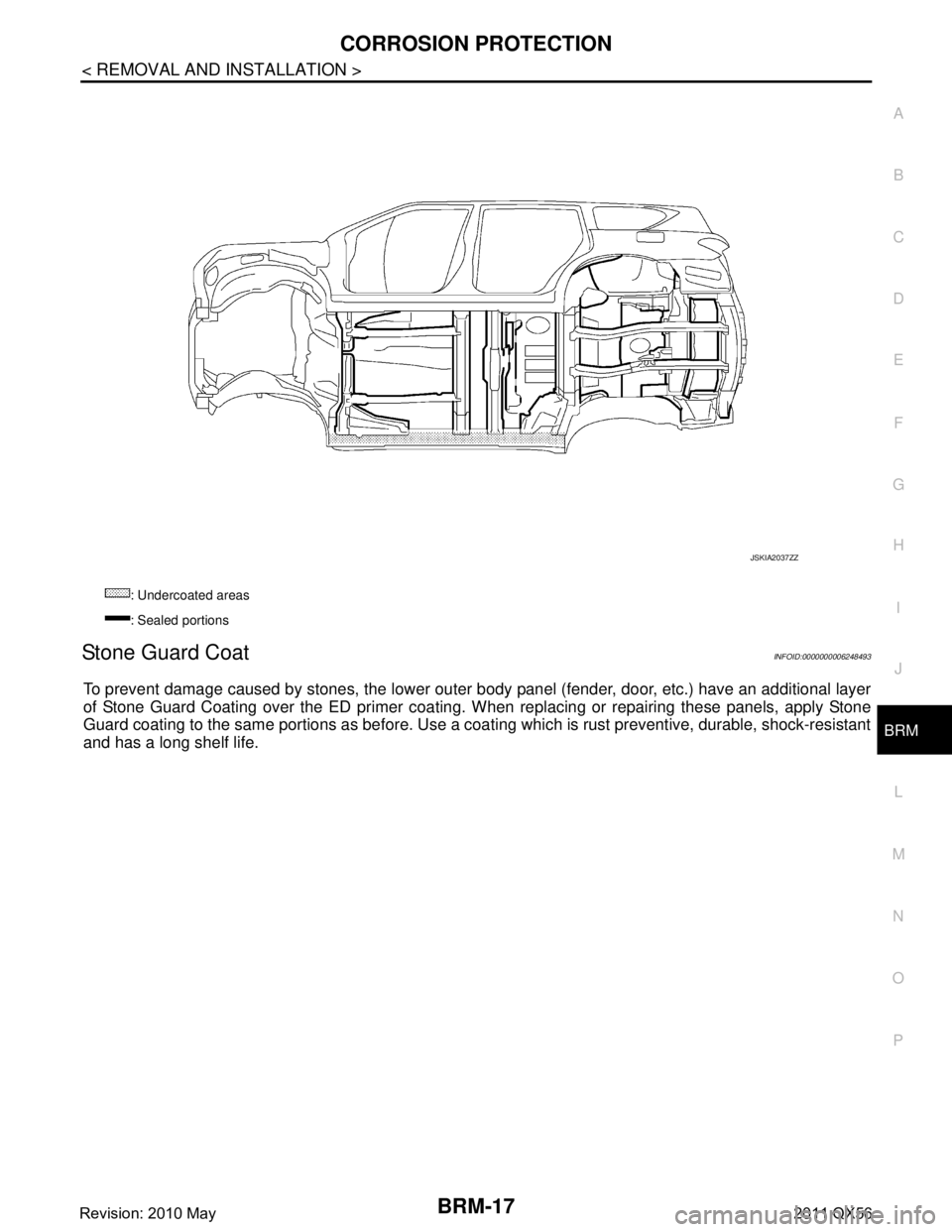
Stone Guard CoatINFOID:0000000006248493
To prevent damage caused by stones, the lower outer body panel (fender, door, etc.) have an additional layer
of Stone Guard Coating over the ED primer coating. When replacing or repairing these panels, apply Stone
Guard coating to the same portions as before. Use a c oating which is rust preventive, durable, shock-resistant
and has a long shelf life.
: Undercoated areas
: Sealed portions
JSKIA2037ZZ
Revision: 2010 May2011 QX56
Page 693 of 5598
BRM-18
< REMOVAL AND INSTALLATION >
CORROSION PROTECTION
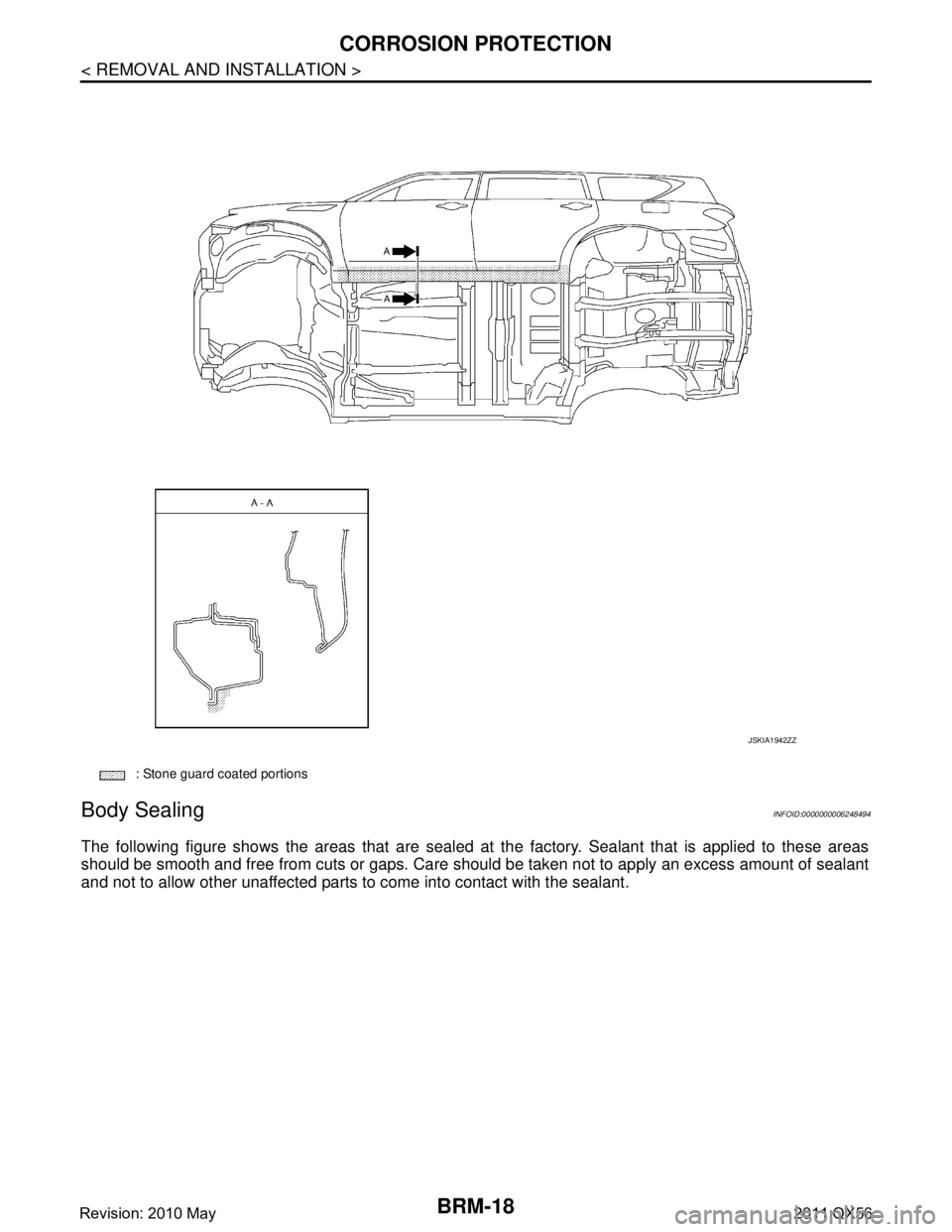
Body Sealing
INFOID:0000000006248494
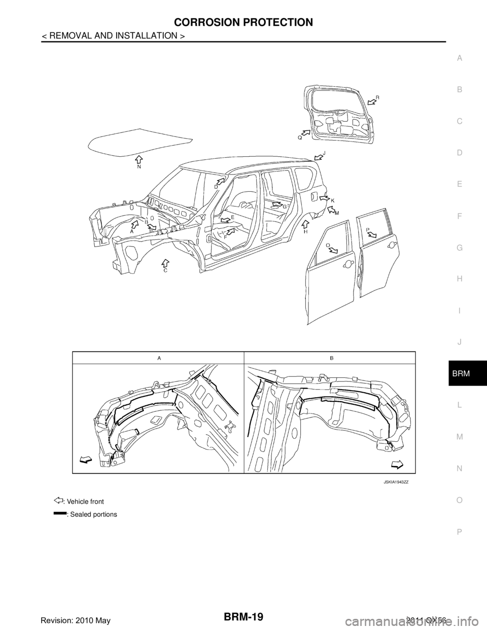
The following figure shows the areas that are sealed at the factory. Sealant that is applied to these areas
should be smooth and free from cuts or gaps. Care s hould be taken not to apply an excess amount of sealant
and not to allow other unaffected parts to come into contact with the sealant.
: Stone guard coated portions
JSKIA1942ZZ
Revision: 2010 May2011 QX56
Page 694 of 5598
CORROSION PROTECTIONBRM-19
< REMOVAL AND INSTALLATION >
C
DE
F
G H
I
J
L
M A
B
BRM
N
O P
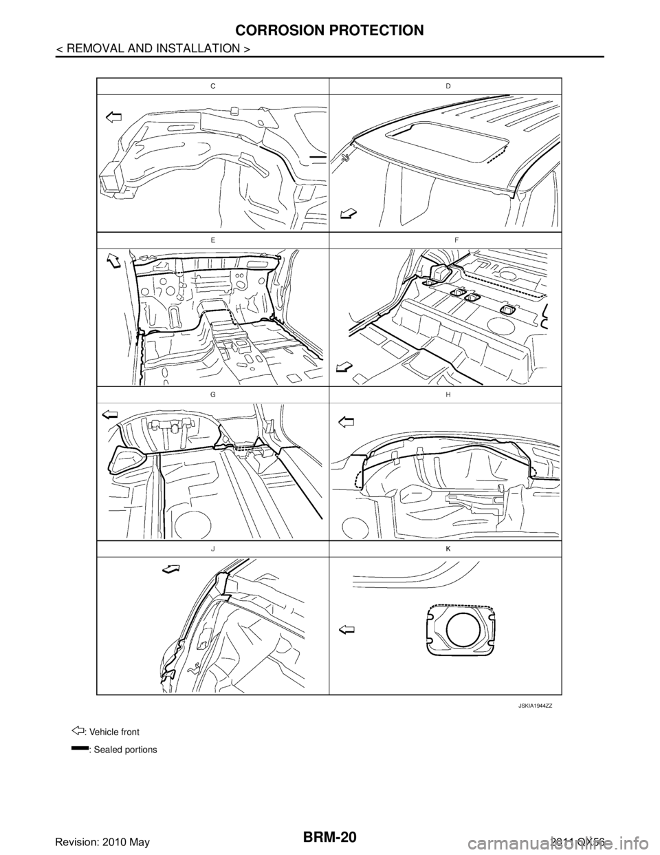
: Vehicle front : Sealed portions
JSKIA1943ZZ
Revision: 2010 May2011 QX56
Page 695 of 5598
BRM-20
< REMOVAL AND INSTALLATION >
CORROSION PROTECTION
: Vehicle front: Sealed portions
JSKIA1944ZZ
Revision: 2010 May2011 QX56
Page 696 of 5598
CORROSION PROTECTIONBRM-21
< REMOVAL AND INSTALLATION >
C
DE
F
G H
I
J
L
M A
B
BRM
N
O P
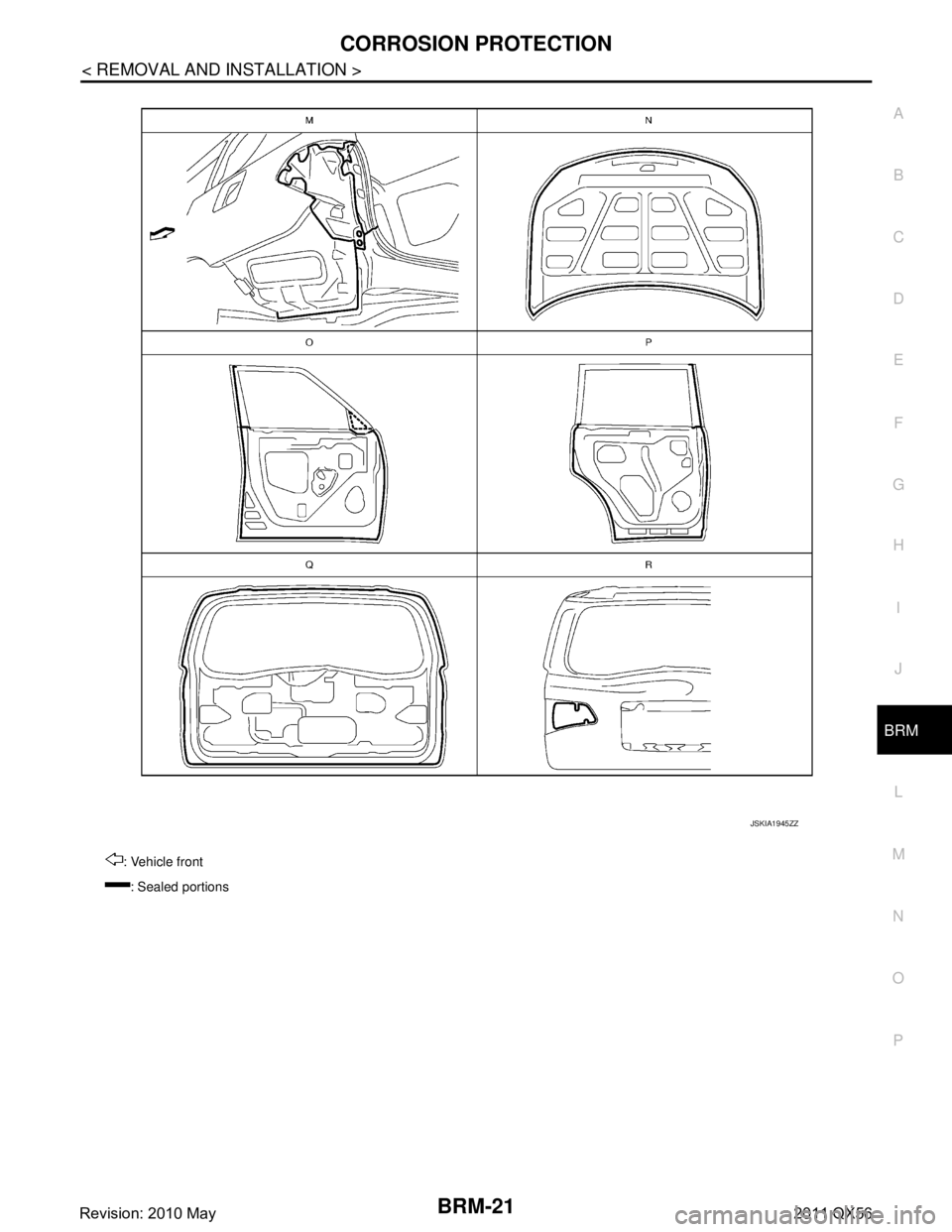
: Vehicle front : Sealed portions
JSKIA1945ZZ
Revision: 2010 May2011 QX56
Page 697 of 5598
BRM-22
< REMOVAL AND INSTALLATION >
BODY CONSTRUCTION
BODY CONSTRUCTION
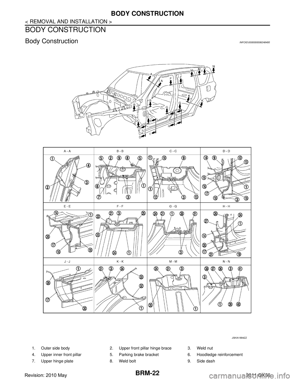
Body ConstructionINFOID:0000000006248495
1. Outer side body 2. Upper front pillar hinge brace 3. Weld nut
4. Upper inner front pillar 5. Parking brake bracket 6. Hoodledge reinforcement
7. Upper hinge plate 8. Weld bolt 9. Side dash
JSKIA1894ZZ
Revision: 2010 May2011 QX56
Page 698 of 5598
BODY CONSTRUCTIONBRM-23
< REMOVAL AND INSTALLATION >
C
DE
F
G H
I
J
L
M A
B
BRM
N
O P
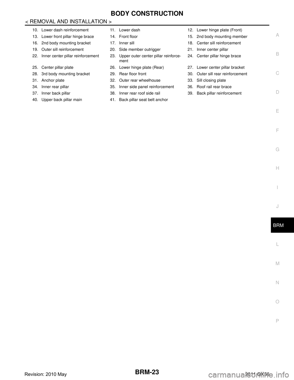
10. Lower dash reinforcement 11. Lower dash 12. Lower hinge plate (Front)
13. Lower front pillar hinge brace 14. Front floor 15. 2nd body mounting member
16. 2nd body mounting bracket 17. Inner sill 18. Center sill reinforcement
19. Outer sill reinforcement 20. Side member outrigger 21. Inner center pillar
22. Inner center pillar reinforcement 23. Upper outer center pillar reinforce- ment24. Center pillar hinge brace
25. Center pillar plate 26. Lower hinge plate (Rear) 27. Lower center pillar bracket
28. 3rd body mounting bracket 29. Rear floor front 30. Outer sill rear reinforcement
31. Anchor plate 32. Outer rear wheelhouse 33. Sill closing plate
34. Inner rear pillar 35. Inner side panel reinforcement 36. Roof rail rear brace
37. Inner back pillar 38. Inner rear roof side rail 39. Back pillar reinforcement
40. Upper back pillar main 41. Back pillar seat belt anchor
Revision: 2010 May2011 QX56
Page 699 of 5598
BRM-24
< REMOVAL AND INSTALLATION >
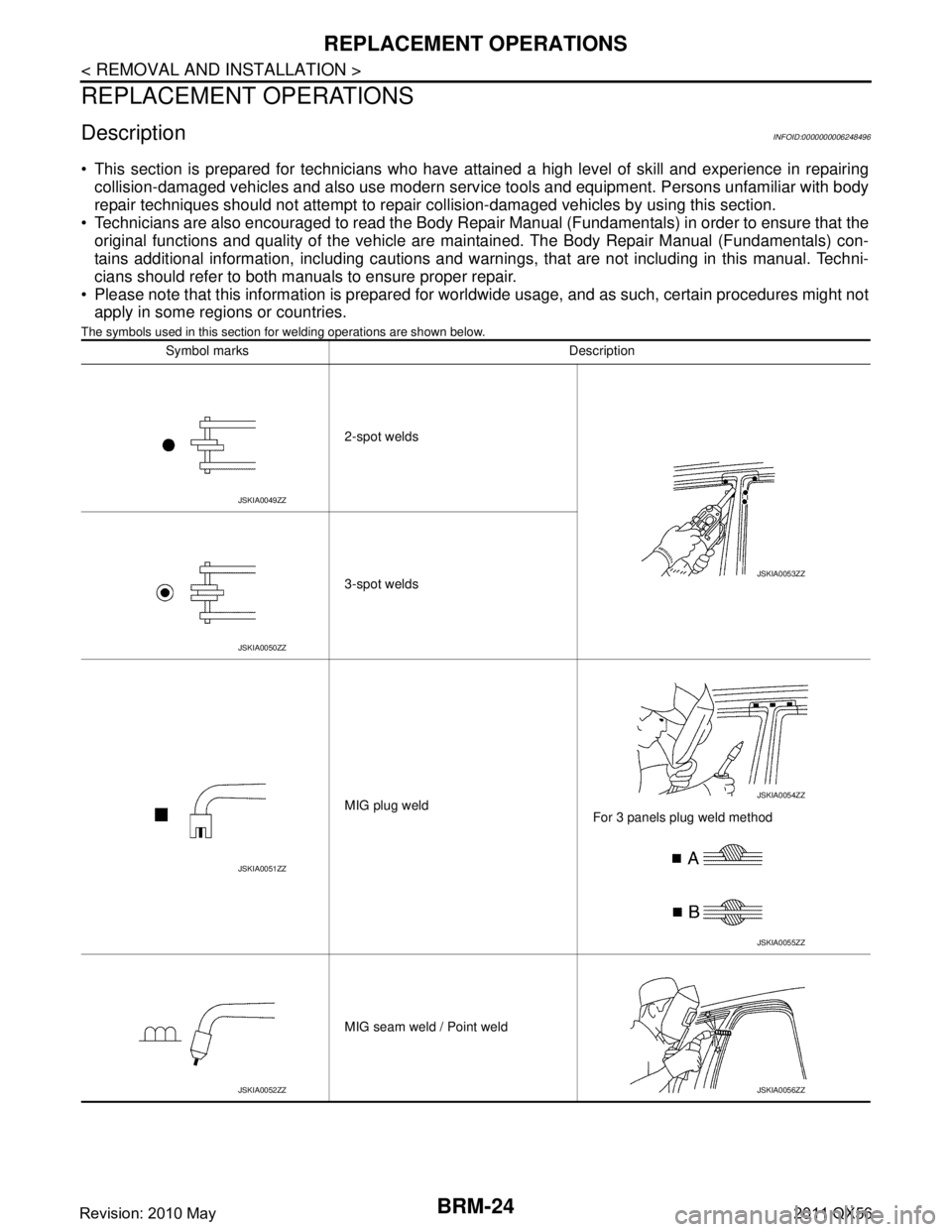
REPLACEMENT OPERATIONS
REPLACEMENT OPERATIONS
DescriptionINFOID:0000000006248496
This section is prepared for technicians who have attained a high level of skill and experience in repairingcollision-damaged vehicles and also use modern serv ice tools and equipment. Persons unfamiliar with body
repair techniques should not attempt to repair collision-damaged vehicles by using this section.
Technicians are also encouraged to read the Body Repair Manual (Fundamentals) in order to ensure that the
original functions and quality of the vehicle are ma intained. The Body Repair Manual (Fundamentals) con-
tains additional information, including cautions and warnings, that are not including in this manual. Techni-
cians should refer to both manuals to ensure proper repair.
Please note that this information is prepared for worldwide usage, and as such, certain procedures might not apply in some regions or countries.
The symbols used in this section fo r welding operations are shown below.
Symbol marks Description
2-spot welds
3-spot welds
MIG plug weld For 3 panels plug weld method
MIG seam weld / Point weld
JSKIA0049ZZ
JSKIA0053ZZ
JSKIA0050ZZ
JSKIA0051ZZ
JSKIA0054ZZ
JSKIA0055ZZ
JSKIA0052ZZJSKIA0056ZZ
Revision: 2010 May2011 QX56
Page 700 of 5598

REPLACEMENT OPERATIONSBRM-25
< REMOVAL AND INSTALLATION >
C
DE
F
G H
I
J
L
M A
B
BRM
N
O P
Front pillar butt joint can be determined anywhere within shaded area as shown in the figure. The best location for the butt joint is at
position A due to the construction of the vehicle.
Determine cutting position and record distance from the locating indent. Use this distance when cutting the service part. Cut outer
front pillar over 60 mm (2.36 in) above the inner front pillar cut
position.
Prepare a cutting jig to make outer pillar easier to cut. Also, this will permit the service part to be accurately cut at the joint position.
An example of cutting operation using a cutting jig is as per the fol- lowing.
1. Mark cutting lines.
A: Cut position of outer pillar
B: Cut position of inner pillar
2. Align cutting line with notch on jig. Clamp jig to pillar.
3. Cut outer pillar along groove of jig (at position A).
4. Remove jig and cut remaining portions.
5. Cut inner pillar at position B in same manner.
PIIA0150E
JSKIA0104GB
JSKIA0105GB
PIIA0153E
Revision: 2010 May2011 QX56
Trending: service reset, jump start terminals, key fob battery, language, service indicator, auxiliary battery, fuel type
