turn signal INFINITI QX56 2011 Factory Manual Online
[x] Cancel search | Manufacturer: INFINITI, Model Year: 2011, Model line: QX56, Model: INFINITI QX56 2011Pages: 5598, PDF Size: 94.53 MB
Page 338 of 5598
AV-190
< DTC/CIRCUIT DIAGNOSIS >
SIDE CAMERA RH COMMUNICATION SIGNAL CIRCUIT
SIDE CAMERA RH COMMUNICATION SIGNAL CIRCUIT
DescriptionINFOID:0000000006216362
Around view monitor control unit supplies to the front camera, rear camera and side came\
ra. And then it
superimpose the images from each camera and outputs then to the front display unit.
Superimpose the guiding lines, predictive course line and sonar indicator to the camera image that outputs
to the front display unit.
Around view monitor control unit performs the rec eption/transmission of communication signal with each
camera.
Diagnosis ProcedureINFOID:0000000006216363
1.CHECK CONTINUITY COMMUNI CATION SIGNAL CIRCUIT
1. Turn ignition switch OFF.
2. Disconnect around view monitor control unit c onnector and door mirror (passenger side) connector.
3. Check continuity between around view monitor c ontrol unit harness connector and door mirror (passenger
side) harness connector.
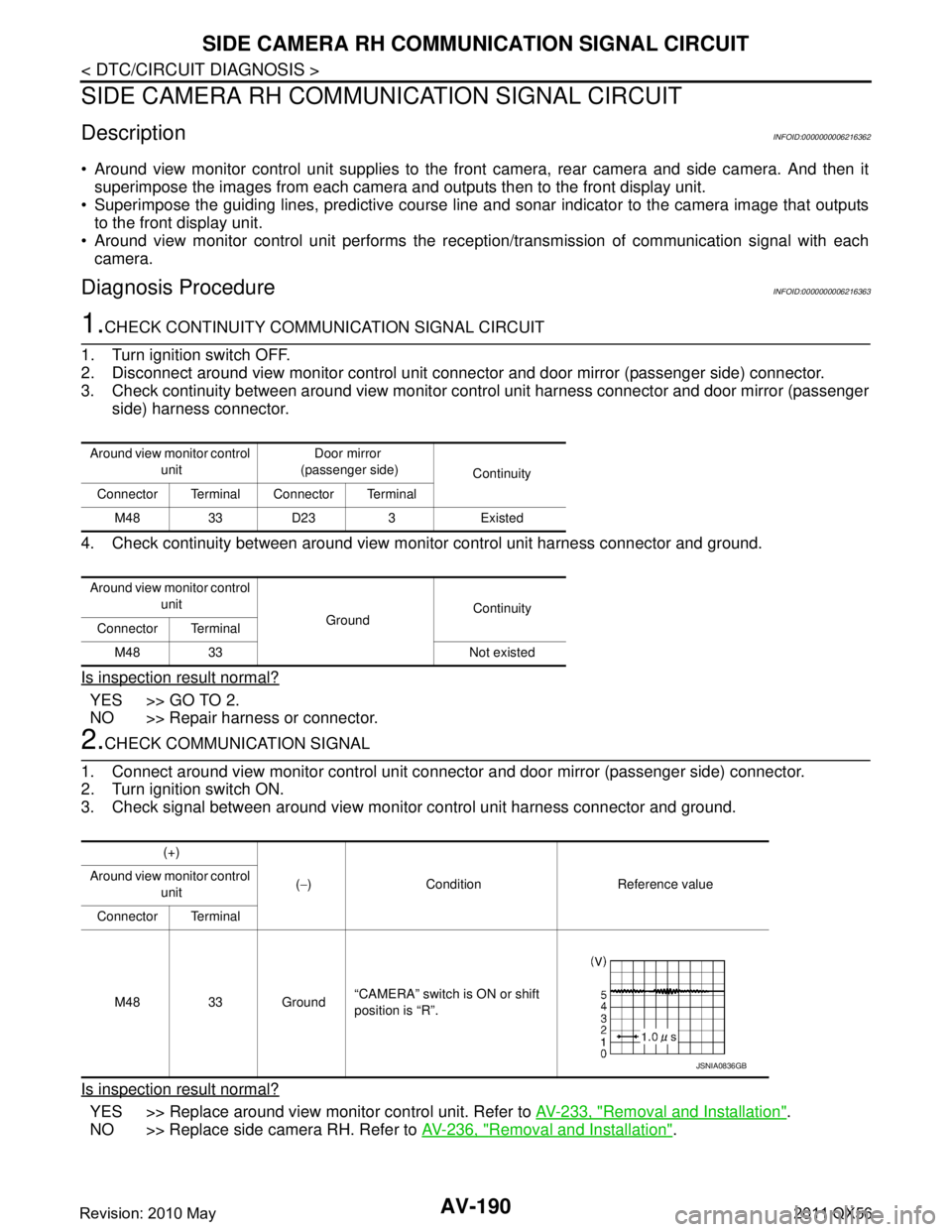
4. Check continuity between around view m onitor control unit harness connector and ground.
Is inspection result normal?
YES >> GO TO 2.
NO >> Repair harness or connector.
2.CHECK COMMUNICATION SIGNAL
1. Connect around view monitor control unit connector and door mirror (passenger side) connector.
2. Turn ignition switch ON.
3. Check signal between around view monitor control unit harness connector and ground.
Is inspection result normal?
YES >> Replace around view monitor control unit. Refer to AV-233, "Removal and Installation".
NO >> Replace side camera RH. Refer to AV-236, "
Removal and Installation".
Around view monitor control
unit Door mirror
(passenger side) Continuity
Connector Terminal Connector Terminal
M48 33 D23 3 Existed
Around view monitor control unit GroundContinuity
Connector Terminal
M48 33 Not existed
(+)
(− ) Condition Reference value
Around view monitor control
unit
Connector Terminal
M48 33 Ground “CAMERA” switch is ON or shift
position is “R”.
JSNIA0836GB
Revision: 2010 May2011 QX56
Page 339 of 5598
AV
SIDE CAMERA RH IMAGE SIGNAL CIRCUITAV-191
< DTC/CIRCUIT DIAGNOSIS >
C
DE
F
G H
I
J
K L
M B A
O P
SIDE CAMERA RH IM AGE SIGNAL CIRCUIT
DescriptionINFOID:0000000006216364
Around view monitor control unit supplies to the front camera, rear camera and side camera. And then it
superimpose the images from each camera and outputs then to the front display unit.
Superimpose the guiding lines, predictive course line and sonar indicator to the camera image that outputs
to the front display unit.
Around view monitor control unit performs the rec eption/transmission of communication signal with each
camera.
Diagnosis ProcedureINFOID:0000000006216365
1.CHECK CONTINUITY SIDE CAMERA RH POWER SUPPLY AND GROUND CIRCUIT
1. Turn ignition switch OFF.
2. Disconnect control unit connector and door mirror (passenger side) connector.
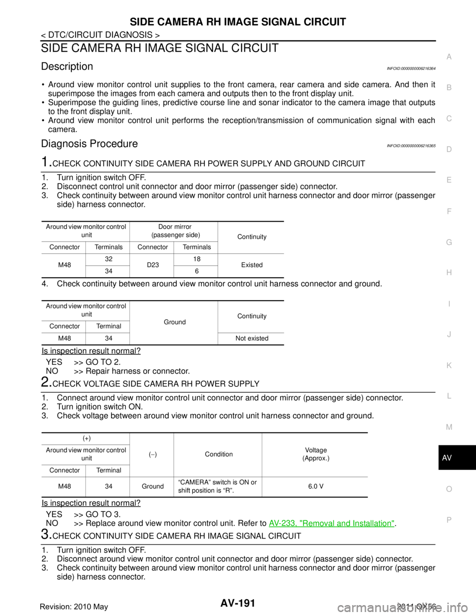
3. Check continuity between around view monitor c ontrol unit harness connector and door mirror (passenger
side) harness connector.
4. Check continuity between around view monitor control unit harness connector and ground.
Is inspection result normal?
YES >> GO TO 2.
NO >> Repair harness or connector.
2.CHECK VOLTAGE SIDE CAMERA RH POWER SUPPLY
1. Connect around view monitor control unit connec tor and door mirror (passenger side) connector.
2. Turn ignition switch ON.
3. Check voltage between around view monitor control unit harness connector and ground.
Is inspection result normal?
YES >> GO TO 3.
NO >> Replace around view monitor control unit. Refer to AV-233, "
Removal and Installation".
3.CHECK CONTINUITY SIDE CAMERA RH IMAGE SIGNAL CIRCUIT
1. Turn ignition switch OFF.
2. Disconnect around view monitor control unit connec tor and door mirror (passenger side) connector.
3. Check continuity between around view monitor c ontrol unit harness connector and door mirror (passenger
side) harness connector.
Around view monitor control
unit Door mirror
(passenger side) Continuity
Connector Terminals Connector Terminals
M48 32
D23 18
Existed
34 6
Around view monitor control unit GroundContinuity
Connector Terminal
M48 34 Not existed
(+)
(− ) Condition Vo l ta g e
(Approx.)
Around view monitor control
unit
Connector Terminal
M48 34 Ground “CAMERA” switch is ON or
shift position is “R”.
6.0 V
Revision: 2010 May2011 QX56
Page 340 of 5598
AV-192
< DTC/CIRCUIT DIAGNOSIS >
SIDE CAMERA RH IMAGE SIGNAL CIRCUIT
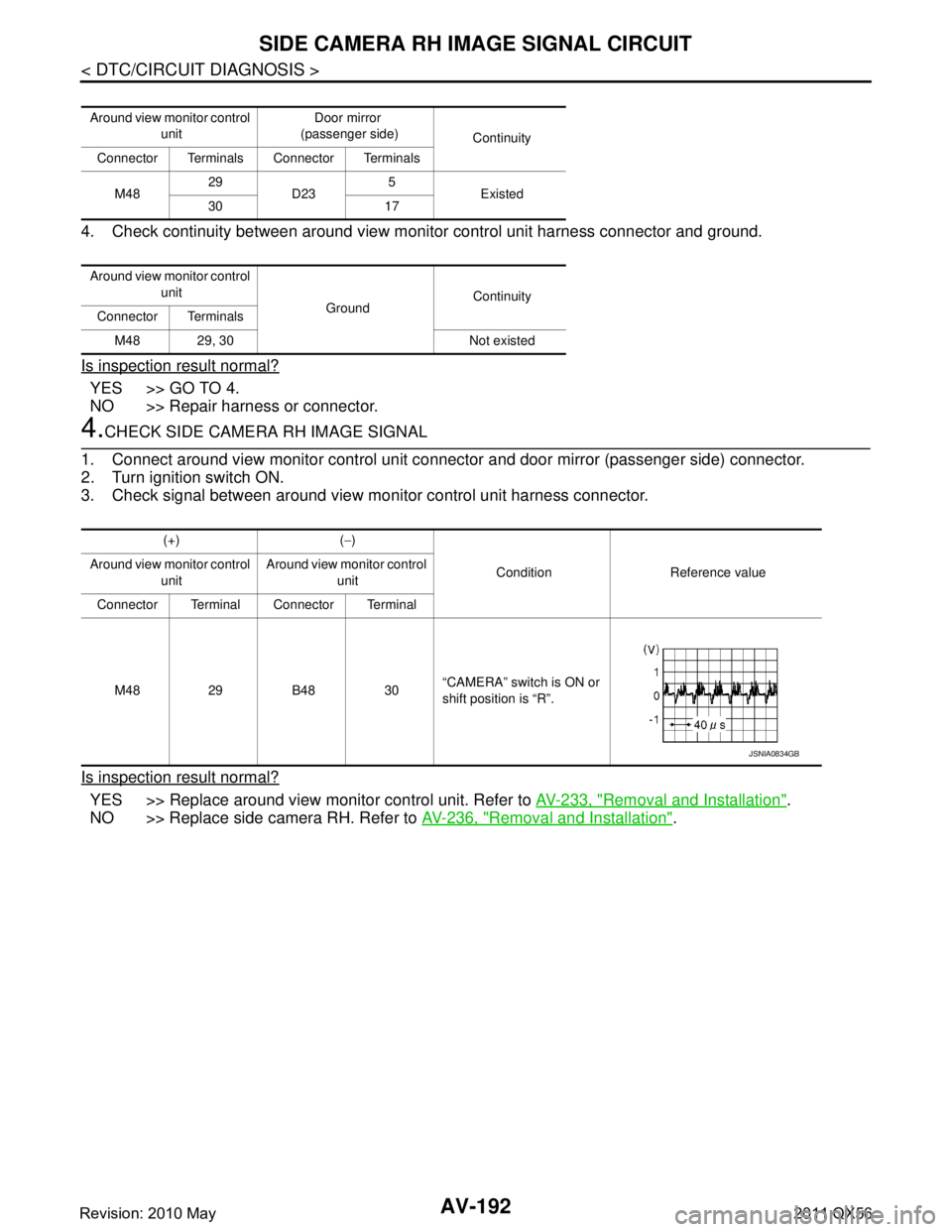
4. Check continuity between around view monitor control unit harness connector and ground.
Is inspection result normal?
YES >> GO TO 4.
NO >> Repair harness or connector.
4.CHECK SIDE CAMERA RH IMAGE SIGNAL
1. Connect around view monitor control unit connector and door mirror (passenger side) connector.
2. Turn ignition switch ON.
3. Check signal between around view monitor control unit harness connector.
Is inspection result normal?
YES >> Replace around view monitor control unit. Refer to AV-233, "Removal and Installation".
NO >> Replace side camera RH. Refer to AV-236, "
Removal and Installation".
Around view monitor control
unit Door mirror
(passenger side) Continuity
Connector Terminals Connector Terminals
M48 29
D23 5
Existed
30 17
Around view monitor control unit GroundContinuity
Connector Terminals
M48 29, 30 Not existed
(+) ( −)
Condition Reference value
Around view monitor control
unit Around view monitor control
unit
Connector Terminal Connector Terminal
M48 29 B48 30 “CAMERA” switch is ON or
shift position is “R”.
JSNIA0834GB
Revision: 2010 May2011 QX56
Page 341 of 5598
AV
STEERING SWITCH SIGNAL A CIRCUITAV-193
< DTC/CIRCUIT DIAGNOSIS >
C
DE
F
G H
I
J
K L
M B A
O P
STEERING SWITCH SI GNAL A CIRCUIT
DescriptionINFOID:0000000006216366
Transmits the steering switch signal to AV control unit.
Diagnosis ProcedureINFOID:0000000006216367
1.CHECK STEERING SWITCH SIGNAL A CIRCUIT
1. Disconnect AV control unit connector and spiral cable connector.
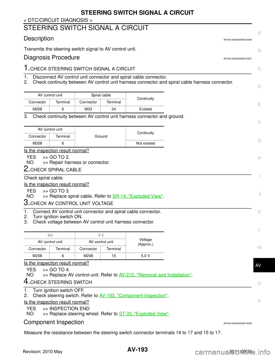
2. Check continuity between AV control unit harness connector and spiral cable harness connector.
3. Check continuity between AV control unit harness connector and ground.
Is the inspection result normal?
YES >> GO TO 2.
NO >> Repair harness or connector.
2.CHECK SPIRAL CABLE
Check spiral cable.
Is the inspection result normal?
YES >> GO TO 3.
NO >> Replace spiral cable. Refer to SR-14, "
Exploded View".
3.CHECK AV CONTROL UNIT VOLTAGE
1. Connect AV control unit connector and spiral cable connector.
2. Turn ignition switch ON.
3. Check voltage between AV control unit harness connector.
Is the inspection result normal?
YES >> GO TO 4.
NO >> Replace AV control unit. Refer to AV-212, "
Removal and Installation".
4.CHECK STEERING SWITCH
1. Turn ignition switch OFF.
2. Check steering switch. Refer to AV-193, "
Component Inspection".
Is the inspection result normal?
YES >> INSPECTION END
NO >> Replace steering wheel. Refer to ST-33, "
Exploded View".
Component InspectionINFOID:0000000006216368
Measure the resistance between the steering s witch connector terminals 14 to 17 and 15 to 17.
AV control unit Spiral cable
Continuity
Connector Terminal Connector Terminal
M208 6 M33 24 Existed
AV control unit GroundContinuity
Connector Terminal
M208 6 Not existed
(+) ( −)
Vo l ta g e
(Approx.)
AV control unit AV control unit
Connector Terminal Connector Terminal M208 6 M208 15 5.0 V
Revision: 2010 May2011 QX56
Page 343 of 5598
AV
STEERING SWITCH SIGNAL B CIRCUITAV-195
< DTC/CIRCUIT DIAGNOSIS >
C
DE
F
G H
I
J
K L
M B A
O P
STEERING SWITCH SI GNAL B CIRCUIT
DescriptionINFOID:0000000006216369
Transmits the steering switch signal to AV control unit.
Diagnosis ProcedureINFOID:0000000006216370
1.CHECK STEERING SWITCH SIGNAL B CIRCUIT
1. Disconnect AV control unit connector and spiral cable connector.
2. Check continuity between AV control unit harness connector and spiral cable harness connector.
3. Check continuity between AV control unit harness connector and ground.
Is the inspection result normal?
YES >> GO TO 2.
NO >> Repair harness or connector.
2.CHECK SPIRAL CABLE
Check spiral cable.
Is the inspection result normal?
YES >> GO TO 3.
NO >> Replace spiral cable. Refer to SR-14, "
Exploded View".
3.CHECK AV CONTROL UNIT VOLTAGE
1. Connect AV control unit connector and spiral cable connector.
2. Turn ignition switch ON.
3. Check voltage between AV control unit harness connector.
Is the inspection result normal?
YES >> GO TO 4.
NO >> Replace AV control unit. Refer to AV-212, "
Removal and Installation".
4.CHECK STEERING SWITCH
1. Turn ignition switch OFF.
2. Check steering switch. Refer to AV-195, "
Component Inspection".
Is the inspection result normal?
YES >> INSPECTION END
NO >> Replace steering wheel. Refer to ST-33, "
Exploded View".
Component InspectionINFOID:0000000006216371
Measure the resistance between the steering s witch connector terminals 14 to 17 and 15 to 17.
AV control unit Spiral cable
Continuity
Connector Terminal Connector Terminal
M208 16 M33 31 Existed
AV control unit GroundContinuity
Connector Terminal
M208 16 Not existed
(+) ( −)
Vo l ta g e
(Approx.)
AV control unit AV control unit
Connector Terminal Connector Terminal M208 16 M208 15 5.0 V
Revision: 2010 May2011 QX56
Page 345 of 5598
AV
STEERING SWITCH GROUND CIRCUITAV-197
< DTC/CIRCUIT DIAGNOSIS >
C
DE
F
G H
I
J
K L
M B A
O P
STEERING SWITCH GROUND CIRCUIT
DescriptionINFOID:0000000006216372
Transmits the steering switch signal to AV control unit.
Diagnosis ProcedureINFOID:0000000006216373
1.CHECK STEERING SWITCH SIGNAL GROUND CIRCUIT
1. Disconnect AV control unit connector and spiral cable connector.
2. Check continuity between AV control unit harness connector and spiral cable harness connector.
3. Connect AV control unit connector.
Is the inspection result normal?
YES >> GO TO 2.
NO >> Repair harness or connector.
2.CHECK SPIRAL CABLE
Check spiral cable.
Is the inspection result normal?
YES >> GO TO 3.
NO >> Replace spiral cable. Refer to SR-14, "
Exploded View".
3.CHECK GROUND CIRCUIT
1. Connect AV control unit connector.
2. Check continuity between AV control unit harness connector and ground.
Is the inspection result normal?
YES >> GO TO 4.
NO >> Replace AV control unit. Refer to AV-212, "
Removal and Installation".
4.CHECK STEERING SWITCH
1. Turn ignition switch OFF.
2. Check steering switch. Refer to AV-197, "
Component Inspection".
Is the inspection result normal?
YES >> INSPECTION END
NO >> Replace steering wheel. Refer to ST-33, "
Exploded View".
Component InspectionINFOID:0000000006216374
Measure the resistance between the steering s witch connector terminals 14 to 17 and 15 to 17.
AV control unit Spiral cable
Continuity
Connector Terminal Connector Terminal
M208 15 M33 33 Existed
AV control unit GroundContinuity
Connector Terminal
M208 15 Existed
Revision: 2010 May2011 QX56
Page 347 of 5598
AV
MULTI AV SYSTEM SYMPTOMSAV-199
< SYMPTOM DIAGNOSIS >
C
DE
F
G H
I
J
K L
M B A
O P
SYMPTOM DIAGNOSIS
MULTI AV SYSTEM SYMPTOMS
Symptom TableINFOID:0000000006216375
RELATED TO NAVIGATION
RELATED TO HANDS-FREE PHONE
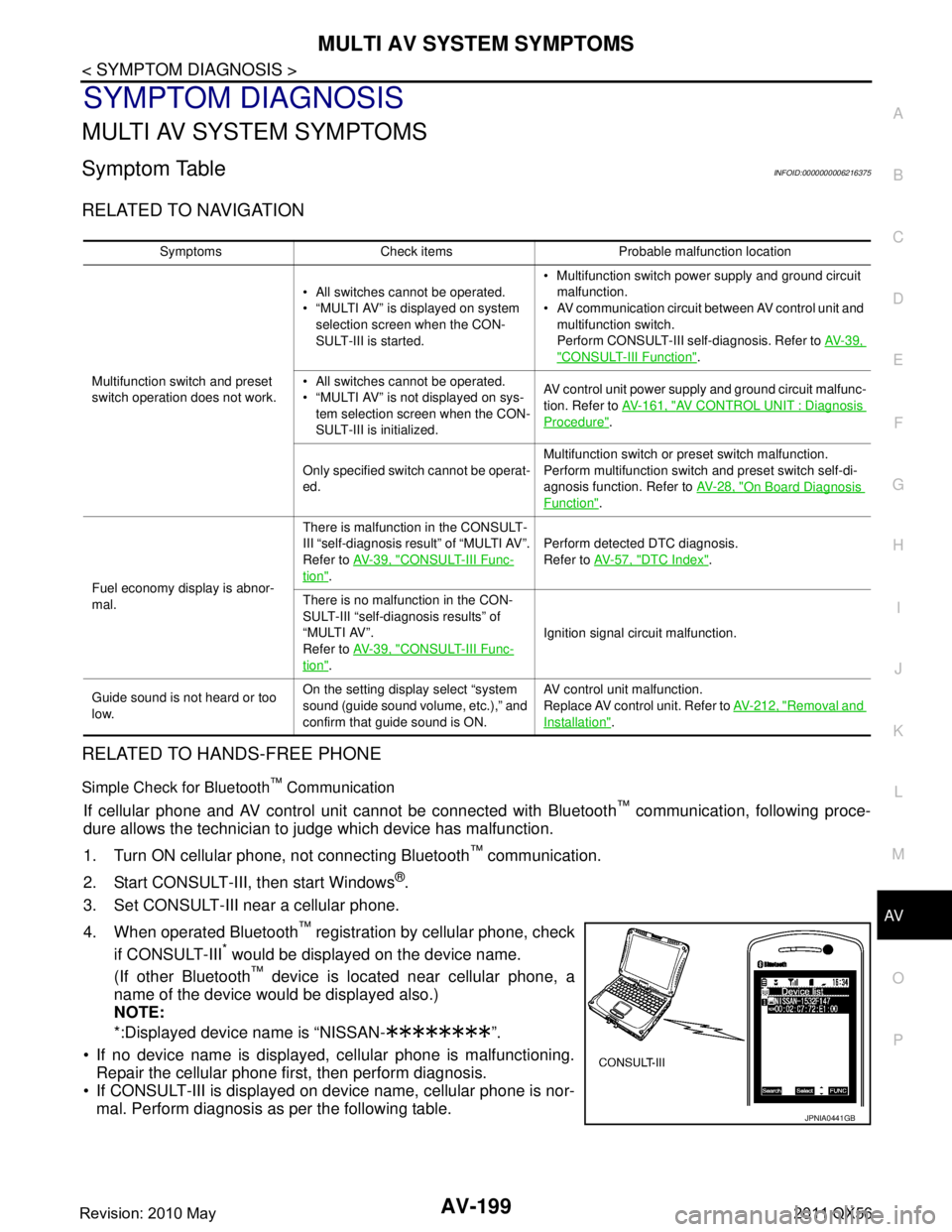
Simple Check for Bluetooth™ Communication
If cellular phone and AV control unit cannot be connected with Bluetooth™ communication, following proce-
dure allows the technician to judge which device has malfunction.
1. Turn ON cellular phone, not connecting Bluetooth
™ communication.
2. Start CONSULT-III, then start Windows
®.
3. Set CONSULT-III near a cellular phone.
4. When operated Bluetooth
™ registration by cellular phone, check
if CONSULT-III
* would be displayed on the device name.
(If other Bluetooth
™ device is located near cellular phone, a
name of the device would be displayed also.)
NOTE:
*:Displayed device name is “NISSAN- ”.
If no device name is displayed, cellular phone is malfunctioning. Repair the cellular phone first, then perform diagnosis.
If CONSULT-III is displayed on device name, cellular phone is nor- mal. Perform diagnosis as per the following table.
Symptoms Check items Probable malfunction location
Multifunction switch and preset
switch operation does not work. All switches cannot be operated.
“MULTI AV” is displayed on system
selection screen when the CON-
SULT-III is started. Multifunction switch power supply and ground circuit
malfunction.
AV communication circuit between AV control unit and
multifunction switch.
Perform CONSULT-III self-diagnosis. Refer to AV- 3 9 ,
"CONSULT-III Function".
All switches cannot be operated.
“MULTI AV” is not displayed on sys- tem selection screen when the CON-
SULT-III is initialized. AV control unit power supply and ground circuit malfunc-
tion. Refer to
AV- 1 6 1 , "
AV CONTROL UNIT : Diagnosis
Procedure".
Only specified switch cannot be operat-
ed. Multifunction switch or preset switch malfunction.
Perform multifunction switch and preset switch self-di-
agnosis function. Refer to
AV- 2 8 , "
On Board Diagnosis
Function".
Fuel economy display is abnor-
mal. There is malfunction in the CONSULT-
III “self-diagnosis result” of “MULTI AV”.
Refer to
AV- 3 9 , "
CONSULT-III Func-
tion". Perform detected DTC diagnosis.
Refer to
AV- 5 7 , "
DTC Index".
There is no malfunction in the CON-
SULT-III “self-diagnosis results” of
“MULTI AV”.
Refer to AV- 3 9 , "
CONSULT-III Func-
tion". Ignition signal circuit malfunction.
Guide sound is not heard or too
low. On the setting display select “system
sound (guide sound volume, etc.),” and
confirm that guide sound is ON. AV control unit malfunction.
Replace AV control unit. Refer to
AV- 2 1 2 , "
Removal and
Installation".
JPNIA0441GB
Revision: 2010 May2011 QX56
Page 349 of 5598
AV
MULTI AV SYSTEM SYMPTOMSAV-201
< SYMPTOM DIAGNOSIS >
C
DE
F
G H
I
J
K L
M B A
O P
RELATED TO CAMERA ASSISTANCE SONAR
The predicted course line display in
front view and rear view is malfunc-
tioning. The “Steer. Angle Sensor” is not turned ON at “Con-
nection Confirmation” of “Camera Cont.”
Steering angle sensor signal circuits.
The front view screen is not dis- played.
The front of Birds-Eye view
screen is not displayed. Check the item Front
Camera in “Connec-
tion Confirmation”
mode of “Camera
Cont.” Image Output Signal: NG
COMM Status: NG
COMM Line: NG
Front camera image signal circuit
malfunction.
Front camera po wer supply and
ground circuits malfunction.
Refer to AV- 1 8 2 , "
Diagnosis Proce-
dure".
Image Output Signal: OK
COMM Status: NG
COMM Line: NG Front camera communication signal cir-
cuit malfunction. Refer to
AV-181, "
Di-
agnosis Procedure".
The rear view screen is not dis- played.
The rear of Birds-Eye view screen is not displayed. Check the item Rear
Camera in “Connec-
tion Confirmation”
mode of “Camera
Cont.” Image Output Signal: NG
COMM Status: NG
COMM Line: NG
Rear camera image signal circuit
malfunction.
Rear camera po wer supply and
ground circuits malfunction.
Refer to AV- 1 8 5 , "
Diagnosis Proce-
dure".
Image Output Signal: OK
COMM Status: NG
COMM Line: NG Rear camera communication signal cir-
cuits malfunction. Refer to
AV- 1 8 4 , "
Di-
agnosis Procedure".
The front-side screen is not dis- played.
The passenger side of Birds-Eye view screen is not displayed. Check the item Pass-
Side Camera in “Con-
nection Confirmation”
mode of “Camera
Cont.” Image Output Signal: NG
COMM Status: NG
COMM Line: NG
Side camera RH image signal circuit
malfunction.
Side camera RH power supply and
ground circuits malfunction.
Refer to AV- 1 9 1 , "
Diagnosis Proce-
dure".
Image Output Signal: OK
COMM Status: NG
COMM Line: NG Side camera RH communication cir-
cuit malfunction. Refer to AV- 1 9 0 ,
"Diagnosis Procedure".
The driver side of Birds-eye view
screen is not displayed. Check the item Dr-
Side Camera at “Con-
nection Confirmation”
mode of “Camera
Cont.” Image Output Signal: NG
COMM Status: NG
COMM Line: NG
Side camera LH image signal circuit
malfunction.
Side camera LH power supply and ground circuits malfunction.
Refer to AV- 1 8 8 , "
Diagnosis Proce-
dure".
Image Output Signal: OK
COMM Status: NG
COMM Line: NG Side camera LH communication cir-
cuit malfunction. Refer to AV- 1 8 7 ,
"Diagnosis Procedure".
When shift position is other than “R”
the front-side and front screen or the
Birds-Eye view and front screen re-
main displaying even if the vehicle
speed increases. —
Vehicle speed signal circuit malfunction
(around view moni
tor control unit).
Symptoms Check items
Probable malfunction location / Action
to take
Revision: 2010 May2011 QX56
Page 356 of 5598

AV-208
< SYMPTOM DIAGNOSIS >
NORMAL OPERATING CONDITION
RELATED TO AUDIO
The majority of the audio malfunctions are the result of outside causes (bad CD, electromagnetic interfer-
ence, etc.). Check the symptoms below to diagnose the malfunction.
The vehicle itself can be a source of noise if noise prevention parts or electrical equipment is malfunctioning.
Check if noise is caused and/or changed by engine speed, ignition switch turned to each position, and oper-
ation of each piece of electrical equipment, and then determine the cause.
NOTE:
CD-R is not guaranteed to play because they can c ontain compressed audio (MP3, WMA, AAC, M4A) or
could be incorrectly mastered by the customer on a computer.
Check if the CDs carry the Compact Disc Logo. If not, the disc is not mastered to the “red book” Compact
Disc Standard and may not play.
Noise resulting from variations in field strength, such as fading noise and multi-path noise, or external noise from trains and other
sources, is not a malfunction.
NOTE:
Fading noise: This noise occurs because of variations in the field strength in a narrow range due to mountains or buildings bl ocking
the signal.
Multi-path noise: This noise results from a time difference between the broadcast waves directly from the station arriving at the
antenna and the waves reflected by mountains or buildings.
RELATED TO DVD
The system consistently selects
the wrong voicetag 1. Ensure that the phone book entry name requested matches what was originally stored. This
can be confirmed by using the “List Names” command.
2. Replace one of the names being confused with a new name.
Symptom Solution
Symptom Cause and Counter measure
Cannot play Check if the CD was
inserted correctly.
Check if the CD is scratched or dirty.
Check if there is condensation inside the player, and if there is, wait until the condensation is gone
(about 1 hour) before using the player.
If there is a temperature increase error, the player will play correctly after it returns to the normal
temperature.
If there is a mixture of music CD files (CD-DA data) and MP3/WMA/AAC/M4A files on a CD, only
the music CD files (CD-DA data) will be played.
Files with extensions other than “.MP3”, “.WMA”, “AAC”, “.M4A”, “.mp3”, “.wma”, “.aac” or “.m4a”
cannot be played. In addition, the character codes and number of characters for folder names and
file names should be in compliance with the specifications.
Check if the disc or the file is generated in an irregular format, This may occur depending on the
variation or the setting of MP3/WMA/AAC/M4A writing applications or other text editing applica-
tions.
Check if the finalization process, such as session close and disc close, is done for the disc.
Check if the CD is protected by copyright.
Disks recorded in live file system format are not supported. (For Microsoft Windows Vista, check
the settings.)
Poor sound quality Check if the CD is scratched or dirty.
It takes a relatively long time before
the music starts playing. If there are many folder or file levels on the MP3/WMA/AAC/M4A CD, or if it is a multisession disc,
some time may be required before the music starts playing.
Music cuts off or skips The writing software and hardware combination might not match, or the writing speed, writing
depth, writing width might not match the specifications. Try using the slowest writing speed.
Skipping with high bit rate files Skipping may occur with large quantities if data such as for high bit rate data.
Move immediately to the next song
when playing When a non-MP3/WMA/AAC/M4A file has been given an extension of “.MP3”, “.WMA”, “AAC”,
“.M4A” “.mp3”, “.wma”, “.aac” or “.m4a”, or when play is prohibited by copyright protection, the
player will skip to the next song.
The songs do not play back in the
desired order. The playback order is the order in which the files were written by the software, so the files might
not play in the desired order.
Revision: 2010 May2011 QX56
Page 358 of 5598

AV-210
< SYMPTOM DIAGNOSIS >
NORMAL OPERATING CONDITION
RELATED TO ROUTE CALCULATION AND VISUAL GUIDANCE
The vehicle icon is not displayed in
the correct position.The vehicle was transported after the ignition
switch was pressed off, for example, by a ferry
or car transporter.
Drive the vehicle for a while on a road where
GPS signals can be received.
The position and direction of the vehicle icon
may be incorrect depending on the driving en-
vironments and the levels of positioning accu-
racy of the navigation system. This is not a malfunction. Drive the vehicle for
a while to automatically correct the position
and direction of the vehicle icon.
When the vehicle is traveling on a
new road, the vehicle icon is located
on another road nearby. Because the new road is not stored in the map
data, the system automatically places the vehi-
cle icon on the nearest road available.
Updated road information will be included in
the next version of the map data.
The screen does not switch to the
night screen even after turning on
the headlights. The daytime screen was set the last time the
headlights were turned on.
Set the screen to the night screen mode using
The map does not scroll even when
the vehicle is moving. The current location map screen is not dis-
played.
Press “MAP”.
The vehicle icon is not displayed. The current location map screen is not dis-
played.
Press “MAP”.
The location of the vehicle icon is
misaligned from the actual position. When using tire chains or replacing the tires,
speed calculations based on the speed sensor
may be incorrect. Drive the vehicle for a while [at approximately
30 km/h (19 MPH) for about 30 minutes] to
automatically correct the vehicle icon posi-
tion.
If this does not correct the vehicle icon posi-
tion, contact an INFINITI dealer.
The map data has a mistake or is incomplete
(the vehicle icon position is always misaligned
in the same area). Updated road information will be included in
the next version of the map data.
Symptom Possible cause Possible solution
Symptom Possible cause Possible solution
Waypoints are not included in
the auto reroute calculation. Waypoints that you have already passed are not included in
the auto reroute calculation. If you want to go to that waypoint
again, you need to edit the route.
Route information is not dis-
played. Route calculation has not yet been performed.
Set the destination and perform route
calculation.
You are not driving on the suggested route. Drive on the suggested route.
Route guidance is set to off. Turn on route guidance.
Route information is not provided for certain types of roads
(roads displayed in gray). This is not a malfunction.
The auto reroute calculation (or
detour calculation) suggests
the same route as the one pre-
viously suggested. Route calculations took priority conditions into consider-
ation, but the same route was calculated.
This is not a malfunction.
A waypoint cannot be added. Five waypoints are already set on the route, including ones
that you have already passed. A maximum of 5 waypoints can be set
on the route. If you want to go to 6 or
more waypoints, perform route calcu-
lations multiple times as necessary.
The suggested route is not dis-
played. Roads near the destination cannot be calculated.
Reset the destination to a main or or-
dinary road, and recalculate the route.
The starting point and destination are too close. Set a more distant destination.
The starting point and destination are too far away. Divide your trip by selecting one or two
intermediate destinations, and per-
form route calculations multiple times.
There are time restricted roads (by the day of the week, by
time) near the current vehicle location or destination. Set [Use Time Restricted Roads] to
off.
Revision: 2010 May2011 QX56