Circuit ISUZU KB P190 2007 Workshop Repair Manual
[x] Cancel search | Manufacturer: ISUZU, Model Year: 2007, Model line: KB P190, Model: ISUZU KB P190 2007Pages: 6020, PDF Size: 70.23 MB
Page 4076 of 6020
7A2-110 TRANSMISSION CONTROL SYSTEM (AW30–40LE)
Conditions For Clearing The DTC
• The DTC can be cleared from the TCM history by
using a scan tool.
• The DTC will be cleared from history when the vehicle has achieved 40 warm-up cycles without a
failure reported.
•
After more than 1 second has elapsed after the
ignition key has been turned “ON”, short between
No.11 and No.4 (ground) of DLC (Data Link
Connector). Then, after 1 second, but within 6
seconds, discontinue shorting.
Diagnostic Aids
• Inspect the wiring for poor electrical connection at the
TCM. Look for possible bent, backed out, deformed
or damaged terminals. Check for weak terminal
tension as well. Also check for a chafed wire that
could short to bare metal or other wiring. Inspect for a
broken wire inside the insulation.
• W hen diagnosing for a possible intermittent short o
r
open condition, move the wiring harness while
observing test equipment for a change.
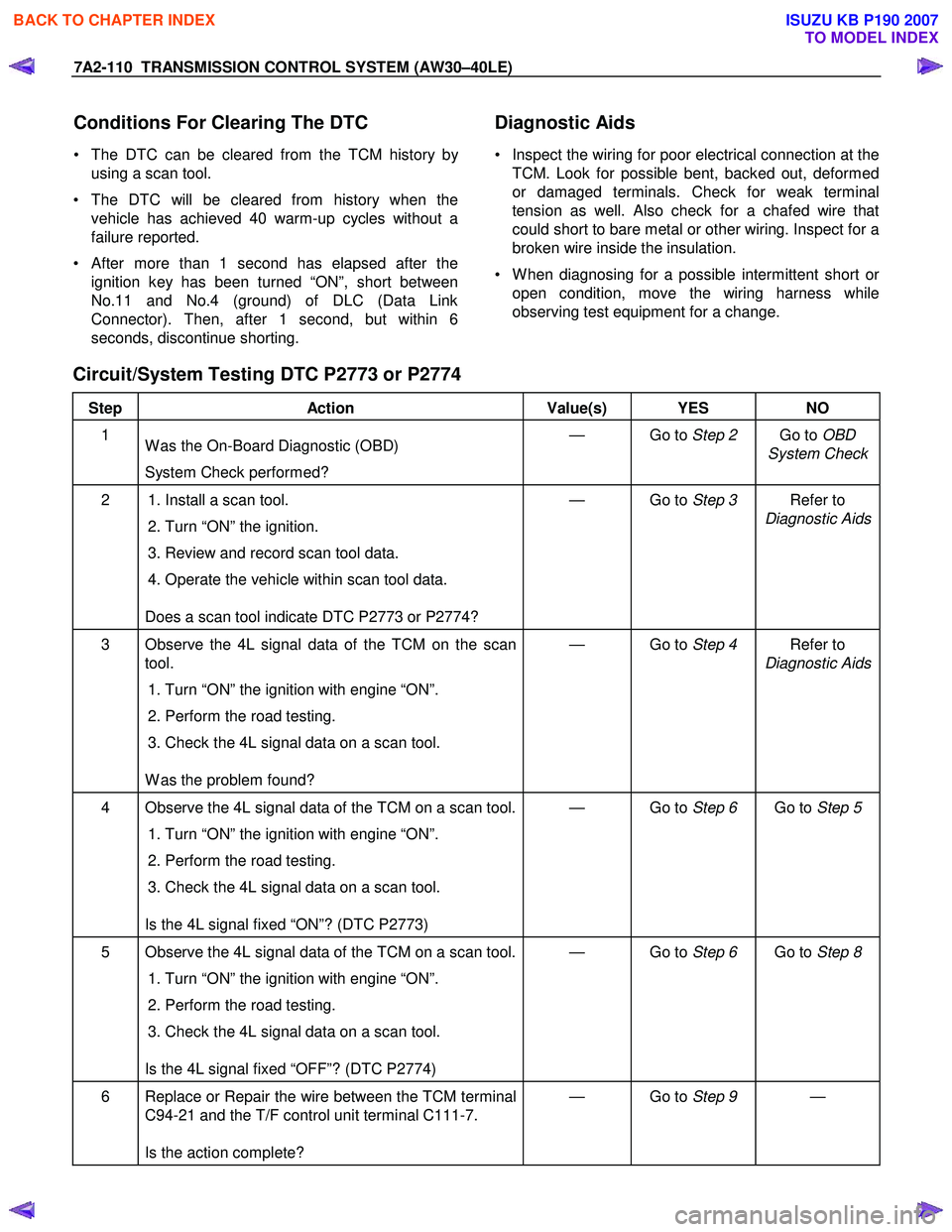
Circuit/System Testing DTC P2773 or P2774
Step Action Value(s) YES NO
1
W as the On-Board Diagnostic (OBD)
System Check performed? — Go to
Step 2 Go to OBD
System Check
2 1. Install a scan tool.
2. Turn “ON” the ignition.
3. Review and record scan tool data.
4. Operate the vehicle within scan tool data.
Does a scan tool indicate DTC P2773 or P2774? — Go to
Step 3 Refer to
Diagnostic Aids
3 Observe the 4L signal data of the TCM on the scan tool.
1. Turn “ON” the ignition with engine “ON”.
2. Perform the road testing.
3. Check the 4L signal data on a scan tool.
W as the problem found? — Go to
Step 4 Refer to
Diagnostic Aids
4 Observe the 4L signal data of the TCM on a scan tool.
1. Turn “ON” the ignition with engine “ON”.
2. Perform the road testing.
3. Check the 4L signal data on a scan tool.
Is the 4L signal fixed “ON”? (DTC P2773) — Go to
Step 6 Go to Step 5
5 Observe the 4L signal data of the TCM on a scan tool.
1. Turn “ON” the ignition with engine “ON”.
2. Perform the road testing.
3. Check the 4L signal data on a scan tool.
Is the 4L signal fixed “OFF”? (DTC P2774) — Go to
Step 6 Go to Step 8
6 Replace or Repair the wire between the TCM terminal
C94-21 and the T/F control unit terminal C111-7.
Is the action complete? — Go to
Step 9 —
BACK TO CHAPTER INDEX
TO MODEL INDEX
ISUZU KB P190 2007
Page 4078 of 6020
7A2-112 TRANSMISSION CONTROL SYSTEM (AW30–40LE)
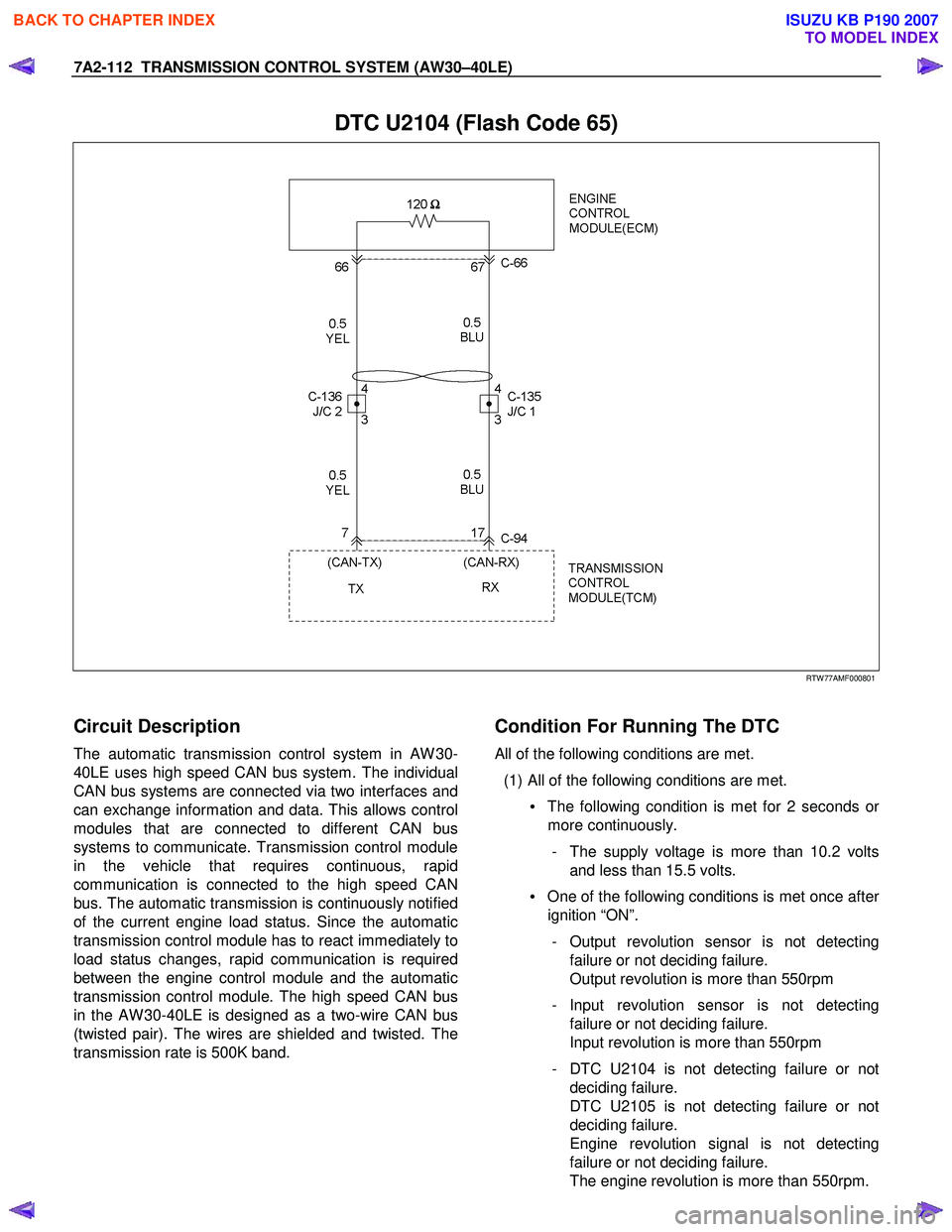
DTC U2104 (Flash Code 65)
RTW 77AMF000801
Circuit Description
The automatic transmission control system in AW 30-
40LE uses high speed CAN bus system. The individual
CAN bus systems are connected via two interfaces and
can exchange information and data. This allows control
modules that are connected to different CAN bus
systems to communicate. Transmission control module
in the vehicle that requires continuous, rapid
communication is connected to the high speed CAN
bus. The automatic transmission is continuously notified
of the current engine load status. Since the automatic
transmission control module has to react immediately to
load status changes, rapid communication is required
between the engine control module and the automatic
transmission control module. The high speed CAN bus
in the AW 30-40LE is designed as a two-wire CAN bus
(twisted pair). The wires are shielded and twisted. The
transmission rate is 500K band.
Condition For Running The DTC
All of the following conditions are met.
(1) All of the following conditions are met. • The following condition is met for 2 seconds o
r
more continuously.
- The supply voltage is more than 10.2 volts and less than 15.5 volts.
• One of the following conditions is met once afte
r
ignition “ON”.
- Output revolution sensor is not detecting failure or not deciding failure.
Output revolution is more than 550rpm
- Input revolution sensor is not detecting failure or not deciding failure.
Input revolution is more than 550rpm
- DTC U2104 is not detecting failure or not deciding failure.
DTC U2105 is not detecting failure or not
deciding failure.
Engine revolution signal is not detecting
failure or not deciding failure.
The engine revolution is more than 550rpm.
BACK TO CHAPTER INDEX
TO MODEL INDEX
ISUZU KB P190 2007
Page 4080 of 6020
7A2-114 TRANSMISSION CONTROL SYSTEM (AW30–40LE)
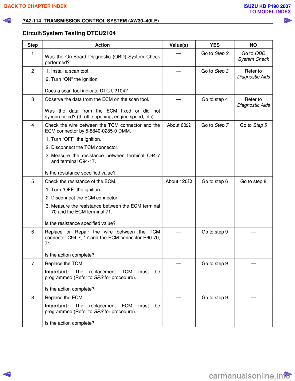
Circuit/System Testing DTCU2104
Step Action Value(s) YES NO
1
W as the On-Board Diagnostic (OBD) System Check
performed? — Go to
Step 2 Go to OBD
System Check
2 1. Install a scan tool.
2. Turn “ON” the ignition.
Does a scan tool indicate DTC U2104? — Go to
Step 3 Refer to
Diagnostic Aids
3 Observe the data from the ECM on the scan tool.
W as the data from the ECM fixed or did not
synchronized? (throttle opening, engine speed, etc) — Go to step 4 Refer to
Diagnostic Aids
4 Check the wire between the TCM connector and the ECM connector by 5-8840-0285-0 DMM.
1. Turn “OFF” the ignition.
2. Disconnect the TCM connector.
3. Measure the resistance between terminal C94-7
and terminal C94-17.
Is the resistance specified value? About 60Ω Go to
Step 7 Go to Step 5
5 Check the resistance of the ECM.
1. Turn “OFF” the ignition.
2. Disconnect the ECM connector.
3. Measure the resistance between the ECM terminal
70 and the ECM terminal 71.
Is the resistance specified value? About 120ΩGo to step 6 Go to step 8
6 Replace or Repair the wire between the TCM
connector C94-7, 17 and the ECM connector E60-70,
71.
Is the action complete? — Go to step 9 —
7 Replace the TCM.
Important: The replacement TCM must be
programmed (Refer to SPS for procedure).
Is the action complete? — Go to step 9 —
8 Replace the ECM.
Important: The replacement ECM must be
programmed (Refer to SPS for procedure).
Is the action complete? — Go to step 9 —
BACK TO CHAPTER INDEX
TO MODEL INDEX
ISUZU KB P190 2007
Page 4082 of 6020
7A2-116 TRANSMISSION CONTROL SYSTEM (AW30–40LE)
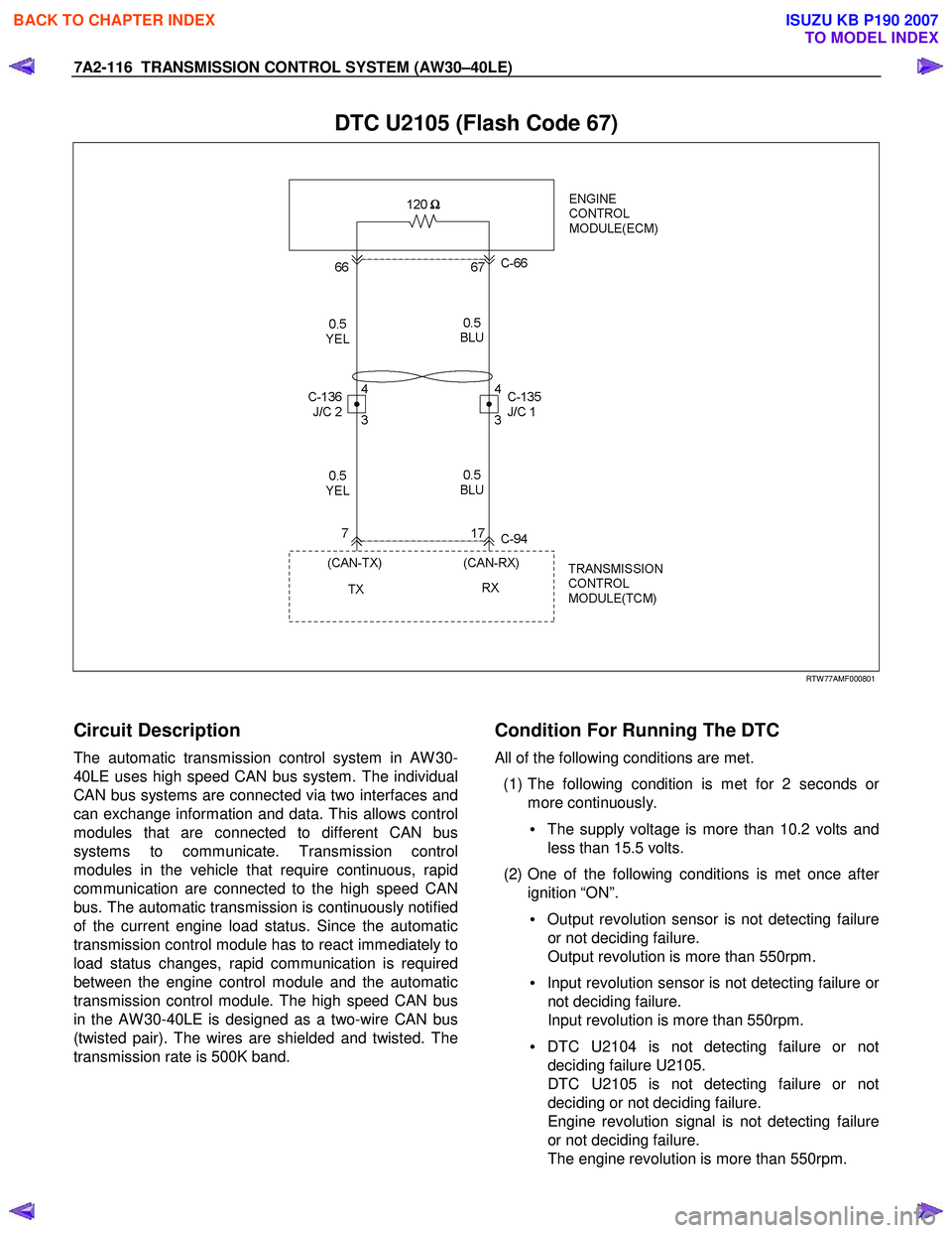
DTC U2105 (Flash Code 67)
RTW 77AMF000801
Circuit Description
The automatic transmission control system in AW 30-
40LE uses high speed CAN bus system. The individual
CAN bus systems are connected via two interfaces and
can exchange information and data. This allows control
modules that are connected to different CAN bus
systems to communicate. Transmission control
modules in the vehicle that require continuous, rapid
communication are connected to the high speed CAN
bus. The automatic transmission is continuously notified
of the current engine load status. Since the automatic
transmission control module has to react immediately to
load status changes, rapid communication is required
between the engine control module and the automatic
transmission control module. The high speed CAN bus
in the AW 30-40LE is designed as a two-wire CAN bus
(twisted pair). The wires are shielded and twisted. The
transmission rate is 500K band.
Condition For Running The DTC
All of the following conditions are met.
(1) The following condition is met for 2 seconds o
r
more continuously.
• The supply voltage is more than 10.2 volts and
less than 15.5 volts.
(2) One of the following conditions is met once afte
r
ignition “ON”.
• Output revolution sensor is not detecting failure
or not deciding failure.
Output revolution is more than 550rpm.
• Input revolution sensor is not detecting failure o
r
not deciding failure.
Input revolution is more than 550rpm.
• DTC U2104 is not detecting failure or not
deciding failure U2105.
DTC U2105 is not detecting failure or not
deciding or not deciding failure.
Engine revolution signal is not detecting failure
or not deciding failure.
The engine revolution is more than 550rpm.
BACK TO CHAPTER INDEX
TO MODEL INDEX
ISUZU KB P190 2007
Page 4084 of 6020
7A2-118 TRANSMISSION CONTROL SYSTEM (AW30–40LE)
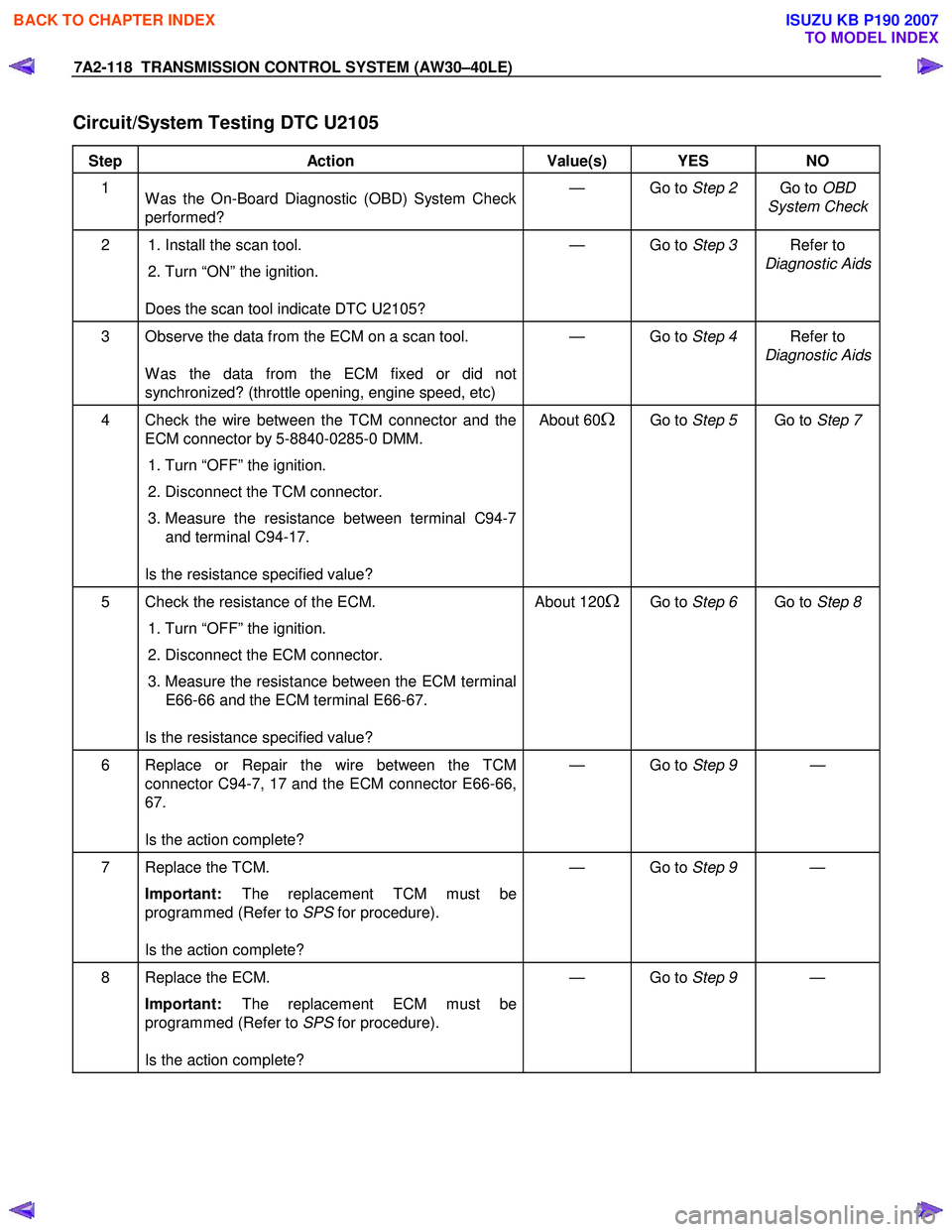
Circuit/System Testing DTC U2105
Step Action Value(s) YES NO
1
W as the On-Board Diagnostic (OBD) System Check
performed? — Go to
Step 2 Go to OBD
System Check
2 1. Install the scan tool.
2. Turn “ON” the ignition.
Does the scan tool indicate DTC U2105? — Go to
Step 3 Refer to
Diagnostic Aids
3 Observe the data from the ECM on a scan tool.
W as the data from the ECM fixed or did not
synchronized? (throttle opening, engine speed, etc) — Go to
Step 4 Refer to
Diagnostic Aids
4 Check the wire between the TCM connector and the ECM connector by 5-8840-0285-0 DMM.
1. Turn “OFF” the ignition.
2. Disconnect the TCM connector.
3. Measure the resistance between terminal C94-7
and terminal C94-17.
Is the resistance specified value? About 60Ω Go to
Step 5 Go to Step 7
5 Check the resistance of the ECM.
1. Turn “OFF” the ignition.
2. Disconnect the ECM connector.
3. Measure the resistance between the ECM terminal
E66-66 and the ECM terminal E66-67.
Is the resistance specified value? About 120ΩGo to
Step 6 Go to Step 8
6 Replace or Repair the wire between the TCM
connector C94-7, 17 and the ECM connector E66-66,
67.
Is the action complete? — Go to
Step 9 —
7 Replace the TCM.
Important: The replacement TCM must be
programmed (Refer to SPS for procedure).
Is the action complete? — Go to
Step 9 —
8 Replace the ECM.
Important: The replacement ECM must be
programmed (Refer to SPS for procedure).
Is the action complete? — Go to
Step 9 —
BACK TO CHAPTER INDEX
TO MODEL INDEX
ISUZU KB P190 2007
Page 4094 of 6020
ON-VEHICLE SERVICE (AW30–40LE) 7A3-9
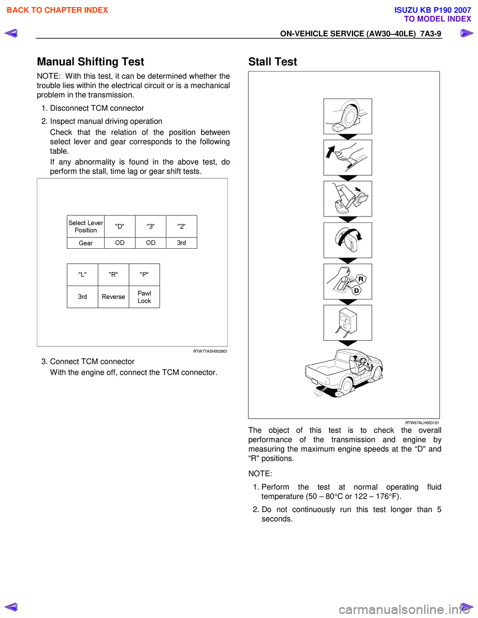
Manual Shifting Test
NOTE: W ith this test, it can be determined whether the
trouble lies within the electrical circuit or is a mechanical
problem in the transmission.
1. Disconnect TCM connector
2. Inspect manual driving operation
Check that the relation of the position between
select lever and gear corresponds to the following
table.
If any abnormality is found in the above test, do
perform the stall, time lag or gear shift tests.
RTW 77ASH002901
3. Connect TCM connector
W ith the engine off, connect the TCM connector.
Stall Test
RTW 67ALH000101
The object of this test is to check the overall
performance of the transmission and engine b
y
measuring the maximum engine speeds at the “D" and
“R" positions.
NOTE:
1. Perform the test at normal operating fluid
temperature (50 – 80 °C or 122 – 176 °F).
2. Do not continuously run this test longer than 5 seconds.
BACK TO CHAPTER INDEX
TO MODEL INDEX
ISUZU KB P190 2007
Page 4097 of 6020
7A3-12 ON-VEHICLE SERVICE (AW30–40LE)
Measure Line Pressure
1. Fully apply the parking brake and chock the four
wheels.
2. Start the engine and check idling rpm.
3. Select into “D" position, step down strongly on the brake pedal with your left foot and while
manipulating the accelerator pedal with the right
foot, measure the line pressures at the engine
speeds specified in the table.
4. In the same manner, perform the test in “R" position.
Line pressure kPa (kg/cm
2/psi) Engine
speed “D" position “R" position
Idling 349 – 408
(3.6 – 4.2 /51 – 59) 577 – 675
(5.9 – 6.9/84 – 98)
Stall 1,206 – 1,353
(12.3–13.8/175–196) 1,646 – 1,979
(16.8–20.2/239–287)
Evaluation
1. If the measured values at all positions are higher
than specified:
• Pressure control solenoid defective
• Primary regulator valve defective
2. If the measured values at all positions are lowe
r
than specified:
• Primary regulator valve defective
• Oil pump defective
• Pressure control solenoid defective
3. If pressure is low in “D" position only:
• “D" position circuit fluid leakage
4. If pressure is low in “R" position only:
• “R" position circuit fluid leakage
Road Test
NOTE: Perform the test at normal operating fluid
temperature (50 – 80 °C or 122 – 176 °F).
“D" Position Test in “NORMAL", and
“POWER" Pattern
Select into the “D" position and hold the accelerator
pedal constant at the 50% and 100% throttle valve
opening positions.
Push in one of the pattern selector buttons and check
the following:
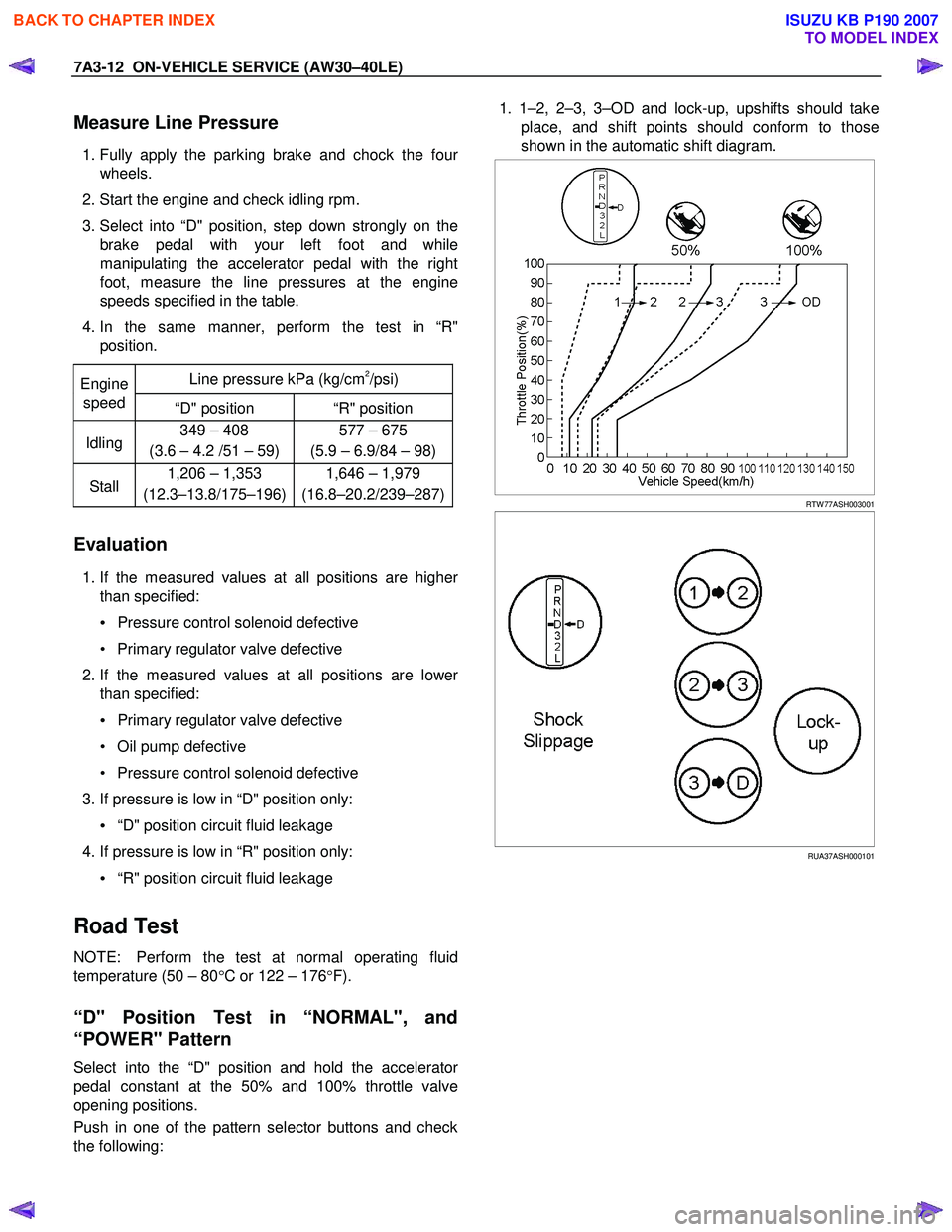
1. 1–2, 2–3, 3–OD and lock-up, upshifts should take
place, and shift points should conform to those
shown in the automatic shift diagram.
RTW 77ASH003001
RUA37ASH000101
BACK TO CHAPTER INDEX
TO MODEL INDEX
ISUZU KB P190 2007
Page 4105 of 6020
7A3-20 ON-VEHICLE SERVICE (AW30–40LE)
Neutral Start Switch (Mode Switch)
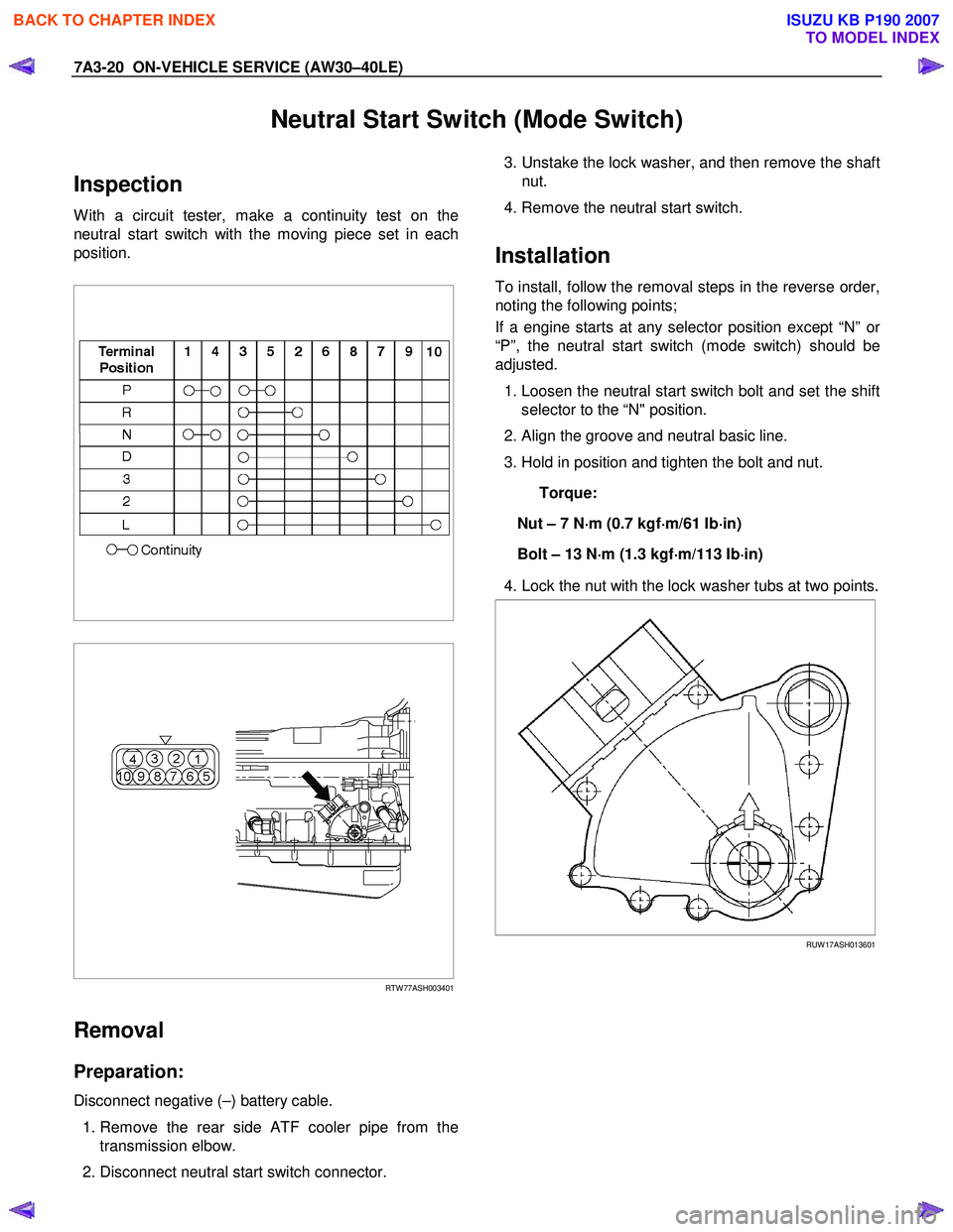
Inspection
W ith a circuit tester, make a continuity test on the
neutral start switch with the moving piece set in each
position.
RTW 77ASH003401
Removal
Preparation:
Disconnect negative (–) battery cable.
1. Remove the rear side ATF cooler pipe from the
transmission elbow.
2. Disconnect neutral start switch connector.
3. Unstake the lock washer, and then remove the shaft
nut.
4. Remove the neutral start switch.
Installation
To install, follow the removal steps in the reverse order,
noting the following points;
If a engine starts at any selector position except “N” o
r
“P”, the neutral start switch (mode switch) should be
adjusted.
1. Loosen the neutral start switch bolt and set the shift
selector to the “N" position.
2. Align the groove and neutral basic line.
3. Hold in position and tighten the bolt and nut.
Torque:
Nut – 7 N ⋅
⋅⋅
⋅
m (0.7 kgf ⋅
⋅⋅
⋅
m/61 Ib ⋅
⋅⋅
⋅
in)
Bolt – 13 N ⋅
⋅⋅
⋅
m (1.3 kgf ⋅
⋅⋅
⋅
m/113 Ib ⋅
⋅⋅
⋅
in)
4. Lock the nut with the lock washer tubs at two points.
RUW 17ASH013601
BACK TO CHAPTER INDEX
TO MODEL INDEX
ISUZU KB P190 2007
Page 4240 of 6020
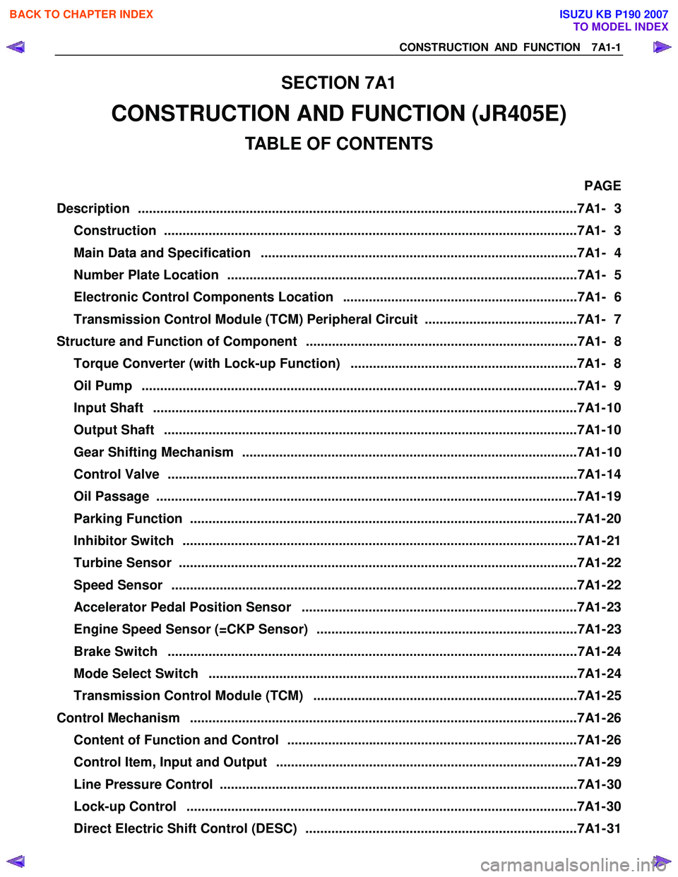
CONSTRUCTION AND FUNCTION 7A1-1
SECTION 7A1
CONSTRUCTION AND FUNCTION (JR405E)
TABLE OF CONTENTS
PAGE
Description ................................................................................................................... ...7A1- 3
Construction ...............................................................................................................7A1 - 3
Main Data and Specification .....................................................................................7A1- 4
Number Plate Location ..............................................................................................7A1- 5
Electronic Control Components Location ...............................................................7A1- 6
Transmission Control Module (TCM) Peripheral Circuit .........................................7A1- 7
Structure and Function of Component .........................................................................7A1- 8
Torque Converter (with Lock-up Function) .............................................................7A1- 8
Oil Pump .....................................................................................................................7 A1- 9
Input Shaft ..................................................................................................................7 A1- 10
Output Shaft ...............................................................................................................7A1 - 10
Gear Shifting Mechanism ..........................................................................................7A1- 10
Control Valve ..............................................................................................................7A1 - 14
Oil Passage .................................................................................................................7A 1- 19
Parking Function ........................................................................................................7A1- 2 0
Inhibitor Switch ..........................................................................................................7A1- 21
Turbine Sensor ...........................................................................................................7A1- 22
Speed Sensor .............................................................................................................7A1- 22
Accelerator Pedal Position Sensor ..........................................................................7A1- 23
Engine Speed Sensor (=CKP Sensor) ......................................................................7A1- 23
Brake Switch ..............................................................................................................7A1- 24
Mode Select Switch ...................................................................................................7A1- 24
Transmission Control Module (TCM) .......................................................................7A1- 25
Control Mechanism ........................................................................................................7A1- 26
Content of Function and Control ..............................................................................7A1- 26
Control Item, Input and Output .................................................................................7A1- 29
Line Pressure Control ................................................................................................7A1- 30
Lock-up Control .........................................................................................................7A1- 3 0
Direct Electric Shift Control (DESC) .........................................................................7A1- 31
BACK TO CHAPTER INDEX
TO MODEL INDEX
ISUZU KB P190 2007
Page 4241 of 6020
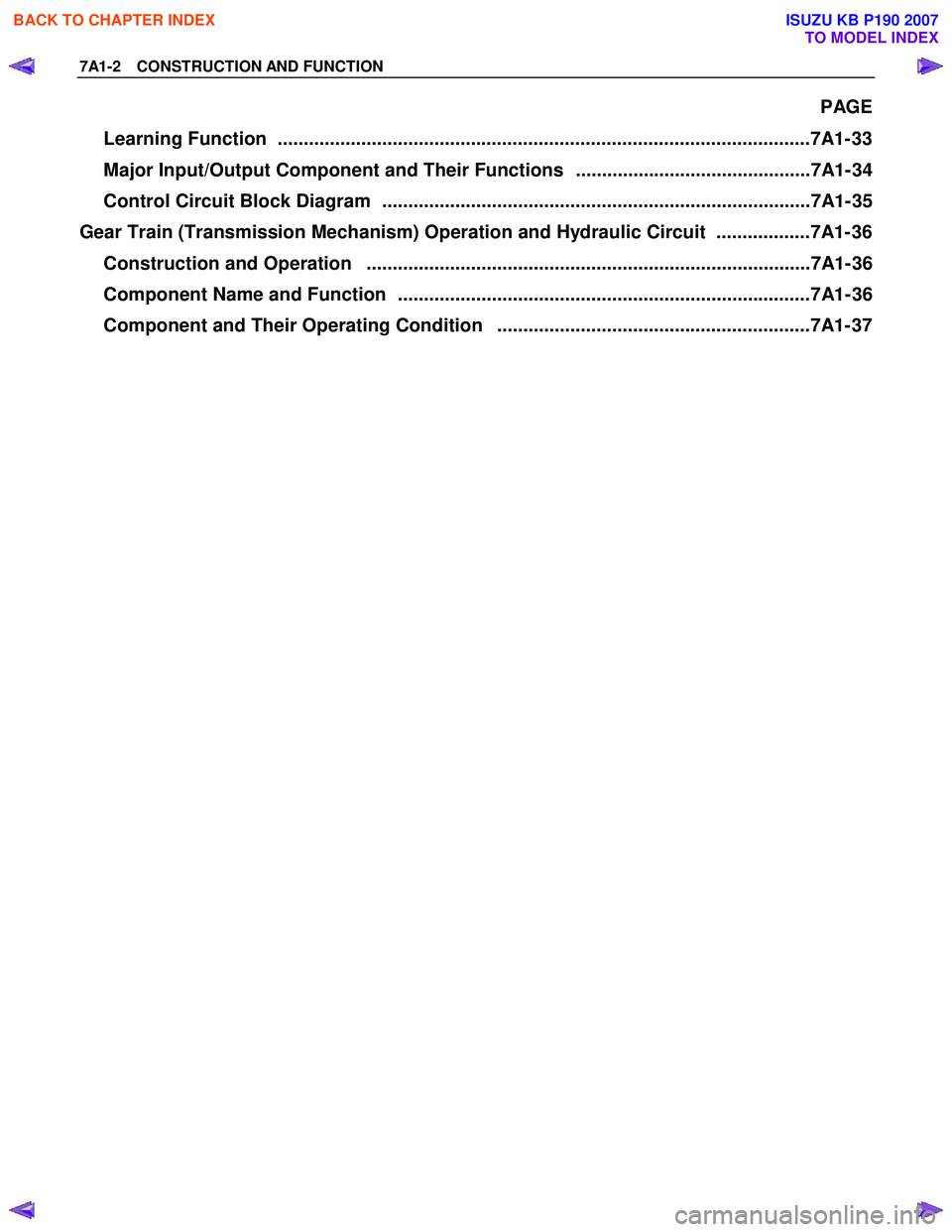
7A1-2 CONSTRUCTION AND FUNCTION
PAGE
Learning Function ......................................................................................................7A1- 33
Major Input/Output Component and Their Functions .............................................7A1- 34
Control Circuit Block Diagram ..................................................................................7A1- 35
Gear Train (Transmission Mechanism) Operation and Hydraulic Circuit ..................7A1- 36
Construction and Operation .....................................................................................7A1- 36
Component Name and Function ...............................................................................7A1- 36
Component and Their Operating Condition ............................................................7A1- 37
BACK TO CHAPTER INDEX
TO MODEL INDEX
ISUZU KB P190 2007