body ISUZU KB P190 2007 Workshop Repair Manual
[x] Cancel search | Manufacturer: ISUZU, Model Year: 2007, Model line: KB P190, Model: ISUZU KB P190 2007Pages: 6020, PDF Size: 70.23 MB
Page 5765 of 6020
CAB 10-7
Important Operation - Removal
3. Rear Window
Remove the rear window, carefully following the steps listed
below :
1) Use a knife to cut through part of the adhesive caulking material.
2) Secure one end of a piece of steel piano wire (0.02 inches in diameter) to a piece of wood that can serve as a handle.
3) Use a pair of needle nose pliers to insert the other end o
f
the piano wire through the adhesive caulking material at the
edge of the rear window.
4) Secure the other end of the piano wire to another piece o
f
wood.
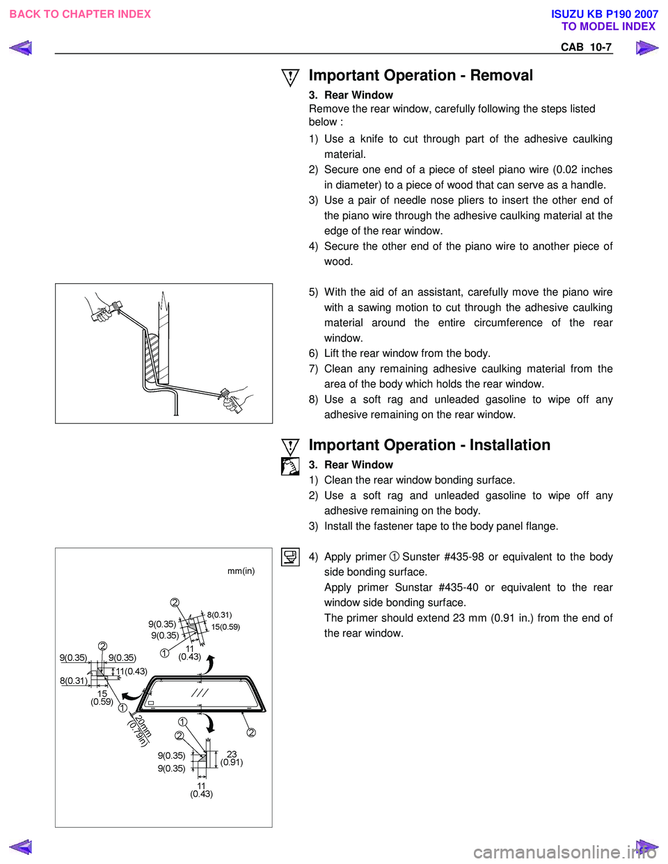
5) W ith the aid of an assistant, carefully move the piano wire
with a sawing motion to cut through the adhesive caulking
material around the entire circumference of the rea
r
window.
6) Lift the rear window from the body.
7) Clean any remaining adhesive caulking material from the area of the body which holds the rear window.
8) Use a soft rag and unleaded gasoline to wipe off an
y
adhesive remaining on the rear window.
Important Operation - Installation
3. Rear Window
1) Clean the rear window bonding surface.
2) Use a soft rag and unleaded gasoline to wipe off an
y
adhesive remaining on the body.
3) Install the fastener tape to the body panel flange.
4) Apply primer 1 Sunster #435-98 or equivalent to the body
side bonding surface.
Apply primer Sunstar #435-40 or equivalent to the rea
r
window side bonding surface.
The primer should extend 23 mm (0.91 in.) from the end o
f
the rear window.
BACK TO CHAPTER INDEX TO MODEL INDEX
ISUZU KB P190 2007
Page 5768 of 6020
10-10 CAB
RUW 5A0SH003001
2. Check Arm Screw
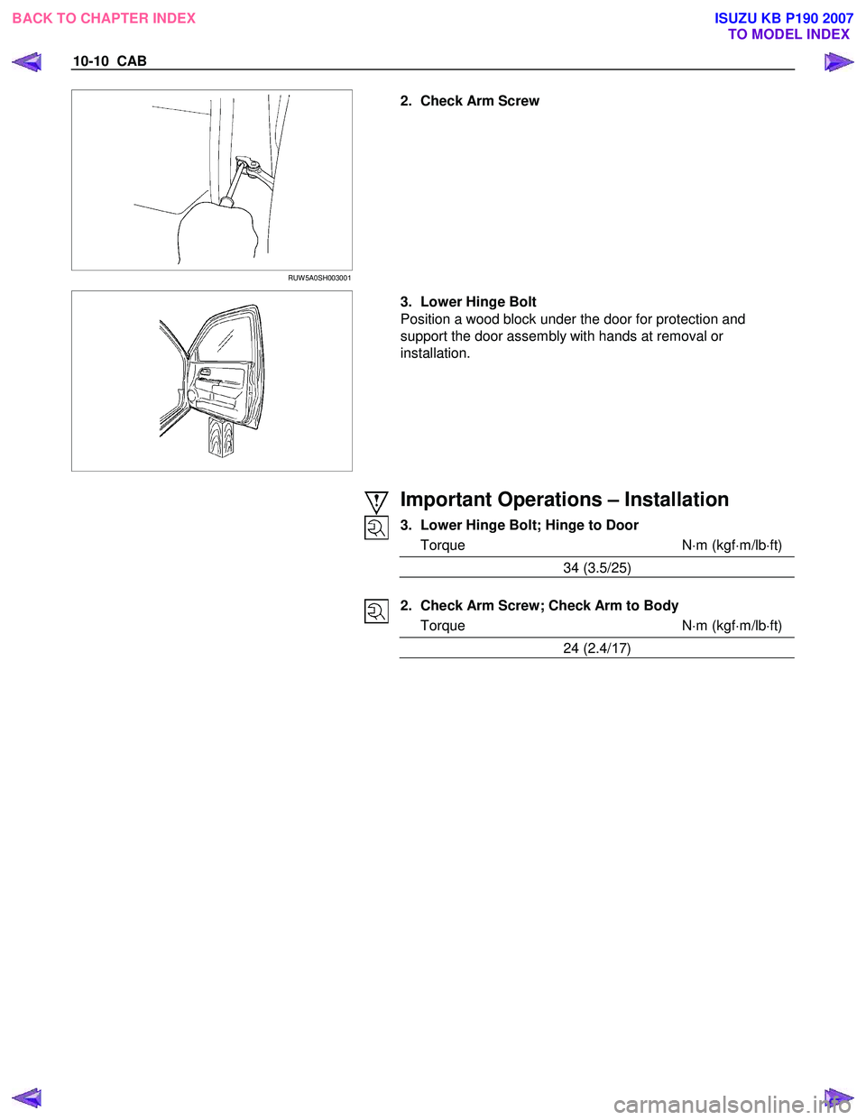
3. Lower Hinge Bolt
Position a wood block under the door for protection and
support the door assembly with hands at removal or
installation.
Important Operations – Installation
3. Lower Hinge Bolt; Hinge to Door
Torque N ⋅m (kgf ⋅m/lb ⋅ft)
34 (3.5/25)
2. Check Arm Screw; Check Arm to Body
Torque N ⋅m (kgf ⋅m/lb ⋅ft)
24 (2.4/ 17)
BACK TO CHAPTER INDEX
TO MODEL INDEX
ISUZU KB P190 2007
Page 5776 of 6020
10-18 CAB
ADJUSTMENT (FRONT)
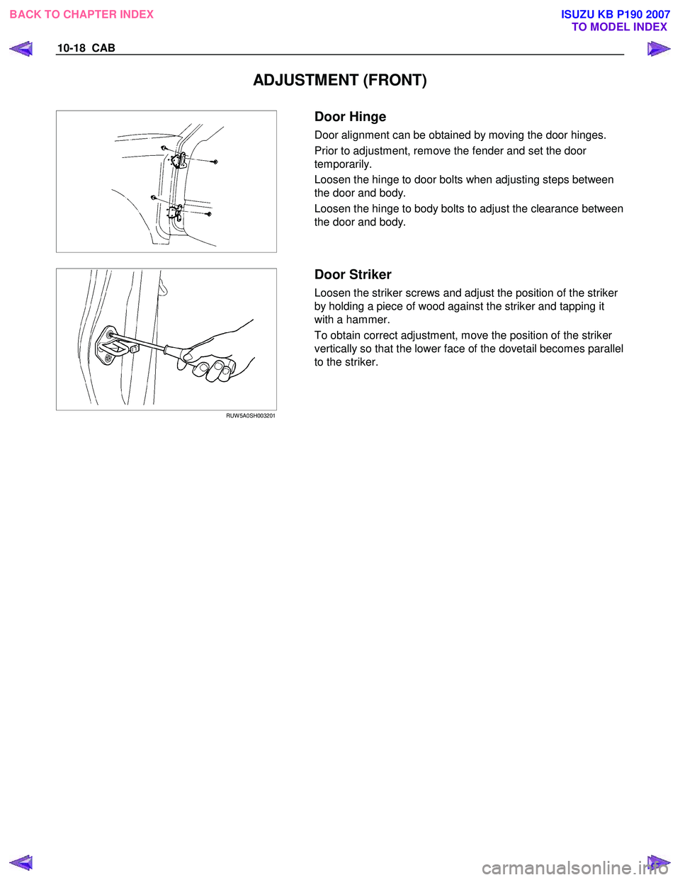
Door Hinge
Door alignment can be obtained by moving the door hinges.
Prior to adjustment, remove the fender and set the door
temporarily.
Loosen the hinge to door bolts when adjusting steps between
the door and body.
Loosen the hinge to body bolts to adjust the clearance between
the door and body.
RUW 5A0SH003201
Door Striker
Loosen the striker screws and adjust the position of the striker
by holding a piece of wood against the striker and tapping it
with a hammer.
To obtain correct adjustment, move the position of the striker
vertically so that the lower face of the dovetail becomes parallel
to the striker.
BACK TO CHAPTER INDEX TO MODEL INDEX
ISUZU KB P190 2007
Page 5778 of 6020
10-20 CAB
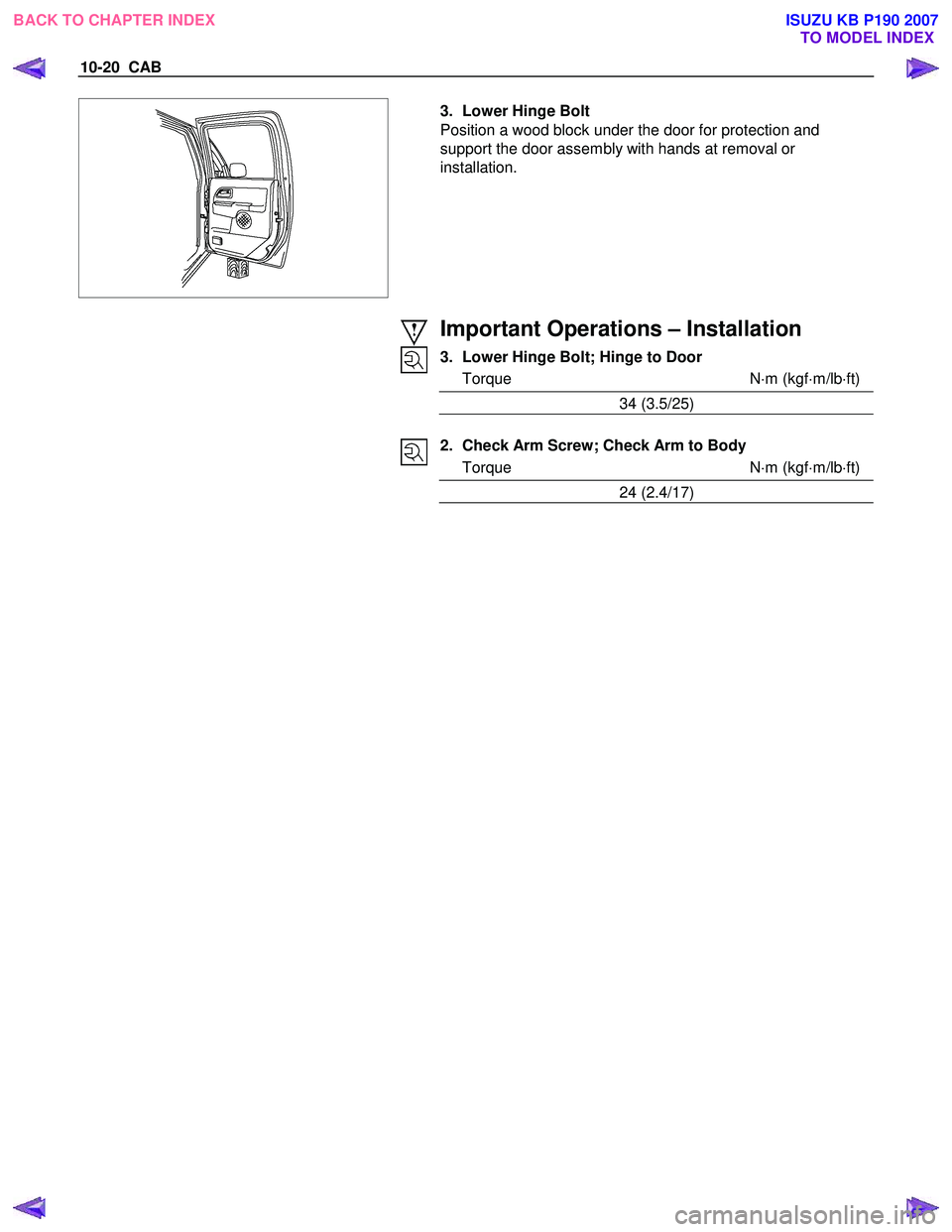
3. Lower Hinge Bolt
Position a wood block under the door for protection and
support the door assembly with hands at removal or
installation.
Important Operations – Installation
3. Lower Hinge Bolt; Hinge to Door
Torque N ⋅m (kgf ⋅m/lb ⋅ft)
34 (3.5/25)
2. Check Arm Screw; Check Arm to Body
Torque N ⋅m (kgf ⋅m/lb ⋅ft)
24 (2.4/17)
BACK TO CHAPTER INDEX TO MODEL INDEX
ISUZU KB P190 2007
Page 5784 of 6020
10-26 CAB
ADJUSTMENT (REAR)
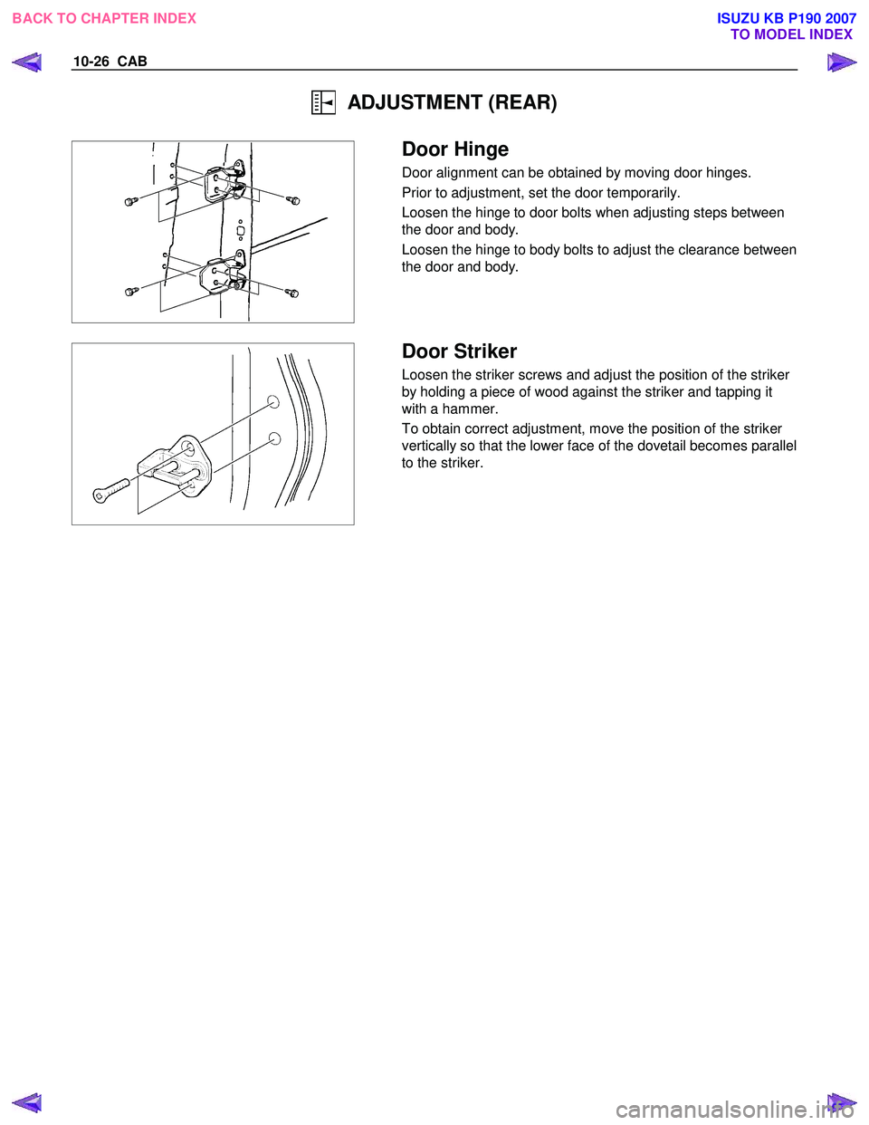
Door Hinge
Door alignment can be obtained by moving door hinges.
Prior to adjustment, set the door temporarily.
Loosen the hinge to door bolts when adjusting steps between
the door and body.
Loosen the hinge to body bolts to adjust the clearance between
the door and body.
Door Striker
Loosen the striker screws and adjust the position of the striker
by holding a piece of wood against the striker and tapping it
with a hammer.
To obtain correct adjustment, move the position of the striker
vertically so that the lower face of the dovetail becomes parallel
to the striker.
BACK TO CHAPTER INDEX TO MODEL INDEX
ISUZU KB P190 2007
Page 5788 of 6020
10-30 CAB
RUW 5A0SH002701
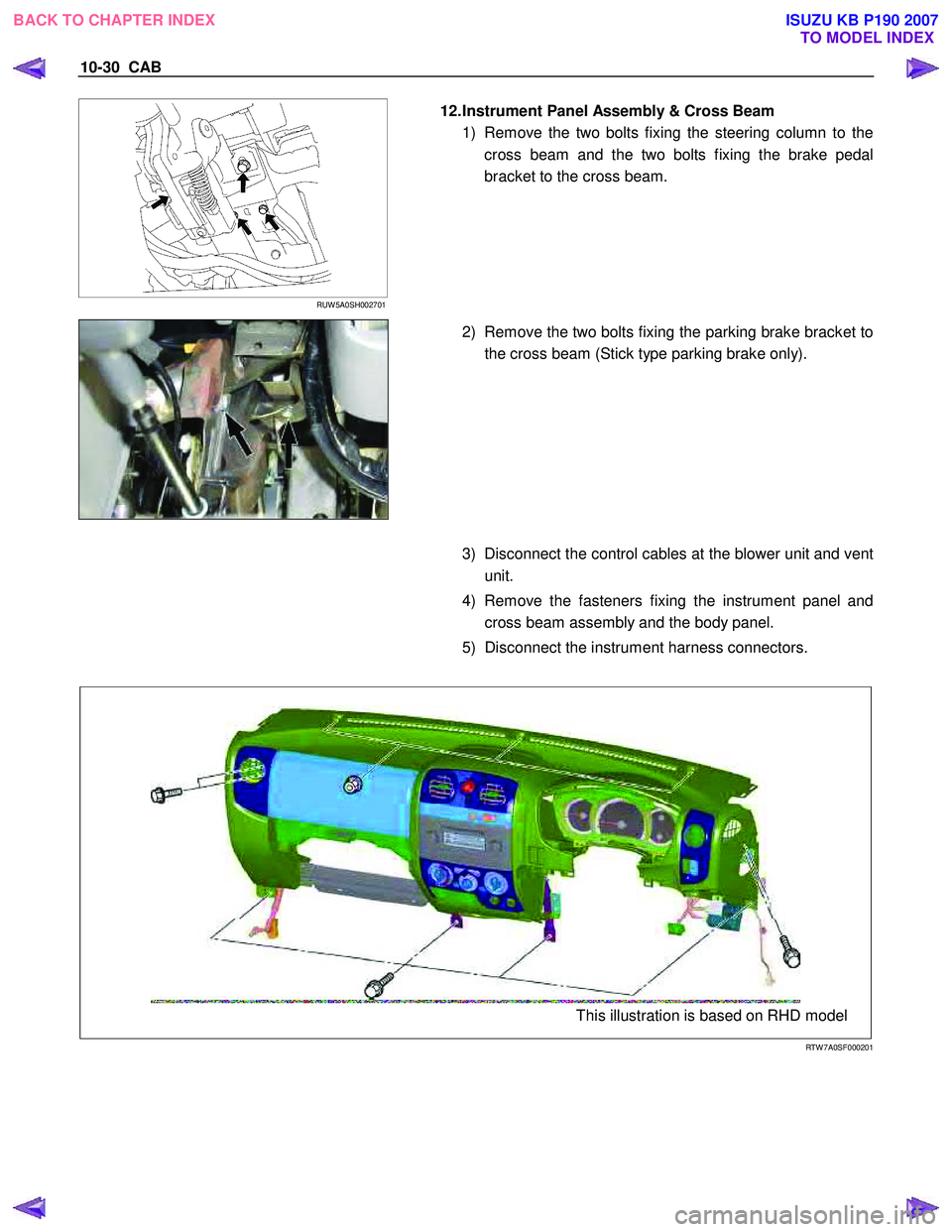
12. Instrument Panel Assembly & Cross Beam
1) Remove the two bolts fixing the steering column to the cross beam and the two bolts fixing the brake pedal
bracket to the cross beam.
2) Remove the two bolts fixing the parking brake bracket to
the cross beam (Stick type parking brake only).
3) Disconnect the control cables at the blower unit and vent
unit.
4) Remove the fasteners fixing the instrument panel and cross beam assembly and the body panel.
5) Disconnect the instrument harness connectors.
This illustration is based on RHD model
RTW 7A0SF000201
BACK TO CHAPTER INDEX TO MODEL INDEX
ISUZU KB P190 2007
Page 5792 of 6020
10-34 CAB
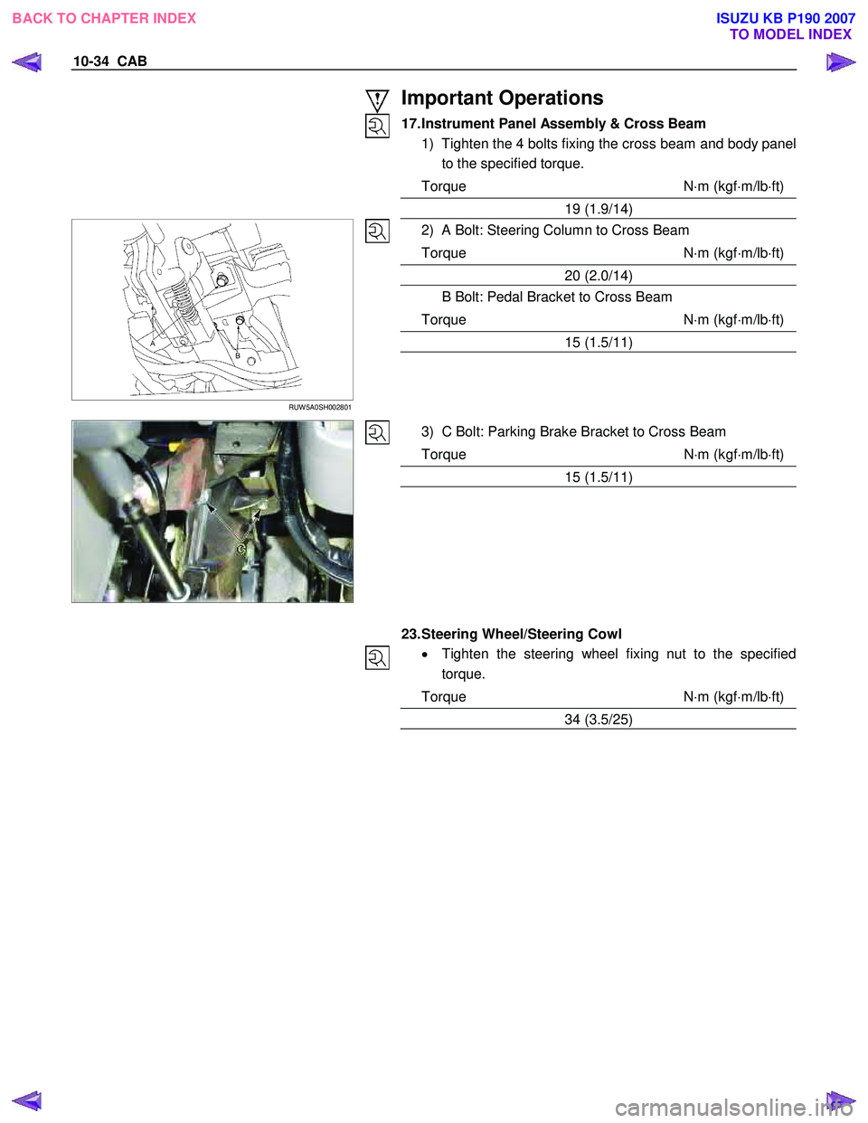
Important Operations
17. Instrument Panel Assembly & Cross Beam 1) Tighten the 4 bolts fixing the cross beam and body panel to the specified torque.
Torque N ⋅m (kgf ⋅m/lb ⋅ft)
19 (1.9/14)
RUW 5A0SH002801
2) A Bolt: Steering Column to Cross Beam
Torque N ⋅m (kgf ⋅m/lb ⋅ft)
20 (2.0/14)
B Bolt: Pedal Bracket to Cross Beam
Torque N ⋅m (kgf ⋅m/lb ⋅ft)
15 (1.5/11)
3) C Bolt: Parking Brake Bracket to Cross Beam
Torque N ⋅m (kgf ⋅m/lb ⋅ft)
15 (1.5/11)
23. Steering Wheel/Steering Cowl • Tighten the steering wheel fixing nut to the specified
torque.
Torque N ⋅m (kgf ⋅m/lb ⋅ft)
34 (3.5/25)
BACK TO CHAPTER INDEX TO MODEL INDEX
ISUZU KB P190 2007
Page 5803 of 6020
CAB 10-45
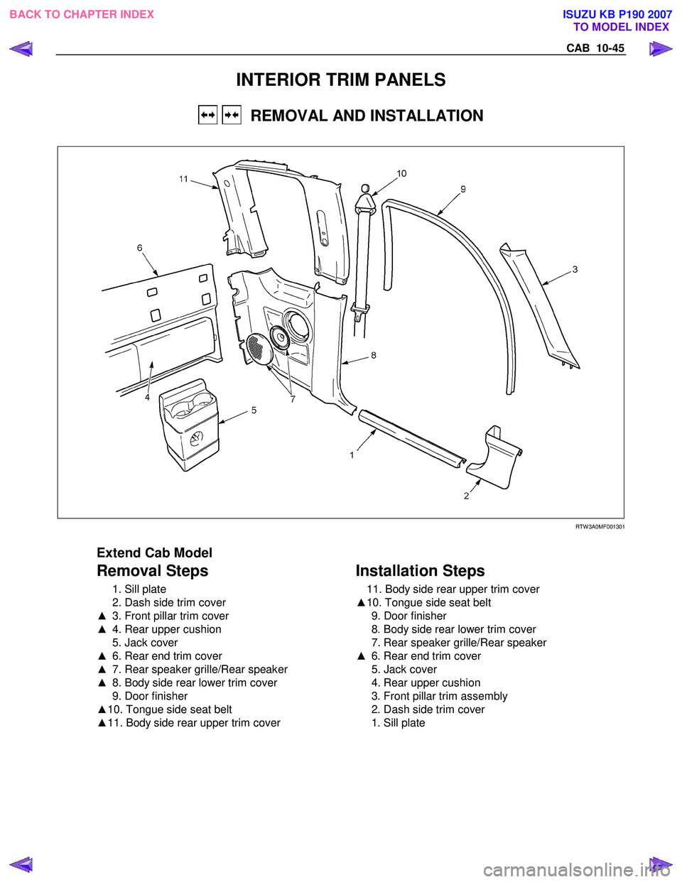
INTERIOR TRIM PANELS
REMOVAL AND INSTALLATION
RTW 3A0MF001301
Extend Cab Model
Removal Steps
1. Sill plate
2. Dash side trim cover
▲ 3. Front pillar trim cover
▲ 4. Rear upper cushion
5. Jack cover
▲ 6. Rear end trim cover
▲ 7. Rear speaker grille/Rear speaker
▲ 8. Body side rear lower trim cover
9. Door finisher
▲ 10. Tongue side seat belt
▲ 11. Body side rear upper trim cover
Installation Steps
11. Body side rear upper trim cover
▲ 10. Tongue side seat belt
9. Door finisher
8. Body side rear lower trim cover
7. Rear speaker grille/Rear speaker
▲ 6. Rear end trim cover
5. Jack cover
4. Rear upper cushion
3. Front pillar trim assembly
2. Dash side trim cover
1. Sill plate
BACK TO CHAPTER INDEX TO MODEL INDEX
ISUZU KB P190 2007
Page 5804 of 6020
10-46 CAB
RTW 710SH000501
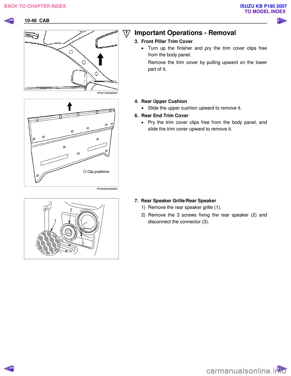
Important Operations - Removal
3. Front Pillar Trim Cover • Turn up the finisher and pry the trim cover clips free
from the body panel.
Remove the trim cover by pulling upward on the lowe
r
part of it.
RTW 5A0SH000601
4. Rear Upper Cushion
• Slide the upper cushion upward to remove it.
6. Rear End Trim Cover • Pry the trim cover clips free from the body panel, and
slide the trim cover upward to remove it.
7. Rear Speaker Grille/Rear Speaker
1) Remove the rear speaker grille (1).
2) Remove the 3 screws fixing the rear speaker (2) and disconnect the connector (3).
BACK TO CHAPTER INDEX TO MODEL INDEX
ISUZU KB P190 2007
Page 5805 of 6020
CAB 10-47
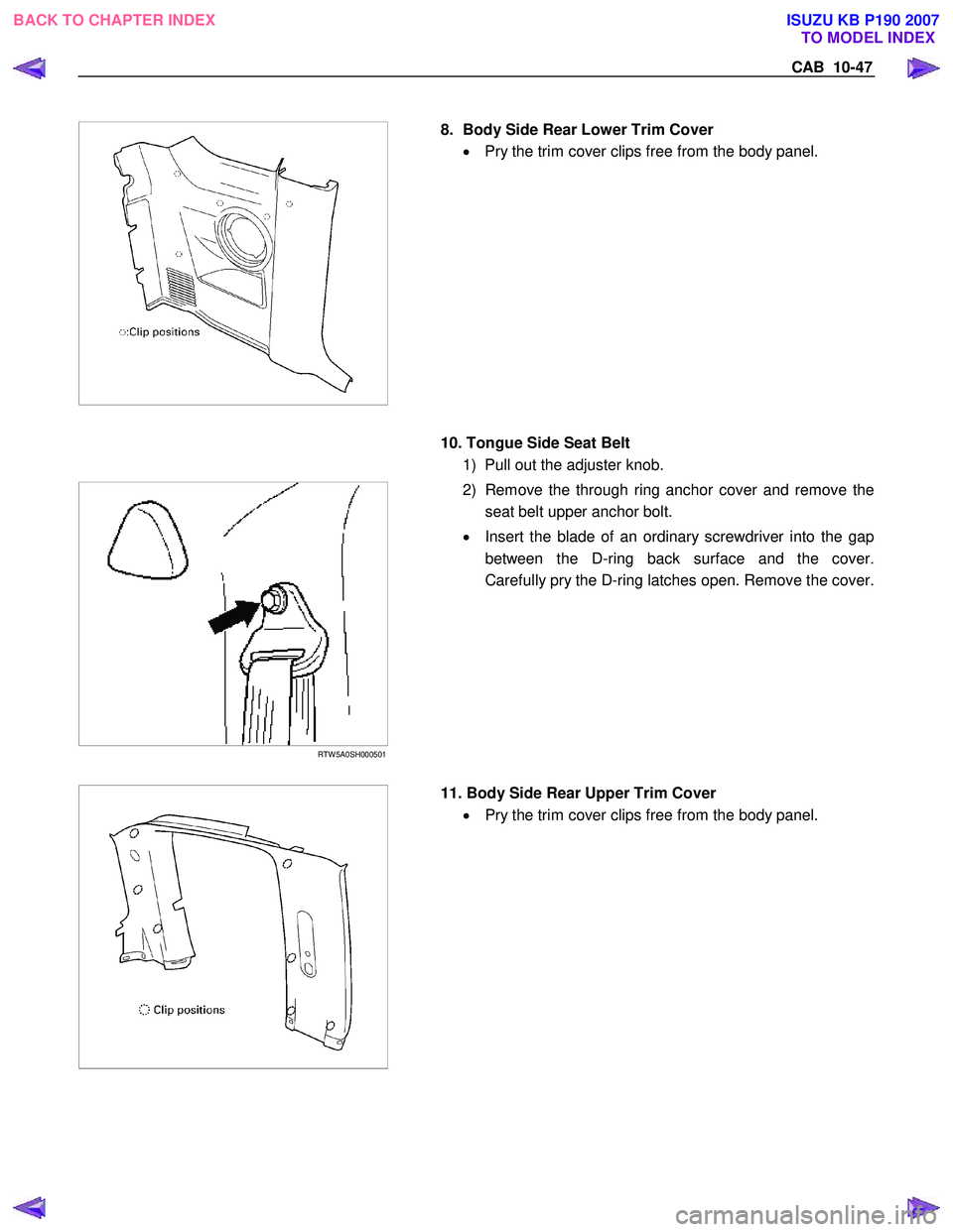
8. Body Side Rear Lower Trim Cover
• Pry the trim cover clips free from the body panel.
10. Tongue Side Seat Belt
1) Pull out the adjuster knob.
RTW 5A0SH000501
2) Remove the through ring anchor cover and remove the
seat belt upper anchor bolt.
• Insert the blade of an ordinary screwdriver into the gap
between the D-ring back surface and the cover.
Carefully pry the D-ring latches open. Remove the cover.
11. Body Side Rear Upper Trim Cover
• Pry the trim cover clips free from the body panel.
BACK TO CHAPTER INDEX
TO MODEL INDEX
ISUZU KB P190 2007