body ISUZU KB P190 2007 Workshop Repair Manual
[x] Cancel search | Manufacturer: ISUZU, Model Year: 2007, Model line: KB P190, Model: ISUZU KB P190 2007Pages: 6020, PDF Size: 70.23 MB
Page 5589 of 6020

Cruise Control – HFV6 Page 8C–11
Step Action Yes No
3 On Tech 2 select
Engine / V6 Engine / Diagnostic Trouble codes / Read DTCs’.
Are there any set DTC’s? Go to the
appropriate DTC table in 6C1-2 Engine
Management – V6 – Diagnostics Go to Step 4
4 Is the instrument cluster assembly functioning correctly? Go to 2.4
Cruise
Control Inoperative / Malfunctioning Refer to 8A
Electrical – Body
and Chassis.
When all diagnosis and repairs are completed, clear all DTCs and check the system for correct operation.
BACK TO CHAPTER INDEX TO MODEL INDEXISUZU KB P190 2007
Page 5593 of 6020

Cruise Control – HFV6 Page 8C–15
Step Action Yes No
3 Check the ignition supply circuits to the Stop Lamp Switch assembly
connector C – 44 pin 1 is serviceable using a multimeter set to
measure voltage, refer to 2.3 W iring Diagrams in this Section
Is there a +12 volt signal present at connector C – 44 pin 1?
Go to Step 4 Replace the faulty
fusible link Main,
IG2 or Stop Light fuse (refer to Note 1).
If either of the
fusible links or fuse blows again, repair
or replace the faulty circuit (refer to
Note 1)
4 1 Connect Tech 2 to the DLC.
2 On Tech 2 select: Body / Powertrain Interface Module / Diagnostic Data
Display.
3 Scroll to Cruise Main Switch.
4 W hile monitoring Tech 2, press the cruise control switch ON– OFF button.
Does Tech 2 display the following:
• Inactive and Active as the cruise control switch is pressed?
Go to Step 5 Go to Step 11
5 1 Scroll to Cruise Resume Switch.
2 While monitoring Tech 2, rotate the cruise control switch.
Does Tech 2 display the following:
• Inactive when the cruise control switch is in the neutral
position?
• Res / Acc when the cruise control switch is rotated to the RES–
ACC. Position? Go to Step 6 Go to Step 12
6
1 Scroll to Cruise Set Switch.
2 W hile monitoring Tech 2, press the cruise control switch.
Does Tech 2 display the following:
• Inactive when the cruise control switch is in the neutral
position?
• Set / Coast when the cruise control switch is pressed to the
SET–COAST position? Go to Step 7 Go to Step 13
7 1 Scroll to Cruise Cancel Switch.
2 While monitoring Tech 2, rotate the cruise control switch.
Does Tech 2 display the following:
• Inactive when the cruise control switch is in the neutral
position?
• Cancel when the cruise control switch is rotated to the CANCEL
position? Go to Step 8 Go to Step 14
BACK TO CHAPTER INDEX
TO MODEL INDEXISUZU KB P190 2007
Page 5628 of 6020

ACCESSORIES 9-23
No. Connector face No. Connector face
D-22
White
Tweeter -LH P-1
SilverBattery (+)
H-14
White
Rear body ∼ Rear door -LH P-2
SilverRelay & Fuse box
H-16
White
Rear body ∼ Rear door -RH P-5
SilverBattery (-)
H-18
White
Engine room ∼ INST P-6
SilverBody earth
H-36
White
INST ~ Front door-RH P-10
SilverEngine ground
H-37
White
INST ~ Front door-LH R-7
BlackRear speaker -LH
H-39
White
INST ~ Front door-LH R-8
BlackRear speaker -RH
H-42
White
INST ~ Front door-driver
H-43
INST ~ Body
H-43
White
INST ~ Body
BACK TO CHAPTER INDEX TO MODEL INDEXISUZU KB P190 2007
Page 5636 of 6020
SUPPLEMENTAL RESTRAINT SYSTEM 9A-1
SECTION 9A
SUPPLEMENTAL RESTRAINT SYSTEM (SRS)
TABLE OF CONTENTS
PAGE
Service Precaution ....................................................................................................... 9A- 4
General Description...................................................................................................... 9A- 4 Restraint Devices ..................................................................................................... 9A- 4
System Description .................................................................................................. 9A- 5
Circuit Diagram ............................................................................................................. 9A- 6
SRS Component And Wiring Location View .............................................................. 9A- 10
Component Description ............................................................................................... 9A- 14 SRS Control Unit ...................................................................................................... 9A- 14
"SRS" Warning Lamp .............................................................................................. 9A- 14
SRS Coil Assembly .................................................................................................. 9A- 15
Air Bag Assemblies.................................................................................................. 9A- 15
Steering Column ...................................................................................................... 9A- 16
Knee Bolster ............................................................................................................. 9A- 16
Definitions .................................................................................................................... . 9A- 16
Diagnosis...................................................................................................................... . 9A- 18
Diagnostic Trouble Codes ....................................................................................... 9A- 18
Scan Tool Diagnostics............................................................................................. 9A- 18
Use Of Special Tools ............................................................................................... 9A- 18
SRS Connec tor Body Face Vie ws ............................................................................. ..9 A- 19
Repairs And Inspec tions Required After A n A ccident ............................................ ..9 A- 20
Accident With Deployment-Component Replacement And Inspections ............. 9A- 20
Accident With or Without Deployment-Component Inspection ........................... 9A- 20
SRS Control Unit Replacement Guidelines ........................................................... 9A- 20
Wiring Damage ......................................................................................................... 9A- 20
SRS Connector (Plastic Body And Terminal Metal Pin) Damage ......................... 9A- 20
SRS Wire Pigtail Damage ........................................................................................ 9A- 20
PAGE 1 OF 3
BACK TO CHAPTER INDEX TO MODEL INDEXISUZU KB P190 2007
Page 5652 of 6020
SUPPLEMENTAL RESTRAINT SYSTEM 9A-17
“Continuous Monitoring”
Tests are performed by the SRS control unit on the
SRS every 100 milliseconds while “Ignition 1” voltage
is in the normal operating voltage range at the SRS
control unit.
Data Link Connector (DLC)
Formerly “DLC”, a connector which allows
communication with an external computer, such as a
scan tool.
Datum Line
A base line parallel to the plane of the underbody or
frame from which all vertical measurements originate.
Deploy
To inflate the air bag.
Deployment Loops
The circuits which supply current to the air bag
assemblies to deploy the air bag.
Diagnostic Trouble Code (DTC)
Formerly “Code”, a numerical designator used by the
SRS control unit to indicate specific SRS malfunctions.
Driver Current Source
An output of the SRS control unit which applies current
into the driver air bag assembly circuit during the
“Initiator Assembly Resistance Test”.
Driver Air Bag Assembly
An assembly located in the steering wheel hub
consisting of an inflatable bag, an inflator and an
initiator.
EEPROM
Electrically Erasable Programmable Read Onl
y
Memory. Memory which retains its contents when
power is removed from the SRS control unit.
Ignition Cycle
The voltage at the SRS control unit “Ignition 1” input,
with ignition switch “ON”, is within the normal operating
voltage range for at least ten seconds before turning
the ignition switch “OFF”.
Ignition 1
A battery voltage (B+) circuit which is only powered
when the ignition switch is in the ON, or START
position.
Initiator
The electrical component inside the air bag assembl
y
which, when sufficient current flows, sets off the
chemical reaction that inflates the air bag.
“Initiator Assembly Resistance Test”
Tests are performed once for each ignition cycle when
no malfunctions are detected during “Turn–ON” o
r
“Continuous Monitoring”. This test checks for the
correct SRS control unit configuration for the vehicle,
shorts to “Ignition 1” in the deployment loops, high
resistance or opens in the “Driver Side” and
“Passenger Side” circuits and measures the resistance
of the inflator assembly consisting of 1) Initiators, 2)
SRS coil assembly (driver side only), 3) Connectors
and associated wiring.
Normal Operating Voltage Range
The voltage measured between the SRS control unit
“Ignition 1” terminals and “Ground” terminals is
between 9 and 16 volts.
Passenger Current Source
An output of the SRS control unit which applies current
into the passenger air bag assembly circuit during the
“Initiator Assembly Resistance Test”.
Passenger Air Bag Assembly
An assembly located in the front of the passenger side
of the instrument panel consisting of an inflatable bag,
an inflator and an initiator.
Scan Tool
An external computer used to read diagnostic
information from on–board computers via the data link
connector.
SRS control unit
SRS control unit which provides reserve energy to the
deployment loops, deploys the air bags when required
and performs diagnostic monitoring of all SRS
components.
Serial Data
Information representing the status of the SRS.
SRS
Supplemental Restraint System.
SRS Coil Assembly
An assembly of two current–carrying coils in the drive
r
deployment loop that allows the rotation of the steering
wheel while maintaining the continuous contact of the
driver deployment loop to the driver air bag assembly.
SRS Wiring Harness
The wires and connectors that electrically connect the
components in the SRS.
“Turn–ON”
Test which the SRS control unit performs on the SRS
once during each ignition cycle immediately afte
r
“Ignition 1” voltage is applied to the SRS control unit
and before “Continuous Monitoring”.
BACK TO CHAPTER INDEX TO MODEL INDEXISUZU KB P190 2007
Page 5654 of 6020
SUPPLEMENTAL RESTRAINT SYSTEM 9A-19
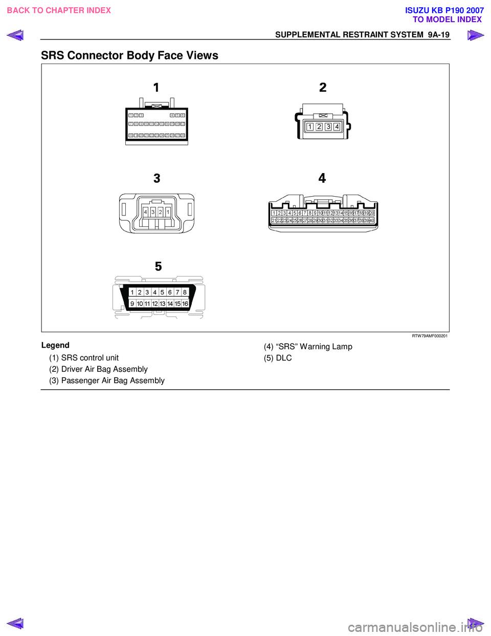
SRS Connector Body Face Views
RTW 79AMF000201
Legend
(1) SRS control unit
(2) Driver Air Bag Assembly
(3) Passenger Air Bag Assembly
(4) “SRS” W arning Lamp
(5) DLC
BACK TO CHAPTER INDEX TO MODEL INDEXISUZU KB P190 2007
Page 5655 of 6020

9A-20 SUPPLEMENTAL RESTRAINT SYSTEM
Repairs And Inspections Required
After An Accident
If any SRS components are damaged, they must be
replaced. If SRS component mounting points are
damaged, they must be replaced.
• Never use SRS parts from another vehicle. This does not include remanufactured parts purchased
from an authorized dealer; they may be used fo
r
SRS repairs.
• Do not attempt to service the SRS control unit, the SRS coil assembly, or the air bag assembly.
Service of these items is by replacement only.
• Verify the part number of the replacement air bag assembly.
CAUTION: Never use the air bag assembly from
another vehicle or different model year air bag
assembly.
Use only a new air bag assembly matched to the
TFR/S which is being repaired.
CAUTION: Proper operation of the sensors and
supplemental restraint system (SRS) requires that
any repairs to the vehicle structure return it to the
original production configuration. Deployment
requires, at a minimum, replacement of the SRS
control unit, air bag assembly and dimensional
inspection of the steering column. Any visible
damage to the SRS control unit mounting bracket
(s) requires replacement, and the steering column
must be dimensionally inspected, whethe
r
deployment occurred or not.
Accident With Deployment – Component
Replacement And Inspections
Certain SRS components must be replaced or
inspected for damage after a frontal crash involving air
bag deployment. Those components are:
• Air bag assembly
• SRS control unit
CAUTION: Refer to “SRS control unit Replacement
Guidelines” below for important information on
SRS control unit replacement in both deployment
and non-deployment crashes.
• SRS coil assembly — Inspect wiring and connecto
r
for any signs of scorching, melting, or damage due
to excessive heat. Replace if damaged. Refer to
section “SRS Coil Assembly” in this manual.
Accident With or Without Deployment –
Component Inspection
Certain SRS system components and rotation parts
must be inspected after any crash, whether the air bag
has been deployed or not. Those components are:
• Steering column — Refer to Inspection Required “After an Accident” in this manual.
• Knee bolsters and mounting points — Inspect fo
r
any distortion, bending, cracking, or other damage.
• I/P steering column reinforcement plate — Inspect for any distortion, bending, cracking, or othe
r
damage.
• I/P braces — Inspect for any distortion, bending, cracking, or other damage.
• Seat belts and mounting points — Refer to “Seat Belts” in Section “Seat Belt” of this workshop
manual.
SRS Control Unit Replacement Guidelines
SRS control unit replacement policy requires
replacement of the SRS control unit after a crash
involving air bag deployment when the “SRS W arning
Lamp” turned “ON”, the “SRS Diagnosis” should be
done according to Section “Restraint Control System.”
Wiring Damage
If any SRS wire harness is damaged, it should be
replaced. Don't repair the SRS harness. It is
replacement only.
SRS Connector (Plastic Body And
Terminal Metal Pin) Damage
If any connector or terminal in the SRS wire harness
(except pigtails) is damaged, it should be replaced.
SRS Wire Pigtail Damage
If the wiring pigtail (a wire or wires attached directly to
the device, not by a connector) is damaged, the entire
component (with pigtail) must be replaced. Examples
of “pigtail” components are the driver air bag
assembly, the passenger air bag assembly, and the
SRS coil assembly.
BACK TO CHAPTER INDEX TO MODEL INDEXISUZU KB P190 2007
Page 5761 of 6020
CAB 10-3
RUW 5A0SH002901
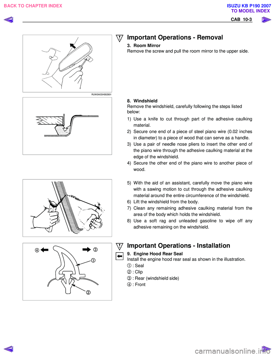
Important Operations - Removal
3. Room Mirror
Remove the screw and pull the room mirror to the upper side.
8. Windshield
Remove the windshield, carefully following the steps listed
below:
1) Use a knife to cut through part of the adhesive caulking material.
2) Secure one end of a piece of steel piano wire (0.02 inches in diameter) to a piece of wood that can serve as a handle.
3) Use a pair of needle nose pliers to insert the other end o
f
the piano wire through the adhesive caulking material at the
edge of the windshield.
4) Secure the other end of the piano wire to another piece o
f
wood.
5) W ith the aid of an assistant, carefully move the piano wire
with a sawing motion to cut through the adhesive caulking
material around the entire circumference of the windshield.
6) Lift the windshield from the body.
7) Clean any remaining adhesive caulking material from the area of the body which holds the windshield.
8) Use a soft rag and unleaded gasoline to wipe off an
y
adhesive remaining on the windshield.
Important Operations - Installation
9. Engine Hood Rear Seal
Install the engine hood rear seal as shown in the illustration.
1 : Seal
2 : Clip
3 : Rear (windshield side)
4 : Front
BACK TO CHAPTER INDEX TO MODEL INDEX
ISUZU KB P190 2007
Page 5762 of 6020
10-4 CAB
8. Windshield
1) Clean the windshield bonding surface.
2) Use a soft rag and unleaded gasoline to wipe off an
y
adhesive remaining on the body.
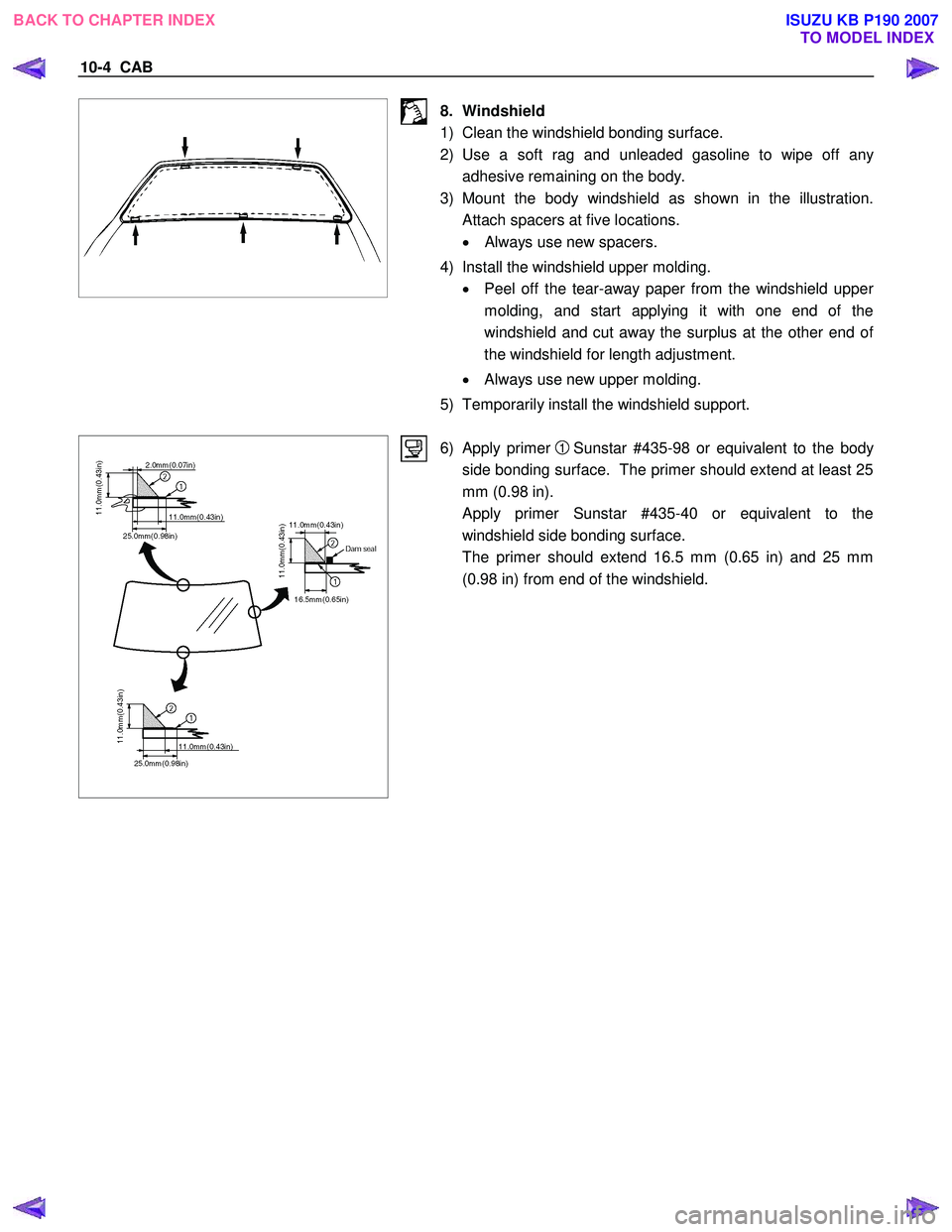
3) Mount the body windshield as shown in the illustration. Attach spacers at five locations.
• Always use new spacers.
4) Install the windshield upper molding. • Peel off the tear-away paper from the windshield uppe
r
molding, and start applying it with one end of the
windshield and cut away the surplus at the other end o
f
the windshield for length adjustment.
• Always use new upper molding.
5) Temporarily install the windshield support.
6) Apply primer
1 Sunstar #435-98 or equivalent to the body
side bonding surface. The primer should extend at least 25
mm (0.98 in).
Apply primer Sunstar #435-40 or equivalent to the windshield side bonding surface.
The primer should extend 16.5 mm (0.65 in) and 25 mm (0.98 in) from end of the windshield.
BACK TO CHAPTER INDEX TO MODEL INDEX
ISUZU KB P190 2007
Page 5763 of 6020
CAB 10-5
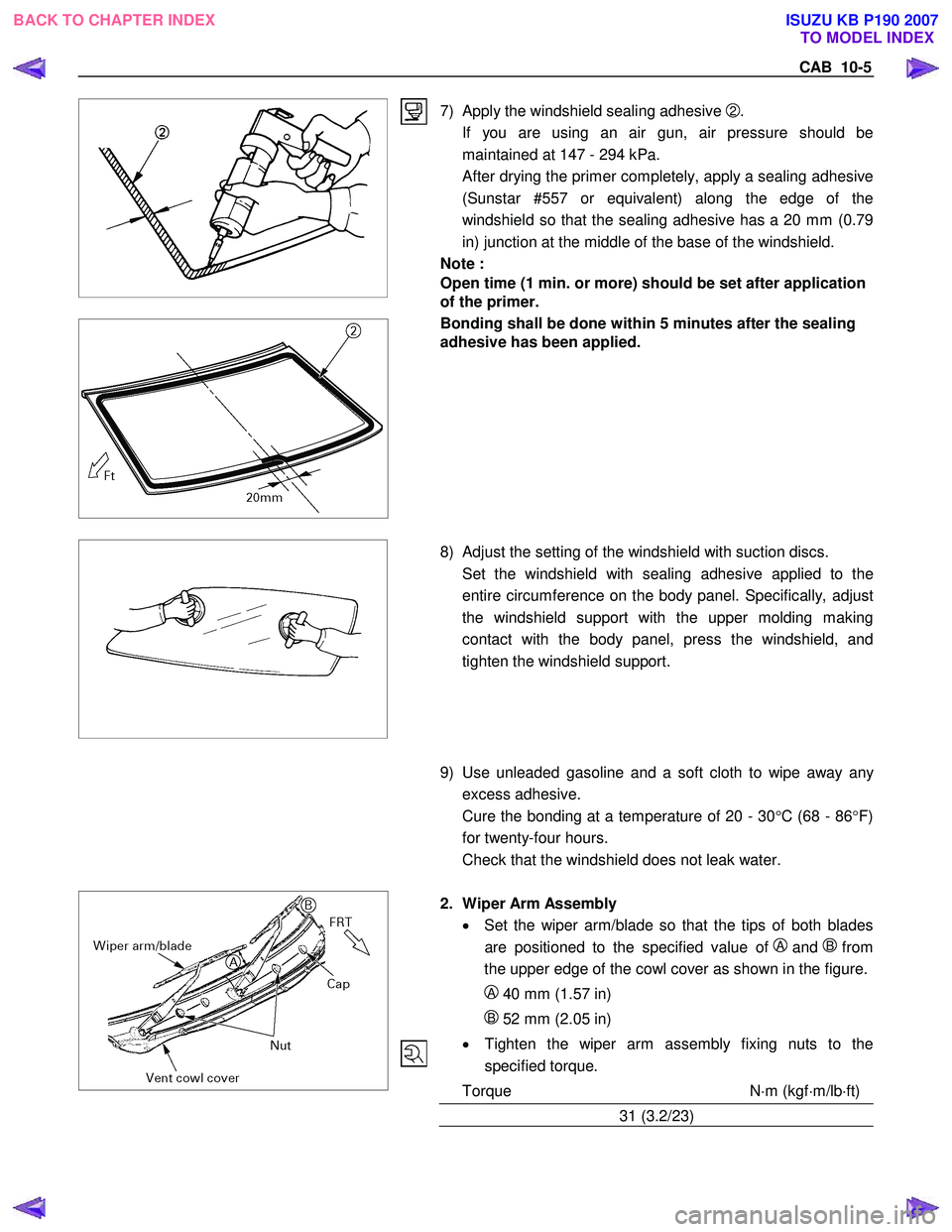
7) Apply the windshield sealing adhesive
2.
If you are using an air gun, air pressure should be maintained at 147 - 294 kPa.
After drying the primer completely, apply a sealing adhesive (Sunstar #557 or equivalent) along the edge of the
windshield so that the sealing adhesive has a 20 mm (0.79
in) junction at the middle of the base of the windshield.
Note :
Open time (1 min. or more) should be set after application
of the primer.
Bonding shall be done within 5 minutes after the sealing
adhesive has been applied.
8) Adjust the setting of the windshield with suction discs.
Set the windshield with sealing adhesive applied to the entire circumference on the body panel. Specifically, adjust
the windshield support with the upper molding making
contact with the body panel, press the windshield, and
tighten the windshield support.
9) Use unleaded gasoline and a soft cloth to wipe away any
excess adhesive.
Cure the bonding at a temperature of 20 - 30 °C (68 - 86 °F)
for twenty-four hours.
Check that the windshield does not leak water.
2. Wiper Arm Assembly
• Set the wiper arm/blade so that the tips of both blades
are positioned to the specified value of
A and Bfrom
the upper edge of the cowl cover as shown in the figure.
A 40 mm (1.57 in)
B 52 mm (2.05 in)
• Tighten the wiper arm assembly fixing nuts to the
specified torque.
Torque N ⋅m (kgf ⋅m/lb ⋅ft)
31 (3.2/23)
BACK TO CHAPTER INDEX TO MODEL INDEX
ISUZU KB P190 2007