body ISUZU KB P190 2007 Workshop Repair Manual
[x] Cancel search | Manufacturer: ISUZU, Model Year: 2007, Model line: KB P190, Model: ISUZU KB P190 2007Pages: 6020, PDF Size: 70.23 MB
Page 5569 of 6020

ELECTRICAL-BODY AND CHASSIS 8A-631
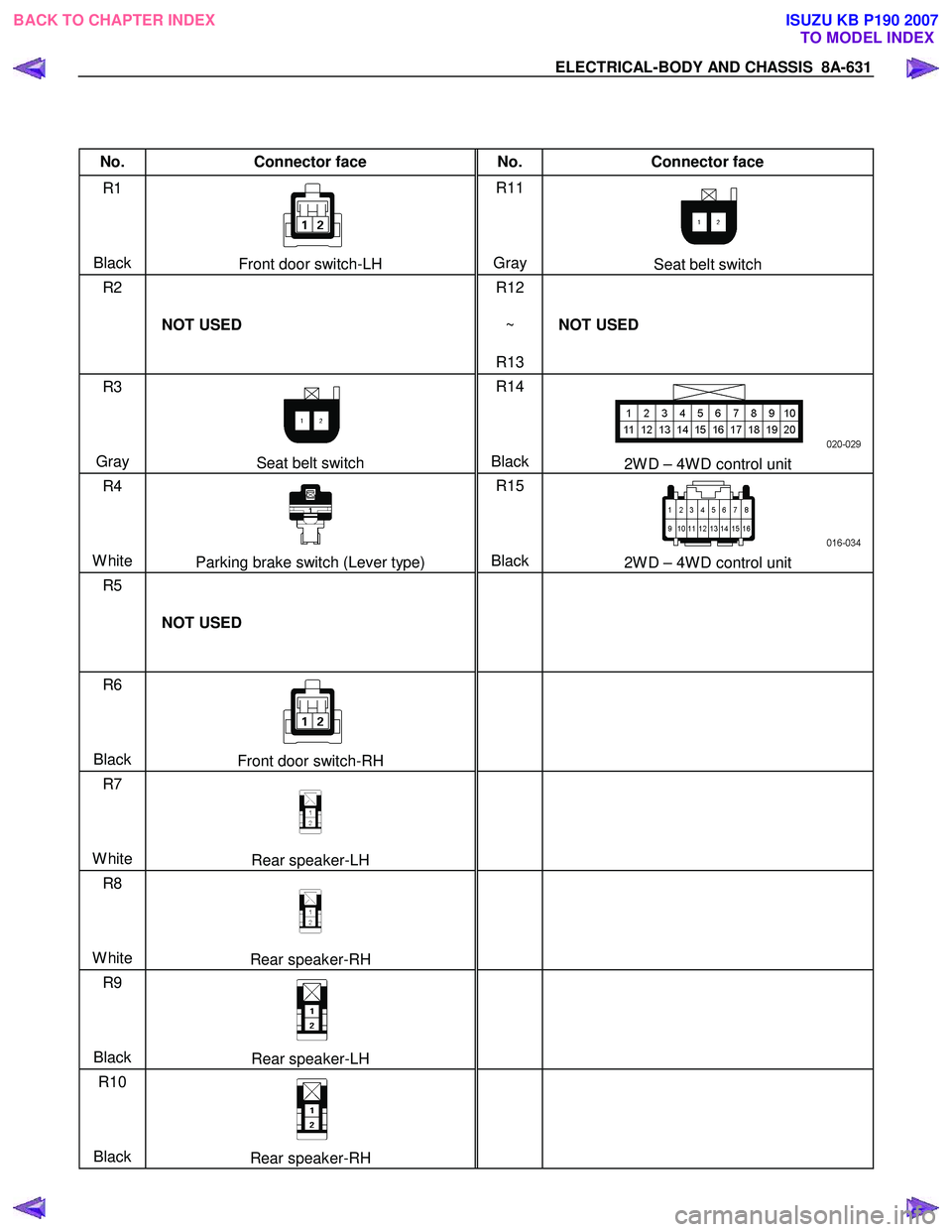
No. Connector face No. Connector face
R1
Black
Front door switch-LH R11
Gray Seat belt switch
R2
NOT USED R12
~
R13 NOT USED
R3
Gray
Seat belt switch R14
Black2W D – 4W D control unit
R4
White
Parking brake switch (Lever type) R15
Black2W D – 4W D control unit
R5
NOT USED
R6
Black
Front door switch-RH
R7
White
Rear speaker-LH
R8
White
Rear speaker-RH
R9
Black
Rear speaker-LH
R10
Black
Rear speaker-RH
BACK TO CHAPTER INDEX
TO MODEL INDEXISUZU KB P190 2007
Page 5570 of 6020

8A-632 ELECTRICAL-BODY AND CHASSIS
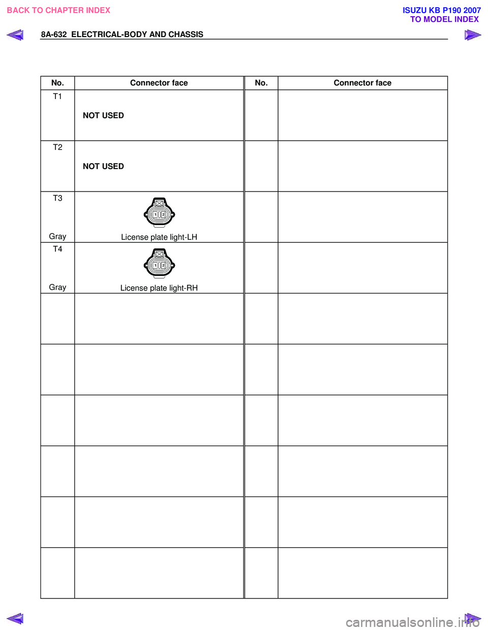
No. Connector face No. Connector face
T1
NOT USED
T2
NOT USED
T3
Gray
License plate light-LH
T4
Gray
License plate light-RH
BACK TO CHAPTER INDEX
TO MODEL INDEXISUZU KB P190 2007
Page 5571 of 6020

ELECTRICAL-BODY AND CHASSIS 8A-633
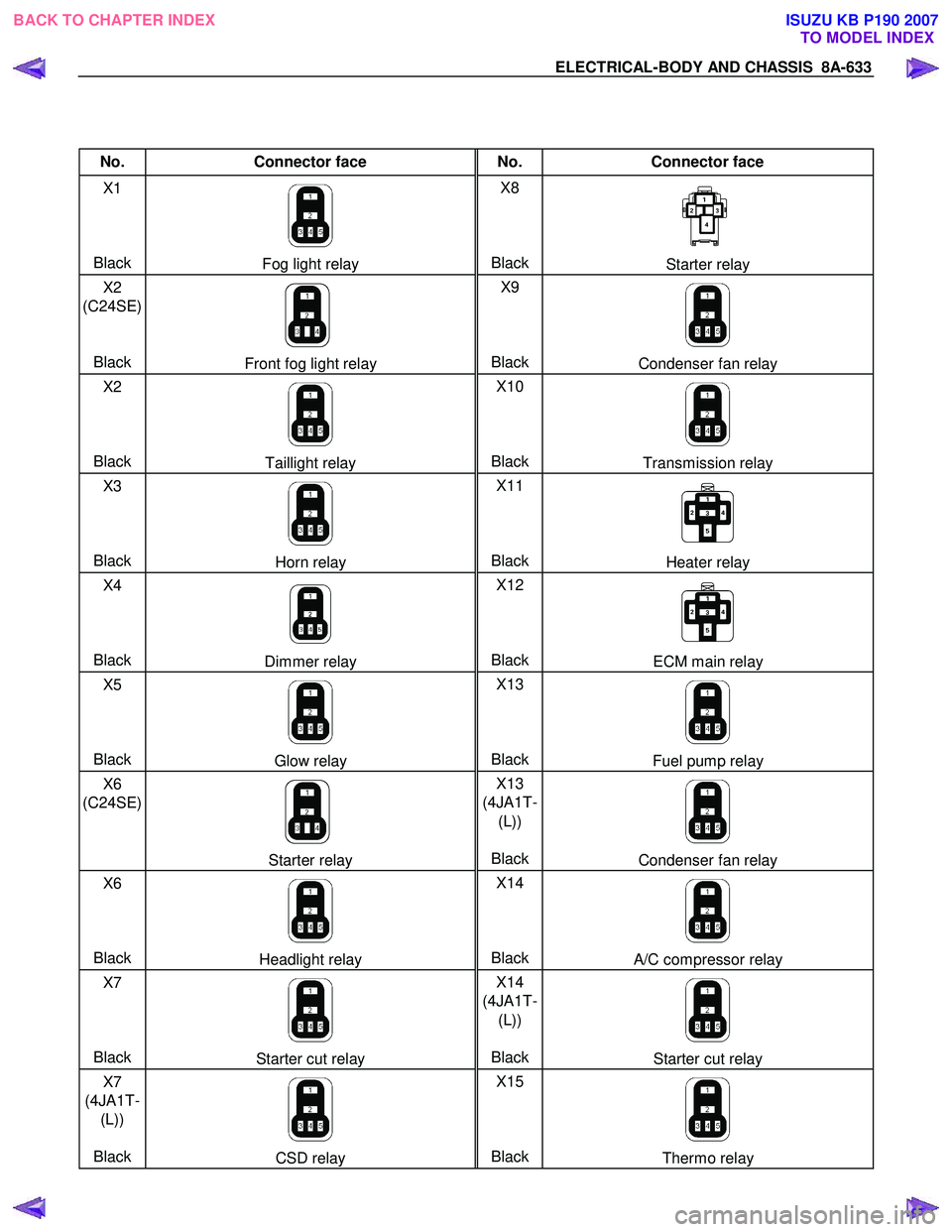
No. Connector face No. Connector face
X1
Black
Fog light relay X8
BlackStarter relay
X2
(C24SE)
Black
Front fog light relay X9
BlackCondenser fan relay
X2
Black
Taillight relay X10
BlackTransmission relay
X3
Black
Horn relay X11
BlackHeater relay
X4
Black
Dimmer relay X12
BlackECM main relay
X5
Black
Glow relay X13
BlackFuel pump relay
X6
(C24SE)
Starter relay X13
(4JA1T- (L))
BlackCondenser fan relay
X6
Black
Headlight relay X14
BlackA/C compressor relay
X7
Black
Starter cut relay X14
(4JA1T- (L))
BlackStarter cut relay
X7
(4JA1T- (L))
Black
CSD relay X15
BlackThermo relay
BACK TO CHAPTER INDEX TO MODEL INDEXISUZU KB P190 2007
Page 5572 of 6020

8A-634 ELECTRICAL-BODY AND CHASSIS
No. Connector face No. Connector face
X16
Black
DIODE
X17
Black
DIODE
BACK TO CHAPTER INDEX
TO MODEL INDEXISUZU KB P190 2007
Page 5577 of 6020

CRUISE CONTROL SYSTEM 8B-5
Adjustment
1. Check to be sure that the brake pedal has been completely
returned by the return spring.
2. Disconnect the switch connector.
RTW 780SH003301
3. Release the lock 2 by turning the switch 1 counter-clock-
wise.
4. After doing so, pull the pedal arm
3 to you a little so that
the pedal arm is not pushed in.
5. Making the pedal arm not movable with one hand, push in
the whole switch with the other hand until the plunger of the
switch is pushed in and the switch itself hits the rubber o
f
the pedal arm.
In the condition, turn the switch clock-wise until "click"
sound is made and lock it.
By doing this, the switch is adjusted at 0.2 to 1.2mm (0.01-
0.06 in) clearance.
Clutch Switch
Removal and Installation
Refer to the Clutch Control removal and installation procedure
in Clutch section.
Adjustment
1. Turn the clutch switch or stopper bolt 1 until the switch bolt
or stopper bolt just touches the clutch pedal arm.
2.
Adjust clutch switch or stopper bolt by backing it out half a
turn, and measure the clearance (L) between the clutch
pedal arm and the clutch switch bolt end or stopper bolt.
3. Lock the lock nut
2.
4. Connect the clutch switch connector.
Clutch switch and clutch pedal clearance
mm (in)
Clearance 0.5-1.5 (0.020-0.059)
Starter Switch
431R300001
Removal and Installation
Refer to the Starter Switch removal and installation procedure
of Start and Charging in Body and Chassis section.
BACK TO CHAPTER INDEX
TO MODEL INDEXISUZU KB P190 2007
Page 5578 of 6020

8B-6 CRUISE CONTROL SYSTEM
Cruise Control Main Switch
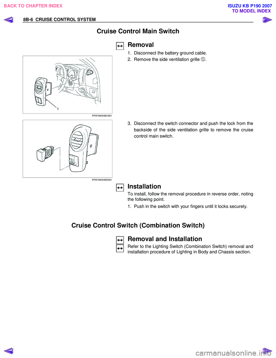
Removal
1. Disconnect the battery ground cable.
RTW 78ASH001801
2. Remove the side ventilation grille 1.
RTW 78ASH002301
3. Disconnect the switch connector and push the lock from the
backside of the side ventilation grille to remove the cruise
control main switch.
Installation
To install, follow the removal procedure in reverse order, noting
the following point.
1. Push in the switch with your fingers until it locks securely.
Cruise Control Switch (Combination Switch)
Removal and Installation
Refer to the Lighting Switch (Combination Switch) removal and
installation procedure of Lighting in Body and Chassis section.
BACK TO CHAPTER INDEX TO MODEL INDEXISUZU KB P190 2007
Page 5583 of 6020

Cruise Control – HFV6 Page 8C–5
Legend
1 Engine Control Module
2 Throttle Actuator Control (TAC) Assembly
3 Cruise Control Switch Assembly
4 Instrument Cluster Assembly 5 Cruise Control ON / OFF Switch
6 Powertrain Interface Module
7 Clutch Pedal Switch Assembly (Manual Only)
8 Stop Lamp Switch Assembly
Cruise Control Switch Assembly
The cruise control switch assembly is located on the end of
the wiper and washer switch assembly.
• For harness routing from the cruise control switch
assembly to the powertrain interface module, refer to
8A Electrical – Body and Chassis.
• For wiring and to see how the switch integrates into
the system, refer to 2.3 W iring Diagrams.
Figure 8C – 2
Instrument Cluster Assembly
The instrument cluster assembly displays the status of the cruise control system as well as other information via the
warning indicators.
Figure 8C – 3
Clutch Pedal Switch (Manual Only)
This switch assembly is attached to the clutch pedal support bracket. The switch is normally closed when the clutch
pedal is at rest, opening when the pedal is pressed. Activation of this switch removes the signal to the ECM, which will
then deactivate the cruise control.
Stop Lamp Switch Assembly
The stop lamp switch assembly is located on the brake pedal support bracket. This switch has two sets of contacts with
two independent functions. The function of the switch assembly in the cruise control system is to deactivate the cruise
control when the brake pedal is pressed as well as an initial safety check of the switch operation prior to activating cruise
control.
BACK TO CHAPTER INDEX TO MODEL INDEXISUZU KB P190 2007
Page 5584 of 6020

Cruise Control – HFV6 Page 8C–6
The stop lamp switch contacts are normally open with the brake pedal at rest and close when the brake pedal is pressed
turning on the vehicles brake lamps. These switch contacts also double as the cruise cancel signal for the cruise control
operation.
The cruise control initial brake apply signal function switch contacts are normally closed with the brake pedal at rest and
open when the brake pedal is pressed. This switch function is a safety requirement of the vehicle as it ensures that the
cruise control cannot be activated without the brake pedal first being pressed.
Powertrain Interface Module
The Powertrain Interface Module (PIM) is located on the driver’s side, kick trim panel. The purpose of the PIM is to act as
an interface between the drivetrain serial data bus (GMLAN protocol) and the body side data bus (UART Bus protocol).
All inputs from the cruise control switch assembly are directly wired to the PIM. The PIM then takes these inputs,
converts them to GMLAN protocol and sends the messages via the data bus to the engine control module (ECM). The
PIM also receives signals for the cruise control system from the ECM. When the ECM activates cruise control, it sends a
signal through the PIM (which converts it from GMLAN to UART protocol) to display the various cruise control messages
on the instrument cluster assembly.
For further information on the operation of the PIM, refer to 6E1 Powertrain Interface Module – V6.
Engine Control Module
The Engine Control Module (ECM) is mounted on the front of the engine. The role of the ECM is to receive all the inputs
from various sensors (vehicle speed (VSS) etc.) and switches to manage the engine. W hen a request is sent from the
cruise control switch assembly via the PIM to the ECM, the ECM will activate cruise control providing given parameters
are satisfied. Once the cruise is set, the ECM monitors the vehicle speed and controls the throttle actuator assembly thus
controlling the speed of the vehicle.
For further information on the operation of the ECM, refer to 6C1-1 Engine Management – V6 – General Information.
Throttle Actuator Control (TAC) Assembly
The throttle actuator control assembly is located on the front of the inlet manifold. The throttle actuator control assembly
receives signals from the ECM and controls the angle of the throttle plate. Refer to 6C1-1 Engine Management – V6 –
General Information for further information.
1.3 System Operation
Preliminary Information
Enabled and Disabled
The cruise control is enabled / disabled by pressing the cruise control ON–OFF switch mounted on the lower right hand
side of the dash panel. When cruise control is enabled, the cruise control ON–OFF switch illuminates and the cruise
control is ready for a speed to be set (cruise control activated). W hen the cruise control is disabled, the cruise control
cannot be activated.
Cruise Enabled
1 The cruise control ON–OFF switch (1) supplies 12 Volts to the Powertrain Interface Module (PIM) when it
is pressed.
2 The cruise control ON–OFF switch lamp (2) turns on.
Cruise Disabled
1 W hen cruise control ON–OFF switch (1) is pressed again, power is removed from the PIM disabling the
cruise control.
2 The cruise control ON–OFF switch lamp (2) turns off.
Figure 8C – 4
BACK TO CHAPTER INDEX TO MODEL INDEXISUZU KB P190 2007
Page 5587 of 6020

Cruise Control – HFV6 Page 8C–9
2 Diagnostics
2.1 Diagnostic General Information
Basic Knowledge Required
A lack of basic understanding regarding
electronics, electrical wiring circuits and use
of electrical circuit testing tools when
performing the cruise control diagnostic
procedures could result in incorrect
diagnostic results or damage to components.
A general understanding of basic electronics, electrical wiring circuits and the correct use of the basic electrical circuit
testing tools is required to perform the diagnostic procedures detailed in this Section. Refer to 8A Electrical – Body and
Chassis W iring Diagrams for information on electrical circuits.
In addition, a general understanding of the cruise control and its component operation is essential to prevent
misdiagnosis and component damage.
Basic Diagnostic Tools Required
Use of incorrect electrical circuit diagnostic
tools when performing the cruise control
diagnostic procedures could result in
incorrect diagnostic results or damage to
components.
The following electrical circuit testing tools are required to perform the diagnostic procedures detailed in this Section:
• test lamp,
• digital multimeter with 10 meg ohms impedance, and
• connector test adapter kit Tool No. KM609.
For further information on the use of these tools, refer to 8A Electrical – Body and Chassis W iring Diagrams.
BACK TO CHAPTER INDEX TO MODEL INDEXISUZU KB P190 2007
Page 5588 of 6020

Cruise Control – HFV6 Page 8C–10
Tech 2 Data List
The Tech 2 displays the status of certain cruise control system input parameters.
To view the data list:
1 Connect Tech 2 to the data link connector (DLC) and turn on the ignition.
2 On Tech 2 select Body / Powertrain Interface Module / Diagnostic Data Display / Data List .
Tech 2 Parameter Units Displayed Typical Display Values
Cruise Cancel Switch Inactive / Active Inactive
Cruise Resume Switch Off / Enabled Off
Cruise Set Switch Inactive / Active Inactive
Cruise Main Switch Inactive / Active Inactive
Cruise Control Set Lamp Off / On Off
Cruise Control On Lamp Off / On Off
3 On Tech 2 select Engine / V6 Engine / Data Display / Data List / Cruise Control Data.
Tech 2 Parameter Units Displayed Typical Display Values
Brake Lamp Switch Inactive / Active Inactive
Initial Brake Apply Sig Inactive / Active Inactive
Cruise Set / Decel Swit Inactive / Active Inactive
Cruise Resume / Accelerat Inactive / Active Inactive
Cruise Control Disengag Engine Speed / Brake Engine Speed
4 On Tech 2 select Engine / V6 Engine / Data Display / Data List / Engine Data 1.
Tech 2 Parameter Units Displayed Typical Display Values
Clutch Pedal Switch Inactive / Active Inactive
2.2 Diagnostic Systems Check
Diagnostic Systems Check
Refer to 2.3 Wiring Diagram to aid in the diagnosis of the cruise control system.
For the cruise control system to work effectively the following systems / components need to be serviceable:
Step Action Yes No
1 Is the fault specifically isolated to this system / module?
Go to Step 2 Go to 6E1
Powertrain Interface Module – V6
2 1 Connect Tech 2 to the DLC.
2 Ignition ON, engine OFF.
3 On Tech 2 select Body / Powertrain Interface Module / Diagnostic Trouble
codes / Read DTCs’.
Are there any set DTC’s? Go to the
appropriate DTC table in 6E1
Powertrain Interface Module – V6. Go to Step 3
BACK TO CHAPTER INDEX TO MODEL INDEXISUZU KB P190 2007