ISUZU KB P190 2007 Workshop Repair Manual
Manufacturer: ISUZU, Model Year: 2007, Model line: KB P190, Model: ISUZU KB P190 2007Pages: 6020, PDF Size: 70.23 MB
Page 2811 of 6020

Engine Mechanical – V6 Page 6A1–34
Page 6A1–34
2.4 Engine Misfire with Abnormal Internal
Lower Engine Noises
Cause Correction
Abnormalities, severe cracking, bumps or missing areas in
the accessory drive belt.
Abnormalities in the accessory drive system and/or
components may cause engine speed variations that result
in a misfire diagnostic trouble code (DTC). A misfire code
may be present without an ac tual misfire condition. Replace the accessory drive belt, refer to 3.5 Accessory
Drive Belt.
Refer to 6C1-2 Engine Management – V6 – Diagnostics to
check for DTCs
Worn, damaged or misaligned accessory drive components
and excessive pulley run-out may lead to a misfire DTC.
A misfire code may be present without an actual misfire
condition. Inspect the components and repair or replace as required.
Refer to 6C1-2 Engine Management – V6 – Diagnostics to
check for DTCs
Loose or Incorrectly fitted flexplate or crankshaft balancer
assembly.
A misfire code may be present without an actual misfire
condition. Repair or replace the flexplat
e or crankshaft balancer as
required, refer to 3.13 Crankshaft Balancer Assembly or
4.3 Flexplate Assembly.
Worn or broken piston rings.
Oil consumption may or may not cause an actual misfire. 1 Inspect the spark plugs for oil deposits, refer to 6C1-3
Engine Management – V6 – Service Operations.
2 Check the cylinders for a loss of compression, refer to 2.15 Engine Compression Test.
3 Perform compression testing to identify the cause of
low compression.
4 Repair or replace components as required.
Worn crankshaft thrust bearing.
Severely worn thrust surfaces on the crankshaft and/or
thrust bearing may permit fore and aft movement of the
crankshaft and create a DTC wi thout an actual misfire
condition being present. Replace the crankshaft and/or bear
ings as required, refer to
4.6 Crankshaft and Main Bearings.
Refer to 6C1-2 Engine Management – V6 – Diagnostics to
check for DTCs
BACK TO CHAPTER INDEX
TO MODEL INDEX
ISUZU KB P190 2007
Page 2812 of 6020
Engine Mechanical – V6 Page 6A1–35
Page 6A1–35
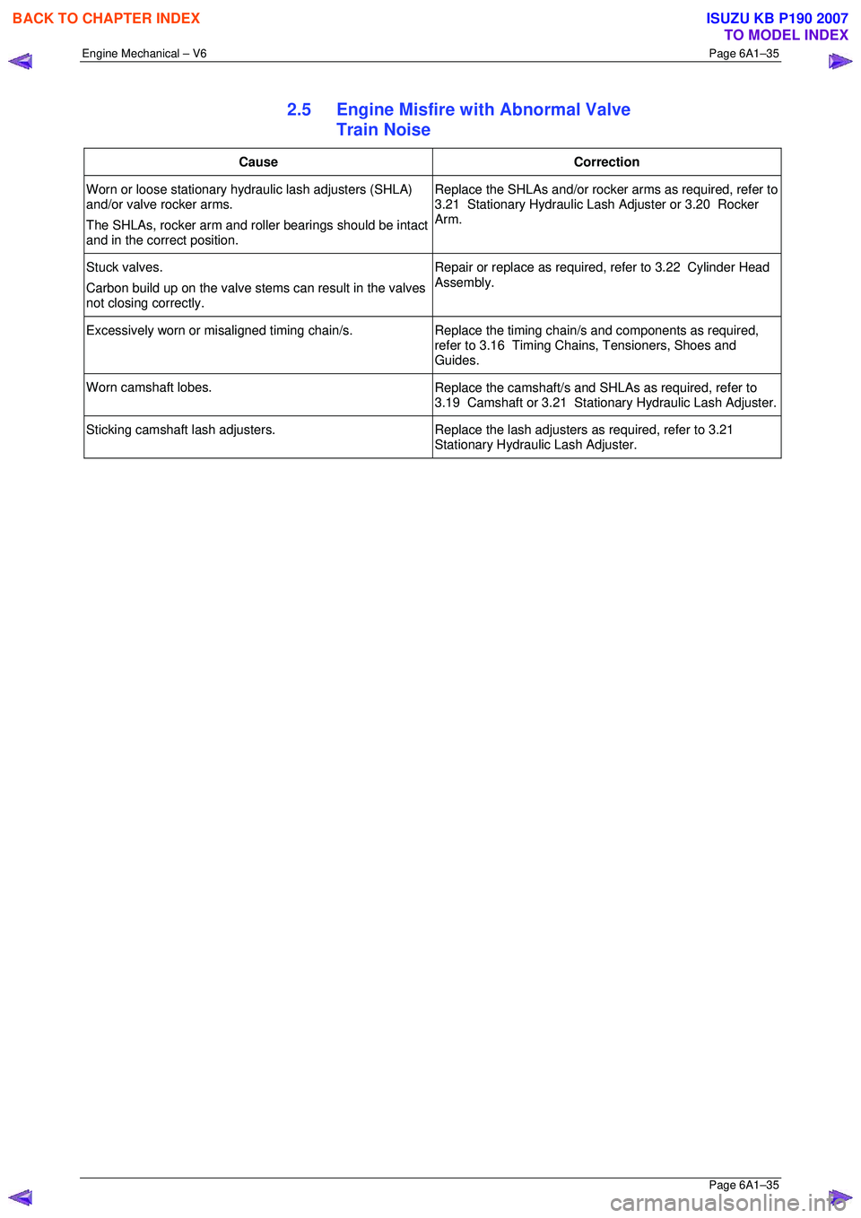
2.5 Engine Misfire with Abnormal Valve
Train Noise
Cause Correction
Worn or loose stationary hydraulic lash adjusters (SHLA)
and/or valve rocker arms.
The SHLAs, rocker arm and roller bearings should be intact
and in the correct position. Replace the SHLAs and/or rocker arms as required, refer to
3.21 Stationary Hydraulic Las h Adjuster or 3.20 Rocker
Arm.
Stuck valves.
Carbon build up on the valve stem s can result in the valves
not closing correctly. Repair or replace as required, refer to 3.22 Cylinder Head
Assembly.
Excessively worn or misaligned timing chain/s. Replace the timing chain/s and components as required,
refer to 3.16 Timing Chains, Tensioners, Shoes and
Guides.
Worn camshaft lobes. Replace the camshaft/s and SHLAs as required, refer to
3.19 Camshaft or 3.21 Stati onary Hydraulic Lash Adjuster.
Sticking camshaft lash adjusters.
Replace the lash adjusters as required, refer to 3.21
Stationary Hydraulic Lash Adjuster.
BACK TO CHAPTER INDEX
TO MODEL INDEX
ISUZU KB P190 2007
Page 2813 of 6020

Engine Mechanical – V6 Page 6A1–36
Page 6A1–36
2.6 Engine Misfire with Coolant
Consumption
Cause Correction
Faulty cylinder head gasket and/or cracking or other
damage to the cylinder heads and cylinder block coolant
passages.
Coolant consumption may or may not cause the engine to
overheat. 1 Inspect the spark plugs for
coolant saturation, refer to
6C1-3 Engine Management – V6 – Service
Operations.
2 Inspect the cylinder heads, cylinder block and/or head gaskets, refer to 3.22 Cylinder Head Assembly
and/or 4.7 Cylinder Block.
3 Repair or replace components as required.
BACK TO CHAPTER INDEX
TO MODEL INDEX
ISUZU KB P190 2007
Page 2814 of 6020

Engine Mechanical – V6 Page 6A1–37
Page 6A1–37
2.7 Engine Misfire with Excessive Oil
Consumption
Cause Correction
Worn valves, valve guides and/or valve stem oil seals. 1 Inspect the spark plugs for coolant saturation, refer to
6C1-3 Engine Management – V6 – Service
Operations.
2 Repair or replace components as required, refer to 3.22 Cylinder Head Assembly.
Worn or broken piston rings.
Oil consumption may or may not cause an actual misfire. 1 Inspect the spark plugs for oil deposits, refer to 6C1-3
Engine Management – V6 – Service Operations.
2 Check the cylinders for a loss of compression, refer to 2.15 Engine Compression Test.
3 Perform compression testing to identify the cause of
low compression.
4 Repair or replace components as required.
BACK TO CHAPTER INDEX
TO MODEL INDEX
ISUZU KB P190 2007
Page 2815 of 6020
Engine Mechanical – V6 Page 6A1–38
Page 6A1–38
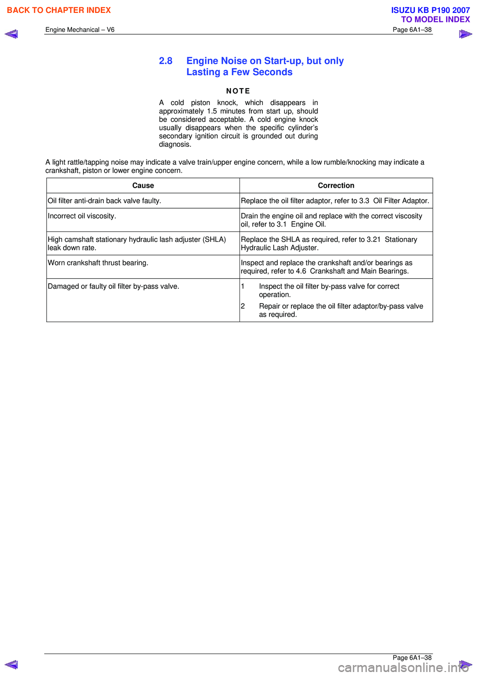
2.8 Engine Noise on Start-up, but only
Lasting a Few Seconds
NOTE
A cold piston knock, which disappears in
approximately 1.5 minutes from start up, should
be considered acceptable. A cold engine knock
usually disappears when t he specific cylinder’s
secondary ignition circuit is grounded out during
diagnosis.
A light rattle/tapping noise may indicate a valve train/upper engine concern, while a low rumble/knocking may indicate a
crankshaft, piston or lower engine concern.
Cause Correction
Oil filter anti-drain back valve faulty. Replace the o il filter adaptor, refer to 3.3 Oil Filter Adaptor.
Incorrect oil viscosity.
Drain the engine oil and replace with the correct viscosity
oil, refer to 3.1 Engine Oil.
High camshaft stationary hydraulic lash adjuster (SHLA)
leak down rate. Replace the SHLA as required,
refer to 3.21 Stationary
Hydraulic Lash Adjuster.
Worn crankshaft thrust bearing. Inspect and replace the crankshaft and/or bearings as
required, refer to 4.6 Crankshaft and Main Bearings.
Damaged or faulty oil filter by-pass valve. 1 Inspect the oil filter by-pass valve for correct
operation.
2 Repair or replace the oil filter adaptor/by-pass valve
as required.
BACK TO CHAPTER INDEX
TO MODEL INDEX
ISUZU KB P190 2007
Page 2816 of 6020
Engine Mechanical – V6 Page 6A1–39
Page 6A1–39
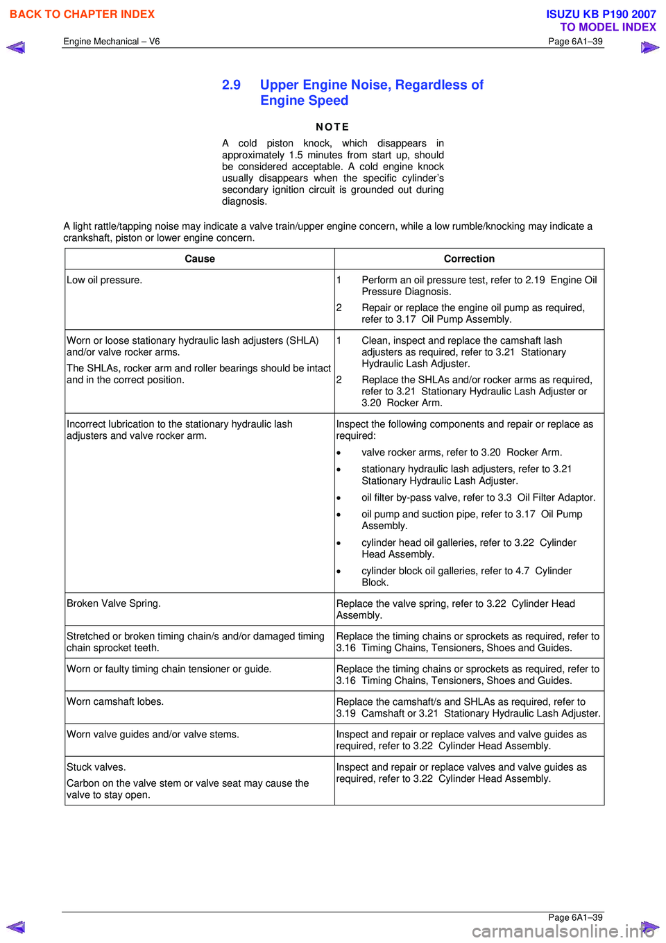
2.9 Upper Engine Noise, Regardless of
Engine Speed
NOTE
A cold piston knock, which disappears in
approximately 1.5 minutes from start up, should
be considered acceptable. A cold engine knock
usually disappears when t he specific cylinder’s
secondary ignition circuit is grounded out during
diagnosis.
A light rattle/tapping noise may indicate a valve train/upper engine concern, while a low rumble/knocking may indicate a
crankshaft, piston or lower engine concern.
Cause Correction
Low oil pressure. 1 Perform an oil pressure test, refer to 2.19 Engine Oil
Pressure Diagnosis.
2 Repair or replace the engine oil pump as required, refer to 3.17 Oil Pump Assembly.
Worn or loose stationary hydraulic lash adjusters (SHLA)
and/or valve rocker arms.
The SHLAs, rocker arm and roller bearings should be intact
and in the correct position. 1 Clean, inspect and replace the camshaft lash
adjusters as required, refer to 3.21 Stationary
Hydraulic Lash Adjuster.
2 Replace the SHLAs and/or rocker arms as required, refer to 3.21 Stationary Hydraulic Lash Adjuster or
3.20 Rocker Arm.
Incorrect lubrication to t he stationary hydraulic lash
adjusters and valve rocker arm. Inspect the following components and repair or replace as
required:
• valve rocker arms, refer to 3.20 Rocker Arm.
• stationary hydraulic lash adjusters, refer to 3.21
Stationary Hydraulic Lash Adjuster.
• oil filter by-pass valve, refe r to 3.3 Oil Filter Adaptor.
• oil pump and suction pipe, refer to 3.17 Oil Pump
Assembly.
• cylinder head oil galleries, refer to 3.22 Cylinder
Head Assembly.
• cylinder block oil galleries, refer to 4.7 Cylinder
Block.
Broken Valve Spring. Replace the valve spring, refer to 3.22 Cylinder Head
Assembly.
Stretched or broken timing chain/s and/or damaged timing
chain sprocket teeth. Replace the timing chains or sprockets as required, refer to
3.16 Timing Chains, Tensioners, Shoes and Guides.
Worn or faulty timing chain tensioner or guide. Replace the timing chains or sprockets as required, refer to
3.16 Timing Chains, Tensioners, Shoes and Guides.
Worn camshaft lobes. Replace the camshaft/s and SHLAs as required, refer to
3.19 Camshaft or 3.21 Stati onary Hydraulic Lash Adjuster.
Worn valve guides and/or valve stems.
Inspect and repair or replace valves and valve guides as
required, refer to 3.22 Cylinder Head Assembly.
Stuck valves.
Carbon on the valve stem or valve seat may cause the
valve to stay open. Inspect and repair or replace valves and valve guides as
required, refer to 3.22 Cylinder Head Assembly.
BACK TO CHAPTER INDEX
TO MODEL INDEX
ISUZU KB P190 2007
Page 2817 of 6020
Engine Mechanical – V6 Page 6A1–40
Page 6A1–40
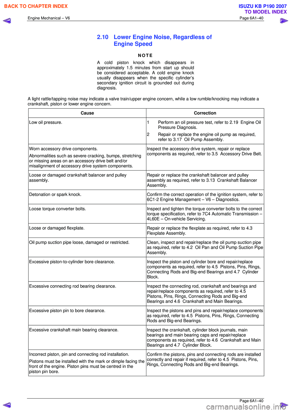
2.10 Lower Engine Noise, Regardless of
Engine Speed
NOTE
A cold piston knock which disappears in
approximately 1.5 minutes from start up should
be considered acceptable. A cold engine knock
usually disappears when t he specific cylinder’s
secondary ignition circuit is grounded out during
diagnosis.
A light rattle/tapping noise may indicate a valve train/upper engine concern, while a low rumble/knocking may indicate a
crankshaft, piston or lower engine concern.
Cause Correction
Low oil pressure. 1 Perform an oil pressure test, refer to 2.19 Engine Oil
Pressure Diagnosis.
2 Repair or replace the engine oil pump as required, refer to 3.17 Oil Pump Assembly.
Worn accessory drive components.
Abnormalities such as severe cracking, bumps, stretching
or missing areas on an accessory drive belt and/or
misalignment of accessory drive system components. Inspect the accessory drive system, repair or replace
components as required, refer to 3.5 Accessory Drive Belt.
Loose or damaged crankshaft balancer and pulley
assembly. Repair or replace the crankshaft balancer and pulley
assembly as required, refer to 3.13 Crankshaft Balancer
Assembly.
Detonation or spark knock. Confirm the correct operation of the ignition system, refer to
6C1-2 Engine Management – V6 – Diagnostics.
Loose torque converter bolts. Inspect and tighten the torque converter bolts to the correct
torque specification, refer to 7C4 Automatic Transmission –
4L60E – On-vehicle Servicing.
Loose or damaged flexplate. Repair or replace the flexplate as required, refer to 4.3
Flexplate Assembly.
Oil pump suction pipe loos e, damaged or restricted.
Clean, inspect and repair/replace the oil pump suction pipe
as required, refer to 4.2 O il Pan and Oil Pump Suction Pipe
Assembly.
Excessive piston-to-cylinder bore clearance. Inspect the piston and cylinder bore and repair/replace
components as required, refer to 4.5 Pistons, Pins, Rings,
Connecting Rods and Big-end Bearings and 4.7 Cylinder
Block.
Excessive connecting rod bearing clearance. Inspect the connecting rod, crankshaft and bearings and
repair/replace components as required, refer to 4.5
Pistons, Pins, Rings, Connecting Rods and Big-end
Bearings and 4.6 Crankshaft and Main Bearings.
Excessive piston pin to bore clearance. Inspect the pistons and pins and repair/replace components
as required, refer to 4.5 Pistons, Pins, Rings, Connecting
Rods and Big-end Bearings.
Excessive crankshaft main bearing clearance. Inspect the crankshaft, cylinder block journals, main
bearings and main bearing caps and repair/replace
components as required, refer to 4.6 Crankshaft and Main
Bearings and 4.7 Cylinder Block.
Incorrect piston, pin and c onnecting rod installation.
Pistons must be installed with the mark or dimple facing the
front of the engine. Piston pi ns must be centred in the
piston pin bore. Confirm the pistons, pins and
connecting rods are installed
correctly and repair if required, refer to 4.5 Pistons, Pins,
Rings, Connecting Rods and Big-end Bearings.
BACK TO CHAPTER INDEX
TO MODEL INDEX
ISUZU KB P190 2007
Page 2818 of 6020
Engine Mechanical – V6 Page 6A1–41
Page 6A1–41
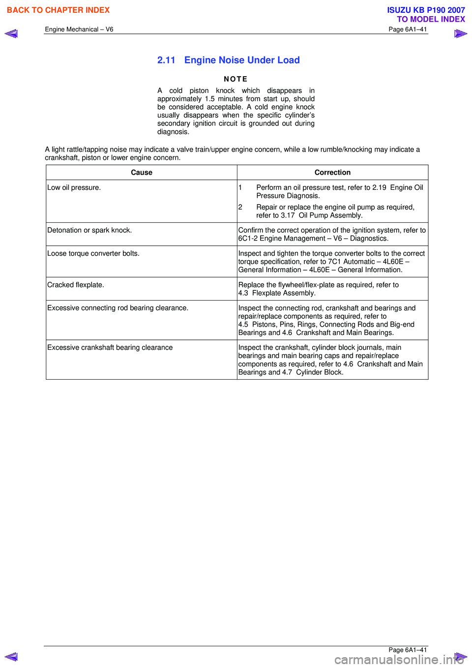
2.11 Engine Noise Under Load
NOTE
A cold piston knock which disappears in
approximately 1.5 minutes from start up, should
be considered acceptable. A cold engine knock
usually disappears when t he specific cylinder’s
secondary ignition circuit is grounded out during
diagnosis.
A light rattle/tapping noise may indicate a valve train/upper engine concern, while a low rumble/knocking may indicate a
crankshaft, piston or lower engine concern.
Cause Correction
Low oil pressure. 1 Perform an oil pressure test, refer to 2.19 Engine Oil
Pressure Diagnosis.
2 Repair or replace the engine oil pump as required, refer to 3.17 Oil Pump Assembly.
Detonation or spark knock. Confirm the correct operation of the ignition system, refer to
6C1-2 Engine Management – V6 – Diagnostics.
Loose torque converter bolts. Inspect and tighten the torque converter bolts to the correct
torque specification, refer to 7C1 Automatic – 4L60E –
General Information – 4L60E – General Information.
Cracked flexplate. Replace the flywheel/flex-plate as required, refer to
4.3 Flexplate Assembly.
Excessive connecting rod bearing clearance. Inspect the connecting rod, crankshaft and bearings and
repair/replace components as required, refer to
4.5 Pistons, Pins, Rings, Connecting Rods and Big-end
Bearings and 4.6 Crankshaft and Main Bearings.
Excessive crankshaft bearing clearance Inspect the crankshaft, cylinder block journals, main
bearings and main bearing caps and repair/replace
components as required, refer to 4.6 Crankshaft and Main
Bearings and 4.7 Cylinder Block.
BACK TO CHAPTER INDEX
TO MODEL INDEX
ISUZU KB P190 2007
Page 2819 of 6020

Engine Mechanical – V6 Page 6A1–42
Page 6A1–42
2.12 Engine Will Not Crank – Crankshaft Will
Not Rotate
Cause Correction
Seized accessory drive system component. 1 Remove the accessory drive belt, refer to
3.5 Accessory Drive Belt.
2 Rotate the crankshaft by hand at the balancer pulley or flywheel.
3 Repair or replace accessory drive system components as required.
Hydraulically locked cylinder caused by:
• coolant in cylinder,
• oil in cylinder, or
• fuel in cylinder. 1 Remove the spark plugs and check for fluid, refer to
6C1-3 Engine Management – V6 – Service
Operations.
2 Inspect for broken head gasket/s.
3 Inspect for cracked engine block or cylinder head.
4 Inspect for sticking fuel injector.
5 Repair or replace components as required.
Seized torque converter. 1 Remove the torque converter bolts, refer to 7C1
Automatic – 4L60E – General Information – 4L60E –
General Information.
2 Rotate the crankshaft by hand at the balancer pulley or flywheel.
3 Repair or replace torque converter as required.
Material in cylinder bore, caused by:
• broken valve,
• broken piston or ring, or
• dirt or foreign matter entry during engine assembly
procedure. 1 Clean and inspect the cylinder for damaged
components and or foreign matter, refer to 4.7
Cylinder Block.
2 Repair or replace components as required.
Seized crankshaft or connecting rod bearings. Inspect and repair or replace crankshaft, connecting rod
and bearings as required, refer to 4.5 Pistons, Pins, Rings,
Connecting Rods and Big-end Bearings and 4.6
Crankshaft and Main Bearings.
Bent or broken connecting rod. Inspect and repair or replace connecting rod and bearings
as required, refer to 4.5 Pistons, Pins, Rings, Connecting
Rods and Big-end Bearings.
Bent or broken crankshaft. Inspect and repair or replace crankshaft and bearings as
required, refer to 4.6 Crankshaft and Main Bearings.
Seized or broken camshaft. 1 Inspect and replace camshafts as required, refer to
3.19 Camshaft.
2 Inspect camshaft journals and cam caps on cylinder head and repair or replace components as required,
refer to 3.22 Cylinder Head Assembly.
Seized or broken camshaft timing components. 1 Inspect the crankshaft, idler, intake camshaft and
exhaust camshaft sprockets.
2 Inspect the timing chains.
3 Inspect the guides.
4 Inspect the tensioners.
5 Repair or replace components as required, refer to 3.16 Timing Chains, Tensioners, Shoes and Guides.
Seized or broken valve train components. 1 Inspect the stationary hydraulic lash adjusters, refer
to 3.21 Stationary Hydraulic Lash Adjuster.
2 Inspect the rocker arms, re fer to 3.20 Rocker Arm.
3 Inspect the Valves Refer to 3.22 Cylinder Head Assembly.
4 Inspect the valve springs, refer to 3.22 Cylinder Head Assembly.
5 Repair or replace components as required.
BACK TO CHAPTER INDEX
TO MODEL INDEX
ISUZU KB P190 2007
Page 2820 of 6020

Engine Mechanical – V6 Page 6A1–43
Page 6A1–43
2.13 Coolant in Combustion Chamber
Definition
Excessive white smoke and/or coolant type odour emitted from the exhaust pipe may indicate coolant in the combustion
chamber. Low coolant levels, an inoperativ e engine cooling fan or a faulty thermostat may lead to an over-temperature
condition which may cause internal engine component damage. A slower than normal cranking speed may indicate
coolant entering the combustion chamber.
1 Remove the spark plugs and inspect for spark plugs sa turated by coolant and coolant in the cylinder bore.
2 Inspect by performing a cylinder leakage test, refer to 2.16 Cylinder Leakage Test. During this test, excessive air
bubbles in the coolant may indicate a faulty head ga sket, cracked cylinder head or cracked cylinder block.
3 Inspect by performing a cylinder compression test. Two cylinders side-by-side on the cylinder block, with low
compression, may indicate a fa iled cylinder head gasket, refer to 2.15 Engine Compression Test.
Cause Correction
Cracked intake manifold or faulty gasket. Replace components as required, refer to 3.10 Intake
Manifold Assembly – Complete.
Faulty cylinder head gasket. Replace the cylinder head gasket, refer to 3.22 Cylinder
Head Assembly.
Warped cylinder head. Repair or replace the cylinder heads as required, refer to
3.22 Cylinder Head Assembly.
Cracked cylinder liner or block Repair or replace the cylinder block and components as
required, refer to 4.7 Cylinder Block.
Cylinder head or cylinder block porosity. Repair or replace the cylinder block or cylinder heads as
required, refer to 4.7 Cylinder Block or 3.22 Cylinder Head
Assembly.
BACK TO CHAPTER INDEX
TO MODEL INDEX
ISUZU KB P190 2007