ISUZU KB P190 2007 Workshop Repair Manual
Manufacturer: ISUZU, Model Year: 2007, Model line: KB P190, Model: ISUZU KB P190 2007Pages: 6020, PDF Size: 70.23 MB
Page 2851 of 6020
Engine Mechanical – V6 Page 6A1–74
Page 6A1–74
3.6 Accessory Drive Belt Idler Pulley
Remove
1 Remove the accessory drive belt, refer to 3.5 Accessory Drive Belt.
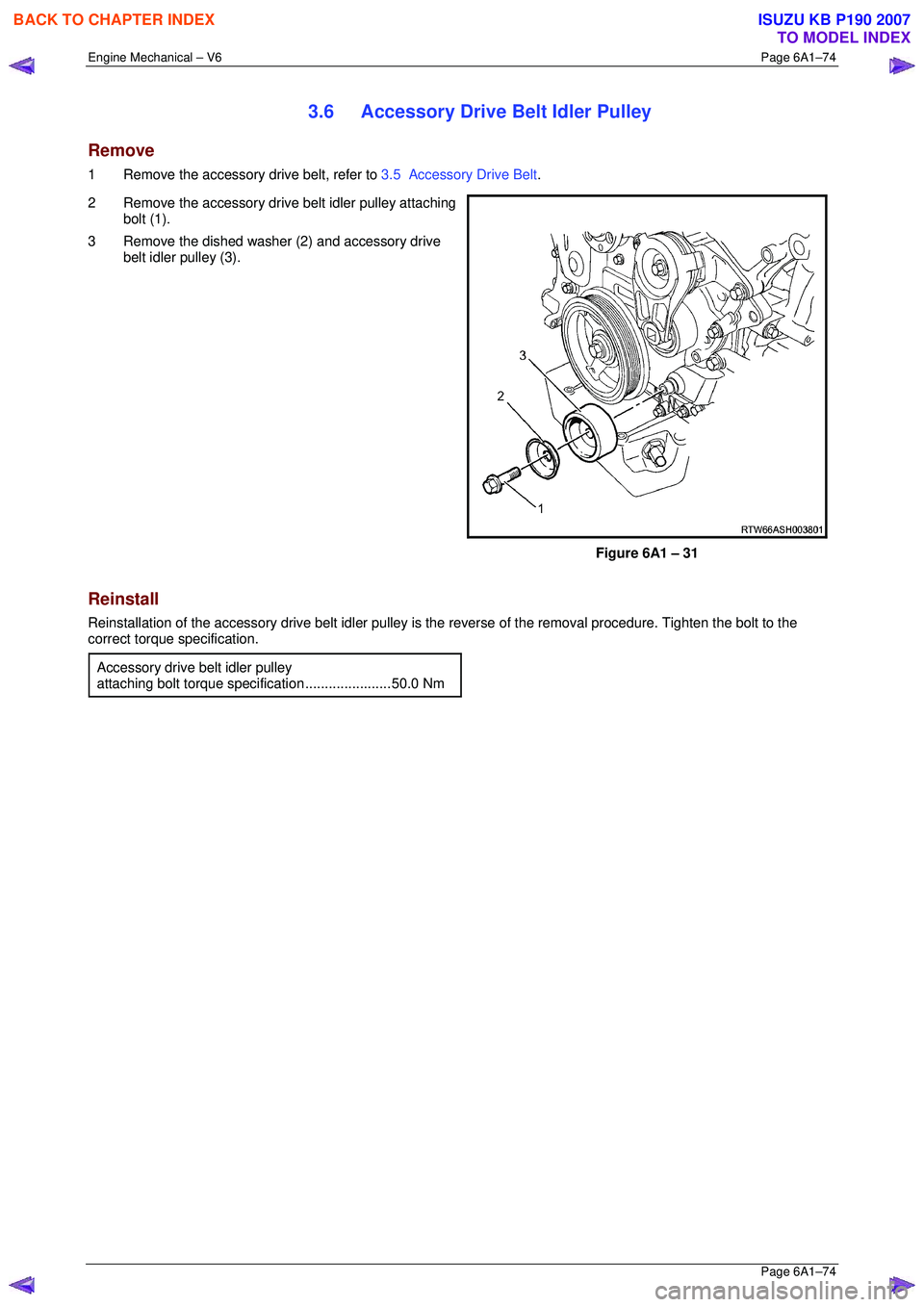
2 Remove the accessory drive belt idler pulley attaching bolt (1).
3 Remove the dished washer (2) and accessory drive belt idler pulley (3).
Figure 6A1 – 31
Reinstall
Reinstallation of the accessory drive belt idler pulley is t he reverse of the removal procedure. Tighten the bolt to the
correct torque specification.
Accessory drive belt idler pulley
attaching bolt torque specification ......................50.0 Nm
BACK TO CHAPTER INDEX
TO MODEL INDEX
ISUZU KB P190 2007
Page 2852 of 6020
Engine Mechanical – V6 Page 6A1–75
Page 6A1–75
3.7 Accessory Drive Belt Tensioner
Assembly
Remove
1 Remove the accessory drive belt, refer to 3.5 Accessory Drive Belt.
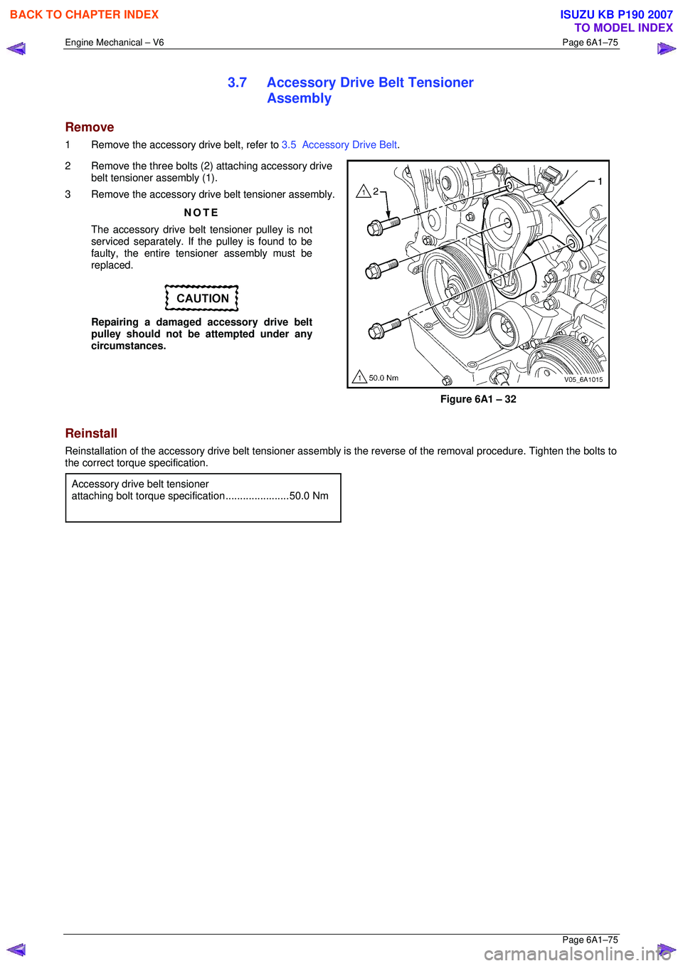
2 Remove the three bolts (2) attaching accessory drive belt tensioner assembly (1).
3 Remove the accessory drive belt tensioner assembly.
NOTE
The accessory drive belt tensioner pulley is not
serviced separately. If the pulley is found to be
faulty, the entire tensi oner assembly must be
replaced.
Repairing a damaged accessory drive belt
pulley should not be attempted under any
circumstances.
Figure 6A1 – 32
Reinstall
Reinstallation of the accessory drive belt tensioner assembly is the reverse of the removal procedure. Tighten the bolts to
the correct torque specification.
Accessory drive belt tensioner
attaching bolt torque specification ......................50.0 Nm
BACK TO CHAPTER INDEX
TO MODEL INDEX
ISUZU KB P190 2007
Page 2853 of 6020
Engine Mechanical – V6 Page 6A1–76
Page 6A1–76
3.8 Power Steering Pump Bracket
Remove
1 Remove the power steering pump and reservoir, refer to Section 3B Steering.
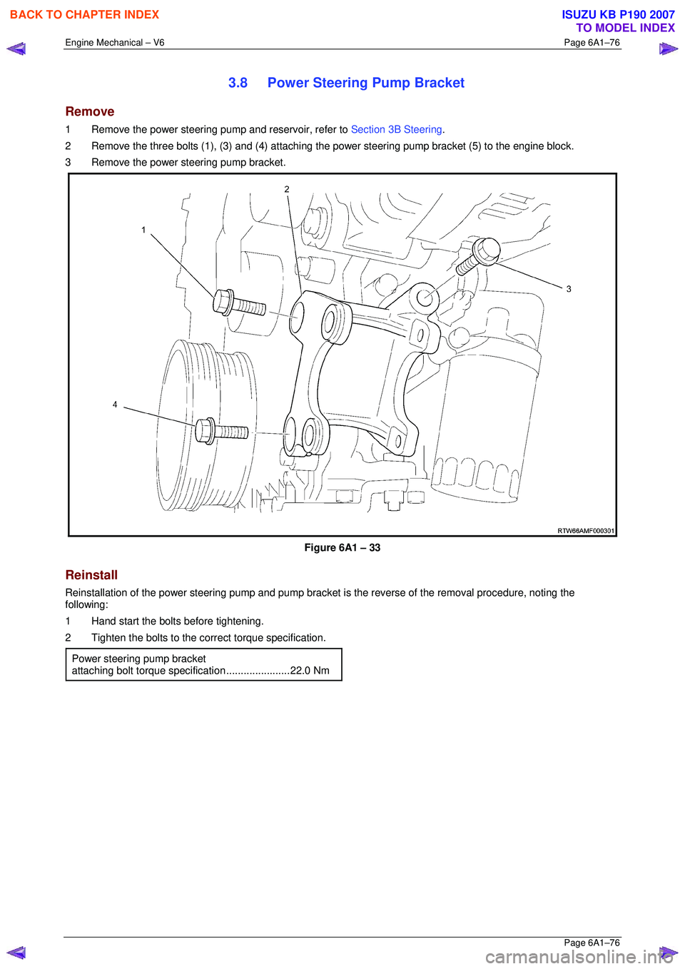
2 Remove the three bolts (1), (3) and (4) attaching t he power steering pump bracket (5) to the engine block.
3 Remove the power steering pump bracket.
Figure 6A1 – 33
Reinstall
Reinstallation of the power steering pump and pump bracket is the reverse of the removal procedure, noting the
following:
1 Hand start the bolts before tightening.
2 Tighten the bolts to the co rrect torque specification.
Power steering pump bracket
attaching bolt torque specification ......................22.0 Nm
BACK TO CHAPTER INDEX
TO MODEL INDEX
ISUZU KB P190 2007
Page 2854 of 6020
Engine Mechanical – V6 Page 6A1–77
Page 6A1–77
3.9 Upper Intake Manifold
The intake manifold comprises of an upper and lower section. Some service procedures only require the removal of the
upper intake manifold (e.g. fuel injector/spark plug servicing), while other servic e procedures require the removal of both
the upper and lower manifold as a complete assembly (e .g. cylinder head/s). If the complete assembly needs to be
removed, refer to 3.10 Intake Manifold Assembly – Complete .
Remove
Disconnection of the battery affects
certain vehicle electronic systems. Refer to
1.1 WARNING, CAUTION and NOTES before
disconnecting the battery.
1 Disconnect the battery negative terminal.
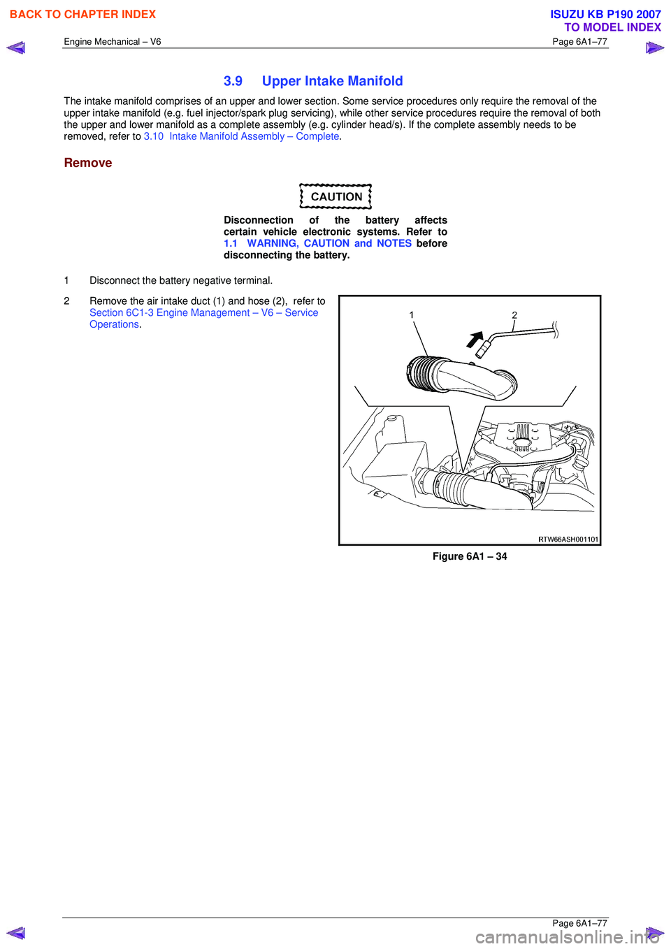
2 Remove the air intake duct (1) and hose (2), refer to
Section 6C1-3 Engine Management – V6 – Service
Operations .
Figure 6A1 – 34
BACK TO CHAPTER INDEX
TO MODEL INDEX
ISUZU KB P190 2007
Page 2855 of 6020
Engine Mechanical – V6 Page 6A1–78
Page 6A1–78
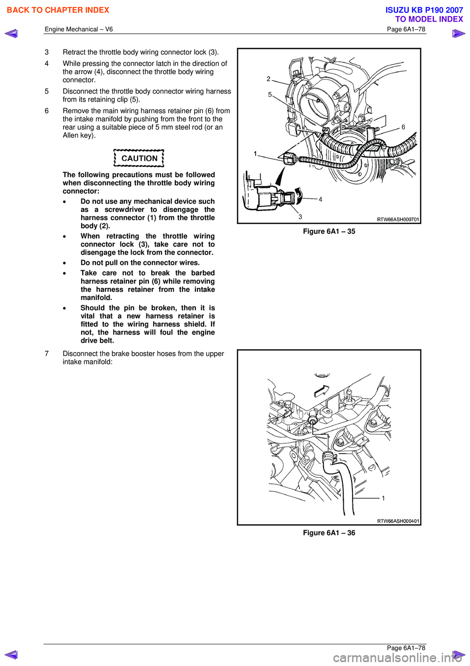
3 Retract the throttle body wiring connector lock (3).
4 While pressing the connector latch in the direction of
the arrow (4), disconnect the throttle body wiring
connector.
5 Disconnect the throttle body connector wiring harness from its retaining clip (5).
6 Remove the main wiring harness retainer pin (6) from the intake manifold by pushing from the front to the
rear using a suitable piece of 5 mm steel rod (or an
Allen key).
The following precautions must be followed
when disconnecting the throttle body wiring
connector:
• Do not use any mechanical device such
as a screwdriver to disengage the
harness connector (1) from the throttle
body (2).
• When retracting the throttle wiring
connector lock (3), take care not to
disengage the lock from the connector.
• Do not pull on the connector wires.
• Take care not to break the barbed
harness retainer pin (6) while removing
the harness retainer from the intake
manifold.
• Should the pin be broken, then it is
vital that a new harness retainer is
fitted to the wiring harness shield. If
not, the harness will foul the engine
drive belt.
Figure 6A1 – 35
7 Disconnect the brake booster hoses from the upper intake manifold:
Figure 6A1 – 36
BACK TO CHAPTER INDEX
TO MODEL INDEX
ISUZU KB P190 2007
Page 2856 of 6020

Engine Mechanical – V6 Page 6A1–79
Page 6A1–79
8 Disconnect the wiring harness connector from the
barometric (BARO) pressure sensor (1).
Figure 6A1 – 37
9 Disconnect the PCV tube connector (1) from the upper intake manifold assembly.
Figure 6A1 – 38
10 Remove the bolt (3) attaching the EVAP valve and the fuel injector wiring harness connector mounting
bracket to the upper inta ke manifold assembly.
11 Move the EVAP valve and the fuel injector wiring harness connector mounting br acket clear of the upper
intake manifold assembly.
12 Disconnect the PCV fresh air tube (1) from its upper intake manifold mounting clip (2).
Figure 6A1 – 39
BACK TO CHAPTER INDEX
TO MODEL INDEX
ISUZU KB P190 2007
Page 2857 of 6020

Engine Mechanical – V6 Page 6A1–80
Page 6A1–80
13 Disconnect the EVAP valve outlet tube (1) from the
intake manifold (2).
14 Remove the four long (3) (165 mm long) and two short bolts (4) (70 mm long) attaching the upper intake
manifold (2) to the cylinder heads and lower intake
manifold.
15 Lift the upper intake manifold (2) clear from the lower half and then remove the upper intake manifold from
the engine.
16 Remove and discard the upper to lower intake manifold gaskets (5).
• When the upper intake manifold is
removed, plug each of the lower intake
runner openings with lint free cloth, to
stop the entry of forei gn material into the
engine.
• Do not reuse the upper to lower intake
manifold gaskets (5).
Figure 6A1 – 40
17 Remove the upper and lower intake manifold assembly from the engine.
18 Remove lower intake mani fold to cylinder head gasket.
Disassemble
Remove the following from the upper intake manifold, refer to Section 6C1-3 Engine Management – V6 – Service
Operations :
• BARO sensor and
• Throttle body assembly.
Clean
CAUTION
Due to the aluminium alloy construction of
the intake manifold, wire brushes and steel
scrapers must not be used during the
cleaning process, as damage to sealing
surfaces may occur. Use of a wooden or
plastic scraper is preferred.
1 Clean mating surfaces ensuring any gasket material is removed.
2 Clean the manifold using a suitable solvent.
Safety glasses must be worn when using
compressed air.
3 Dry the timing components with compressed air.
BACK TO CHAPTER INDEX
TO MODEL INDEX
ISUZU KB P190 2007
Page 2858 of 6020
Engine Mechanical – V6 Page 6A1–81
Page 6A1–81
Inspect
1 Inspect the intake manifold for the following fault conditions:
• Damaged sealing and mating surfaces.
• Damaged lower intake manifold gasket.
• Damage or excessive debris on the threaded and through holes.
• Cracks or damage to the intake manifold body.
NOTE
If the lower intake manifold is cracked or
damaged, it must be repl aced. No welding or
patching of the intake manifold should be
performed.
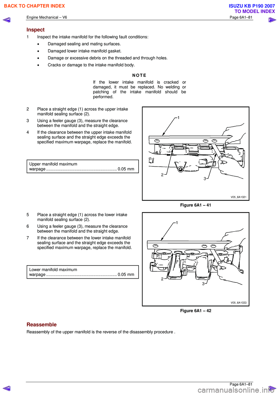
2 Place a straight edge (1) across the upper intake manifold sealing surface (2).
3 Using a feeler gauge (3), measure the clearance
between the manifold and the straight edge.
4 If the clearance between the upper intake manifold sealing surface and the straight edge exceeds the
specified maximum warpage, replace the manifold.
Upper manifold maximum
warpage ............................................................ 0.05 mm
Figure 6A1 – 41
5 Place a straight edge (1) across the lower intake manifold sealing surface (2).
6 Using a feeler gauge (3), measure the clearance
between the manifold and the straight edge.
7 If the clearance between the lower intake manifold sealing surface and the straight edge exceeds the
specified maximum warpage, replace the manifold.
Lower manifold maximum
warpage ............................................................ 0.05 mm
Figure 6A1 – 42
Reassemble
Reassembly of the upper manifold is the reverse of the disassembly procedure .
BACK TO CHAPTER INDEX
TO MODEL INDEX
ISUZU KB P190 2007
Page 2859 of 6020
Engine Mechanical – V6 Page 6A1–82
Page 6A1–82
Reinstall
Reinstallation of the upper intake manifold and the upper and lower intake manifold assembly is the reverse of the
removal procedure, noting the following:
1 Only new gaskets are to be fitted betw een the upper and lower intake manifolds.
CAUTION
Tighten the intake manifold bolts in a circular
pattern starting at the centre bolt and moving
outward.
2 Ensure that all fasteners are tightened to the correct torque specification.
Upper intake manifold to lower
intake manifold attaching bolt
torque specificat ion ............................................ 23.0 Nm
Upper intake manifold to
cylinder head attaching bolt
torque specification ............................................ 23.0 Nm
Incorrect wiring connector installation may
cause component malfunction or component
damage.
3 Ensure all wiring connectors are fully engaged and if applicable, locked in place.
4 Ensure all wiring harnesses are correctly routed and attached securely in their retaining clips.
5 Ensure that all hoses and pipes ar e routed correctly and that any retaining clips are correctly installed.
6 Start and run the engine to c heck for correct operation.
BACK TO CHAPTER INDEX
TO MODEL INDEX
ISUZU KB P190 2007
Page 2860 of 6020
Engine Mechanical – V6 Page 6A1–83
Page 6A1–83
3.10 Intake Manifold Assembly – Complete
The intake manifold comprises of an upper and lower section. Some service procedures only require the removal of the
upper intake manifold (e.g. fuel injector/spark plug servicing), while other servic e procedures require the removal of both
the upper and lower manifold as a complete assembly (e.g . cylinder head/s). If only the upper intake manifold needs to
be removed, refer to 3.9 Upper Intake Manifold .
Remove
Disconnection of the battery affects
certain vehicle electronic systems. Refer to
1.1 WARNING, CAUTION and NOTES before
disconnecting the battery.
1 Depressurise the fuel system.
2 Disconnect the battery negative terminal.
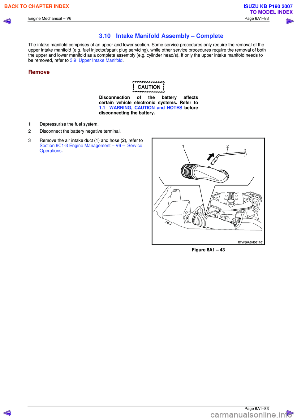
3 Remove the air intake duc t (1) and hose (2), refer to
Section 6C1-3 Engine Management – V6 – Service
Operations .
Figure 6A1 – 43
BACK TO CHAPTER INDEX
TO MODEL INDEX
ISUZU KB P190 2007