lock ISUZU KB P190 2007 Workshop Repair Manual
[x] Cancel search | Manufacturer: ISUZU, Model Year: 2007, Model line: KB P190, Model: ISUZU KB P190 2007Pages: 6020, PDF Size: 70.23 MB
Page 2741 of 6020
Engine Mechanical – V6 Page 6A1–262
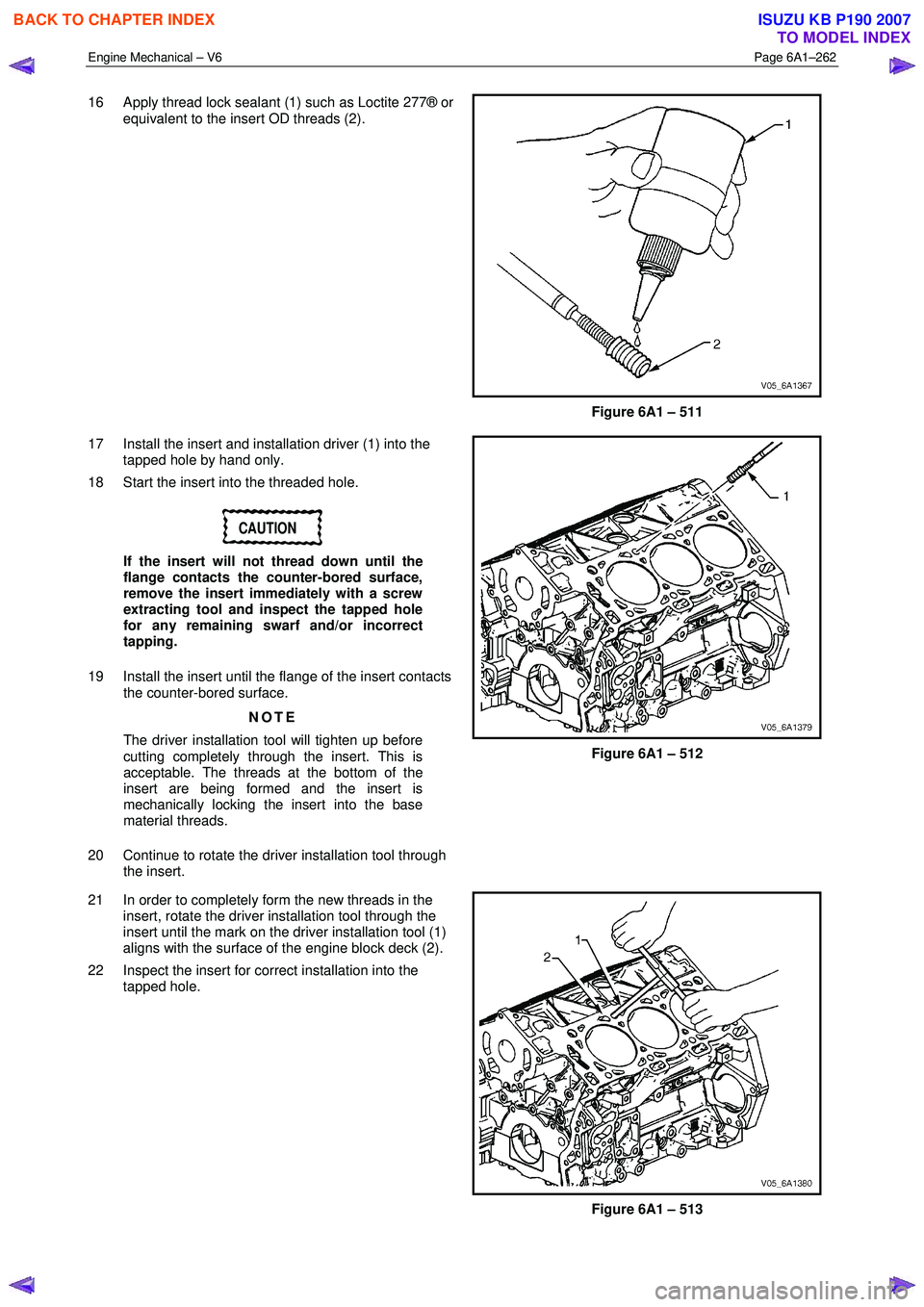
16 Apply thread lock sealant (1) such as Loctite 277® or
equivalent to the insert OD threads (2).
Figure 6A1 – 511
17 Install the insert and installation driver (1) into the tapped hole by hand only.
18 Start the insert into the threaded hole.
CAUTION
If the insert will not thread down until the
flange contacts the counter-bored surface,
remove the insert immediately with a screw
extracting tool and inspect the tapped hole
for any remaining swarf and/or incorrect
tapping.
19 Install the insert until the flange of the insert contacts the counter-bored surface.
NOTE
The driver installation tool will tighten up before
cutting completely through the insert. This is
acceptable. The threads at the bottom of the
insert are being formed and the insert is
mechanically locking the insert into the base
material threads.
20 Continue to rotate the driver installation tool through the insert.
Figure 6A1 – 512
21 In order to completely form the new threads in the insert, rotate the driver installation tool through the
insert until the mark on the driver installation tool (1)
aligns with the surface of the engine block deck (2).
22 Inspect the insert for correct installation into the tapped hole.
Figure 6A1 – 513
BACK TO CHAPTER INDEX
TO MODEL INDEX
ISUZU KB P190 2007
Page 2752 of 6020
Engine Mechanical – V6 Page 6A1–273
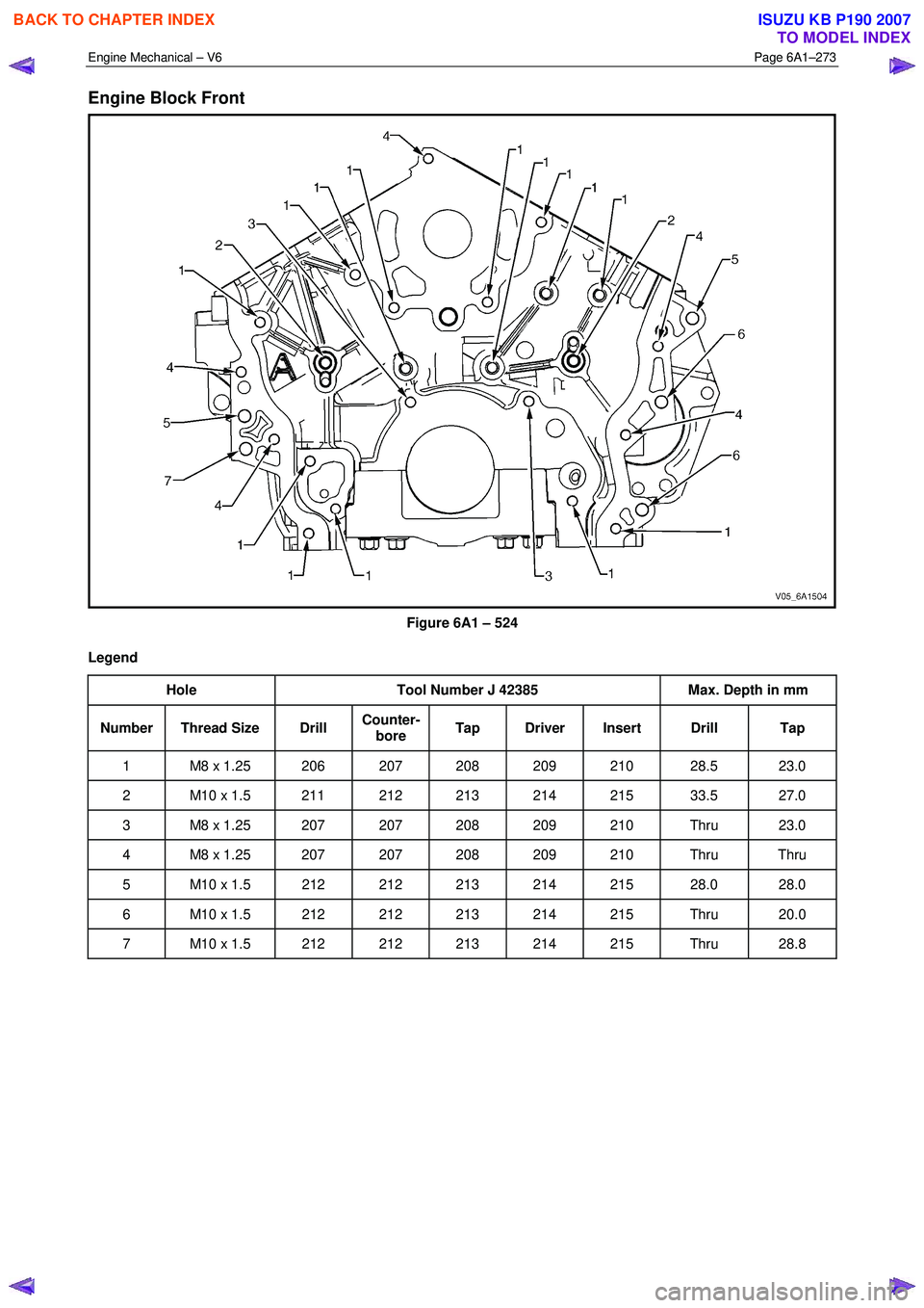
Engine Block Front
Figure 6A1 – 524
Legend Hole Tool Number J 42385 Max. Depth in mm
Number Thread Size Drill Counter-
bore Tap Driver Insert Drill Tap
1 M8 x 1.25 206 207 208 209 210 28.5 23.0
2 M10 x 1.5 211 212 213 214 215 33.5 27.0
3 M8 x 1.25 207 207 208 209 210 Thru 23.0
4 M8 x 1.25 207 207 208 209 210 Thru Thru
5 M10 x 1.5 212 212 213 214 215 28.0 28.0
6 M10 x 1.5 212 212 213 214 215 Thru 20.0
7 M10 x 1.5 212 212 213 214 215 Thru 28.8
BACK TO CHAPTER INDEX
TO MODEL INDEX
ISUZU KB P190 2007
Page 2753 of 6020
Engine Mechanical – V6 Page 6A1–274
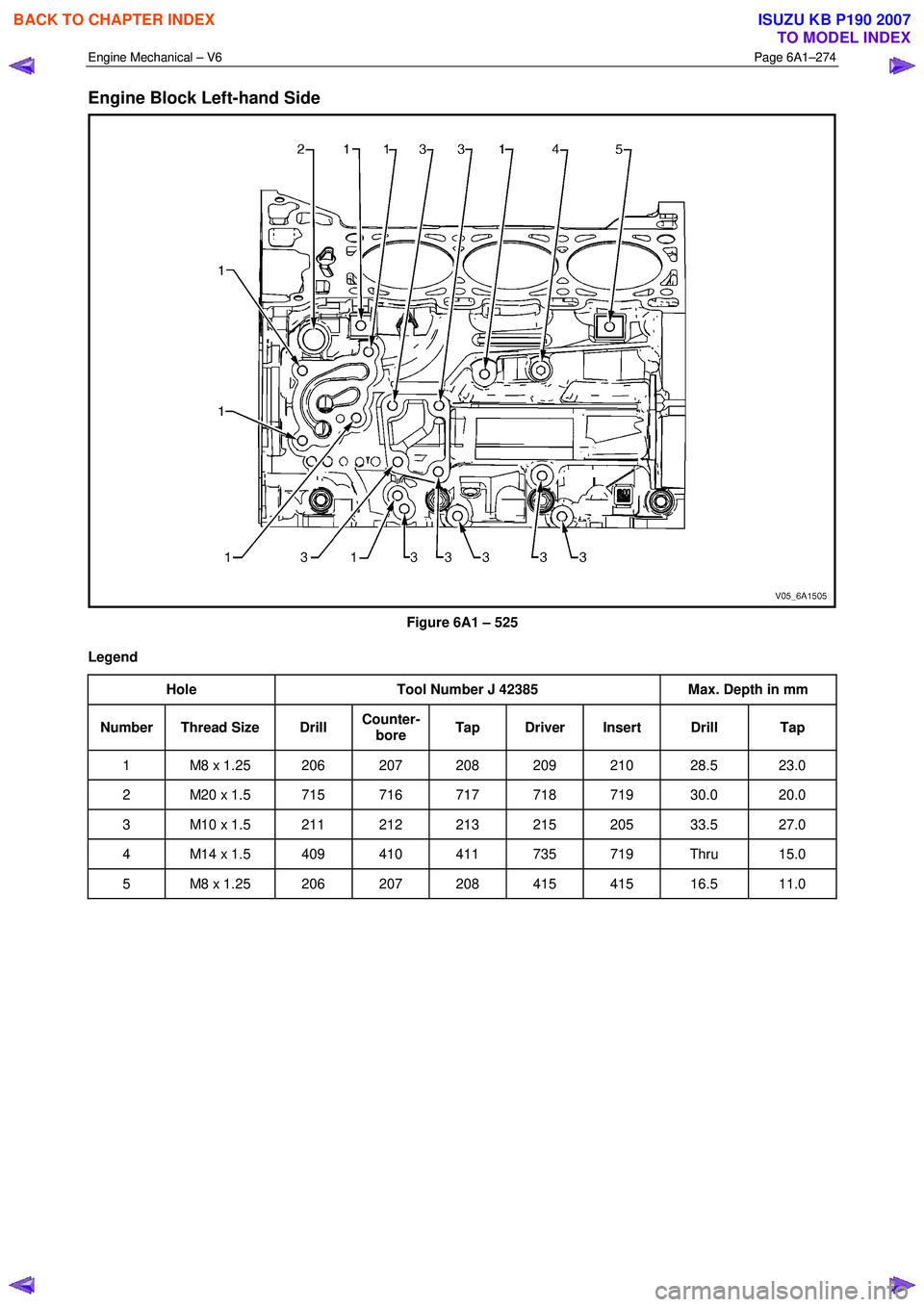
Engine Block Left-hand Side
Figure 6A1 – 525
Legend Hole Tool Number J 42385 Max. Depth in mm
Number Thread Size Drill Counter-
bore Tap Driver Insert Drill Tap
1 M8 x 1.25 206 207 208 209 210 28.5 23.0
2 M20 x 1.5 715 716 717 718 719 30.0 20.0
3 M10 x 1.5 211 212 213 215 205 33.5 27.0
4 M14 x 1.5 409 410 411 735 719 Thru 15.0
5 M8 x 1.25 206 207 208 415 415 16.5 11.0
BACK TO CHAPTER INDEX
TO MODEL INDEX
ISUZU KB P190 2007
Page 2754 of 6020
Engine Mechanical – V6 Page 6A1–275
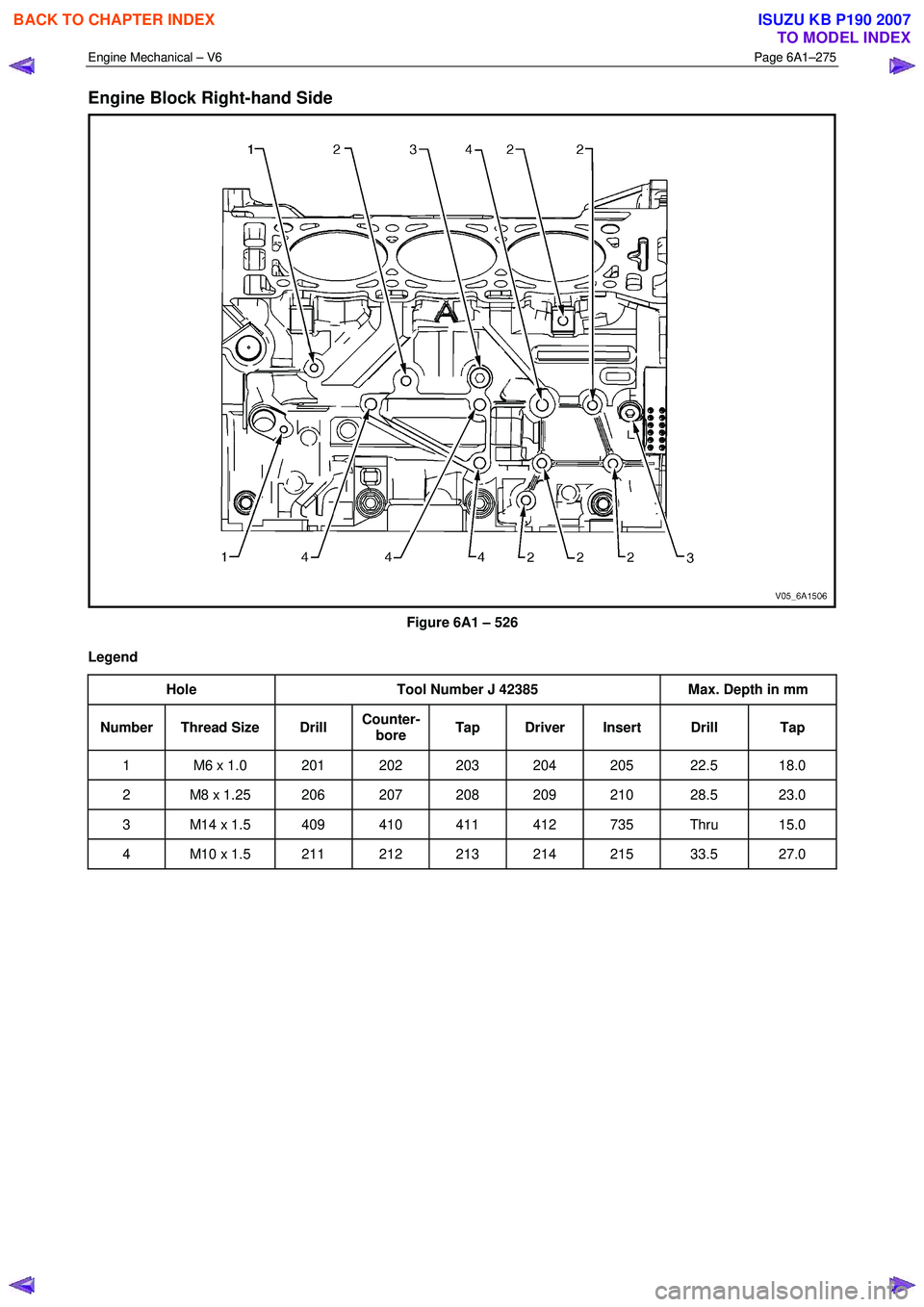
Engine Block Right-hand Side
Figure 6A1 – 526
Legend Hole Tool Number J 42385 Max. Depth in mm
Number Thread Size Drill Counter-
bore Tap Driver Insert Drill Tap
1 M6 x 1.0 201 202 203 204 205 22.5 18.0
2 M8 x 1.25 206 207 208 209 210 28.5 23.0
3 M14 x 1.5 409 410 411 412 735 Thru 15.0
4 M10 x 1.5 211 212 213 214 215 33.5 27.0
BACK TO CHAPTER INDEX
TO MODEL INDEX
ISUZU KB P190 2007
Page 2755 of 6020
Engine Mechanical – V6 Page 6A1–276
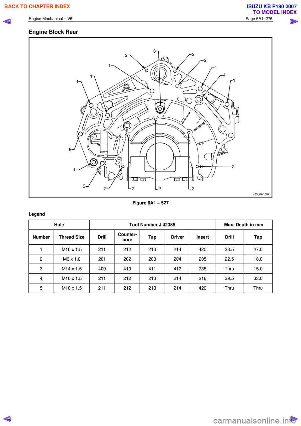
Engine Block Rear
Figure 6A1 – 527
Legend Hole Tool Number J 42385 Max. Depth in mm
Number Thread Size Drill Counter-
bore Tap Driver Insert Drill Tap
1 M10 x 1.5 211 212 213 214 420 33.5 27.0
2 M6 x 1.0 201 202 203 204 205 22.5 18.0
3 M14 x 1.5 409 410 411 412 735 Thru 15.0
4 M10 x 1.5 211 212 213 214 216 39.5 33.0
5 M10 x 1.5 211 212 213 214 420 Thru Thru
BACK TO CHAPTER INDEX
TO MODEL INDEX
ISUZU KB P190 2007
Page 2756 of 6020
Engine Mechanical – V6 Page 6A1–277
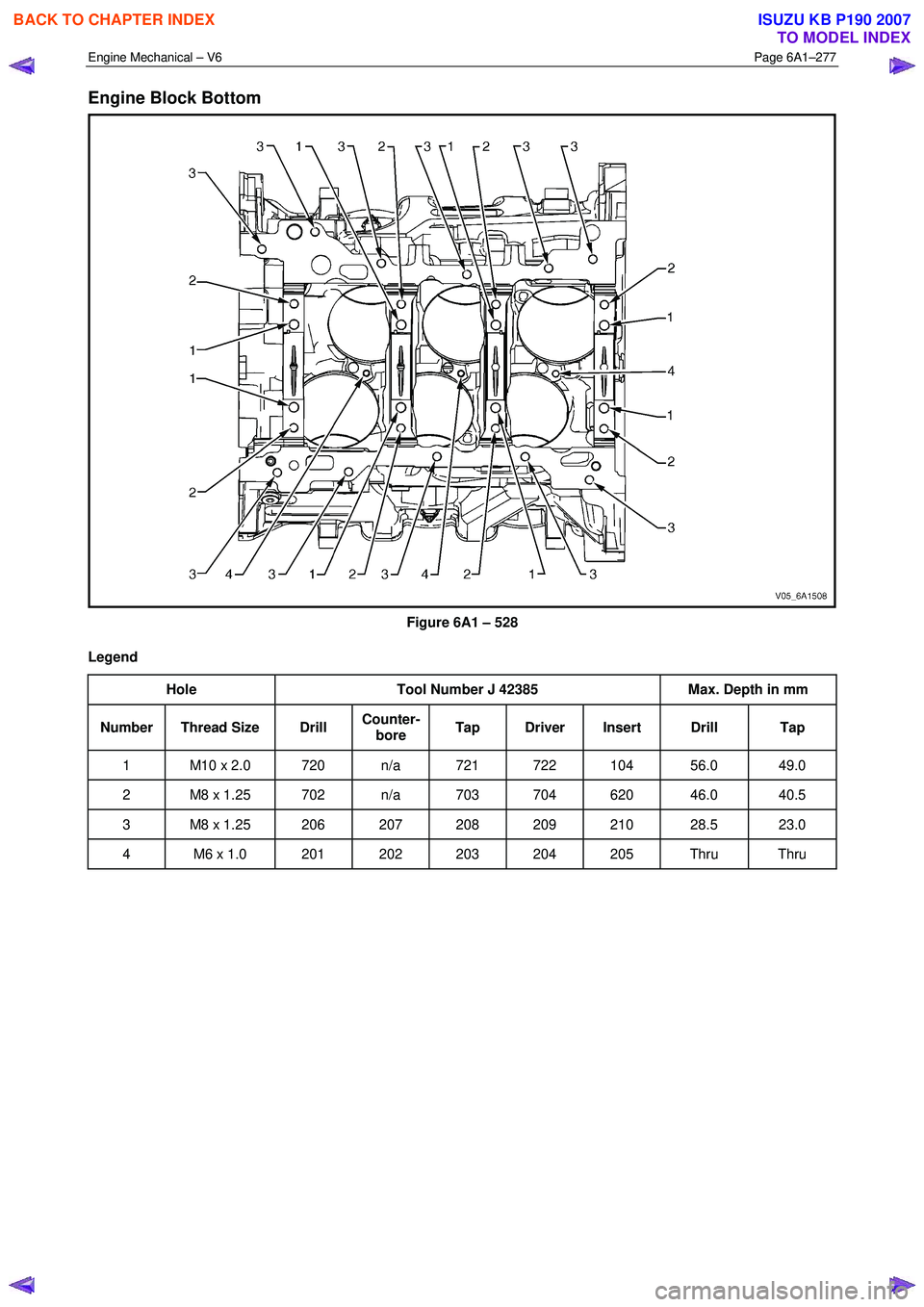
Engine Block Bottom
Figure 6A1 – 528
Legend Hole Tool Number J 42385 Max. Depth in mm
Number Thread Size Drill Counter-
bore Tap Driver Insert Drill Tap
1 M10 x 2.0 720 n/a 721 722 104 56.0 49.0
2 M8 x 1.25 702 n/a 703 704 620 46.0 40.5
3 M8 x 1.25 206 207 208 209 210 28.5 23.0
4 M6 x 1.0 201 202 203 204 205 Thru Thru
BACK TO CHAPTER INDEX
TO MODEL INDEX
ISUZU KB P190 2007
Page 2757 of 6020
Engine Mechanical – V6 Page 6A1–278
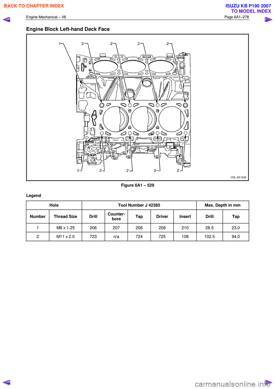
Engine Block Left-hand Deck Face
Figure 6A1 – 529
Legend Hole Tool Number J 42385 Max. Depth in mm
Number Thread Size Drill Counter-
bore Tap Driver Insert Drill Tap
1 M8 x 1.25 206 207 208 209 210 28.5 23.0
2 M11 x 2.0 723 n/a 724 725 108 102.5 94.0
BACK TO CHAPTER INDEX
TO MODEL INDEX
ISUZU KB P190 2007
Page 2758 of 6020
Engine Mechanical – V6 Page 6A1–279
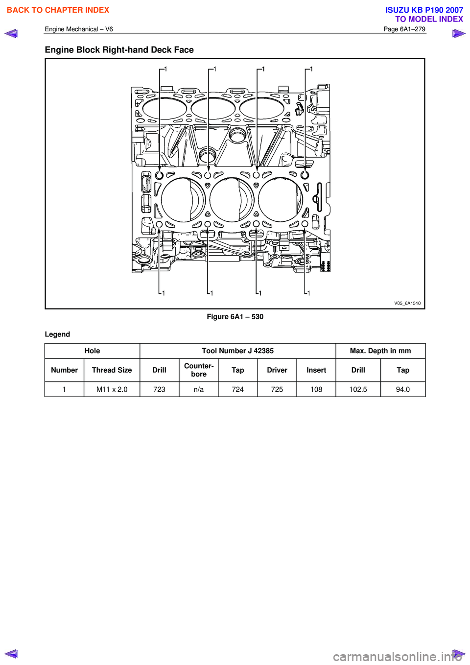
Engine Block Right-hand Deck Face
Figure 6A1 – 530
Legend Hole Tool Number J 42385 Max. Depth in mm
Number Thread Size Drill Counter-
bore Tap Driver Insert Drill Tap
1 M11 x 2.0 723 n/a 724 725 108 102.5 94.0
BACK TO CHAPTER INDEX
TO MODEL INDEX
ISUZU KB P190 2007
Page 2767 of 6020

Engine Mechanical – V6 Page 6A1–288
5 Specifications
General
Engine Type.................................................................................................................... ..... V6
Bank Angle ..................................................................................................................... .... 60°
Displacement ............................................................................................ 3.6 litre (3,565 cm3)
Bore ........................................................................................................................... .... 94 mm
Stroke ......................................................................................................................... 85.6 mm
Compression Ratio ......................................................................................................... 10.2: 1
Cranking Speed at 40 °C .............................................................................................80 r.p.m.
Spark Plug Gap ............................................................................................................ 1.1 m m
Firing Order............................................................................................................. 1-2-3- 4-5-6
Cylinder Block
Cylinder Bore Diameter ........................................................................... 93.992 – 94.008 mm
Cylinder Out-of-Round – Production Maximum ........................................................ 0.013 mm
Crankshaft Main bearing bore Diameter .................................................. 72.867 – 72.881 mm
Cylinder Head Deck Surface Flatness ........................................................................ 0.05 mm
Crankshaft
Connecting Rod Journal Diameter ........................................................... 55.992 – 56.008 mm
Connecting Rod Journal Out-of-Round..................................................................... 0.005 mm
Connecting Rod Journal Taper ................................................................................ .0.005 mm
Connecting Rod Journal Width (Production)........................................................... 22.000 mm
Connecting Rod Journal Width (Service limit).......................................... 21.920 – 22.080 mm
Crankshaft End Play .................................................................................... 0.100 – 0.330 mm
Crankshaft Main Bearing Clearance ............................................................ 0.010 – 0.060 mm
Crankshaft Main Journal Diameter ......................................................... .67.992 – 68.008 mm
Crankshaft Main Journal Out-of-Round .................................................................... 0.005 mm
Crankshaft Main Journal Taper................................................................................ .0.005 mm
Crankshaft Main Journal Width, #2, 4 (Production) ....................................................... 24 mm
Crankshaft Main Journal Width, #2, 4 (Service)....................................... 23.900 – 24.100 mm
Crankshaft Main Journal Width, #3 (Production) .................................................... 24.400 mm
Crankshaft Main Journal Width, #3 (Service) .......................................... 24.360 – 24.440 mm
Crankshaft Main Journal Thrust Wall Runout .............................................. 0.000 – 0.040 mm
Crankshaft Main Journal Thrust Wall Square .............................................. 0.000 – 0.010 mm
Crankshaft Rear Flange Runout ............................................................................... 0.025 mm
Crankshaft Reluctor Ring Runout - Maximum........................................................... 1.500 mm
Crankshaft Thrust Bearing Clearance.......................................................... 0.076 – 0.305 mm
Crankshaft Thrust Surface Runout ........................................................................... 0.040 mm
Crankshaft Thrust Surface – Height Diameter ........................................................ 95.000 mm
Connecting Rod
Connecting Rod Length - Bore Centre-to-Centre.................................................. 150.400 mm
Connecting Rod Bore Diameter - Bearing End ........................................ 59.620 – 59.636 mm
Connecting Rod Bore Diameter - Pin End ............................................... 24.007 – 24.021 mm
Connecting Rod Width ........................................................................................... 21.775 mm
Connecting Rod Side Clearance.................................................................. 0.095 – 0.355 mm
Connecting Rod Bearing Clearance ............................................................ 0.010 – 0.070 mm
Piston
Piston Diameter ....................................................................................... 93.956 – 93.974 mm
Piston Pin Bore Diameter ........................................................................ 24.005 – 24.009 mm
Piston Ring Groove Width - First (Top) Compression Ring ......................... 1.220 – 1.240 mm
Piston Ring Groove Width - Second Compression Ring .............................. 1.510 – 1.530 mm
BACK TO CHAPTER INDEX
TO MODEL INDEX
ISUZU KB P190 2007
Page 2768 of 6020

Engine Mechanical – V6 Page 6A1–289
Piston Ring Groove Width - Oil Control Ring ............................................... 2.510 – 2.530 mm
Piston to Bore Clearance ............................................................................. 0.026 – 0.052 mm
Piston Pin
Piston Pin Diameter ..................................................................................23.997 - 24.000 mm
Piston Pin Length..................................................................................... 60.600 – 61.100 mm
Piston Pin Clearance to Connecting Rod Bore ............................................. 0.007 – 0.024mm
Piston Pin Clearance to Piston Pin Bore....................................................... 0.004 – 0.012mm
Piston Rings
Piston Ring to Groove Clearance:
• First (Top) Compression Ring............................................................... 0.030 – 0.065 mm
• Second Compression Ring ................................................................... 0.015 – 0.060 mm
• Oil Control Ring .................................................................................... 0.030 – 0.170 mm
Piston Ring End Gap:
• First (Top) Compression Ring............................................................... 0.150 – 0.300 mm
• Second Compression Ring ................................................................... 0.280 – 0.480 mm
• Oil Control Ring .................................................................................... 0.150 – 0.600 mm
Cylinder Head
Combustion Chamber Volume.................................................................................. 53.600 cc
Valve Guide Bore Diameter – Intake ........................................................... 6.000 – 6.020 mm
Valve Guide Bore Diameter – Exhaust ........................................................ 6.000 – 6.020 mm
Valve Guide Installed Height.................................................................... 14.050 – 14.550 mm
Stationary Hydraulic Lash Adjuster (SHLA) Bore Diameter ..................... 12.008 – 12.030 mm
Valve Seat Angle – Seating Surface ................................................................................... 45 °
Valve Seat Angle – Relief Surface ...................................................................................... 30 °
Valve Seat Angle – Undercut Surface ................................................................................ 60 °
Valve Seat Runout – Maximum ................................................................................ 0.050 mm
Valve Seat Width – Exhaust Seating Surface .............................................. 1.400 – 1.800 mm
Valve Seat Width – Exhaust Relief Surface ................................................. 0.700 – 0.900 mm
Valve Seat Width – Intake Seating Surface ................................................. 1.000 – 1.400 mm
Valve Seat Width – Intake Relief Surface .................................................... 0.500 – 0.700 mm
Engine Block Deck Surface Flatness .......................................................................... 0.05 mm
Exhaust Manifold Deck Surface Flatness ................................................................... 0.25 mm
Intake Manifold Deck Surface Flatness ...................................................................... 0.05 mm
Valve System
Face Angle..................................................................................................................... 44.25°
Face Runout ............................................................................................................. 0.038 m m
Valve Face Width – Exhaust..................................................................................... 2.750 mm
Valve Face Width – Intake ........................................................................................ 2.180 mm
Valve Head Diameter – Exhaust .............................................................. 30.470 – 30.730 mm
Valve Head Diameter – Intake ................................................................. 36.830 – 37.090 mm
Valve Installed Height .................................................................................. 35.26 – 36.69 mm
Valve Length – Exhaust .......................................................................................... 97.110 mm
Valve Length – Intake ........................................................................................... 101.230 mm
Valve Stem Diameter (standard).................................................................. 5.955 – 5.975 mm
Valve Stem Diameter (oversize) .................................................................. 6.013 – 6.033 mm
Valve Stem to Guide Clearance................................................................... 0.025 – 0.065 mm
Hydraulic Lash Adjuster Diameter ........................................................... 11.986 – 12.000 mm
Hydraulic Lash Adjuster to Bore Clearance ................................................. 0.037 – 0.041 mm
Rocker Arm/Camshaft Follower Ratio............................................................................. 1.68:1
Rocker Arm/Camshaft Follower Roller Diameter ..................................... 17.740 – 17.800 mm
Valve Spring Free Length ........................................................................ 42.500 – 45.500 mm
BACK TO CHAPTER INDEX
TO MODEL INDEX
ISUZU KB P190 2007