lock ISUZU KB P190 2007 Workshop Repair Manual
[x] Cancel search | Manufacturer: ISUZU, Model Year: 2007, Model line: KB P190, Model: ISUZU KB P190 2007Pages: 6020, PDF Size: 70.23 MB
Page 2703 of 6020
Engine Mechanical – V6 Page 6A1–224
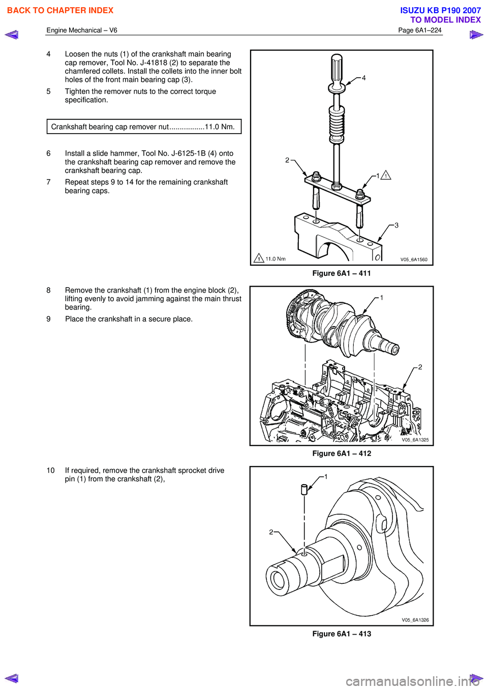
4 Loosen the nuts (1) of the crankshaft main bearing
cap remover, Tool No. J-41818 (2) to separate the
chamfered collets. Install the collets into the inner bolt
holes of the front main bearing cap (3).
5 Tighten the remover nuts to the correct torque specification.
Crankshaft bearing cap remover nut .................11.0 Nm.
6 Install a slide hammer, Tool No. J-6125-1B (4) onto the crankshaft bearing cap remover and remove the
crankshaft bearing cap.
7 Repeat steps 9 to 14 for the remaining crankshaft bearing caps.
Figure 6A1 – 411
8 Remove the crankshaft (1) from the engine block (2), lifting evenly to avoid jamming against the main thrust
bearing.
9 Place the crankshaft in a secure place.
Figure 6A1 – 412
10 If required, remove the crankshaft sprocket drive pin (1) from the crankshaft (2),
Figure 6A1 – 413
BACK TO CHAPTER INDEX
TO MODEL INDEX
ISUZU KB P190 2007
Page 2704 of 6020
Engine Mechanical – V6 Page 6A1–225
Crankshaft Bearing
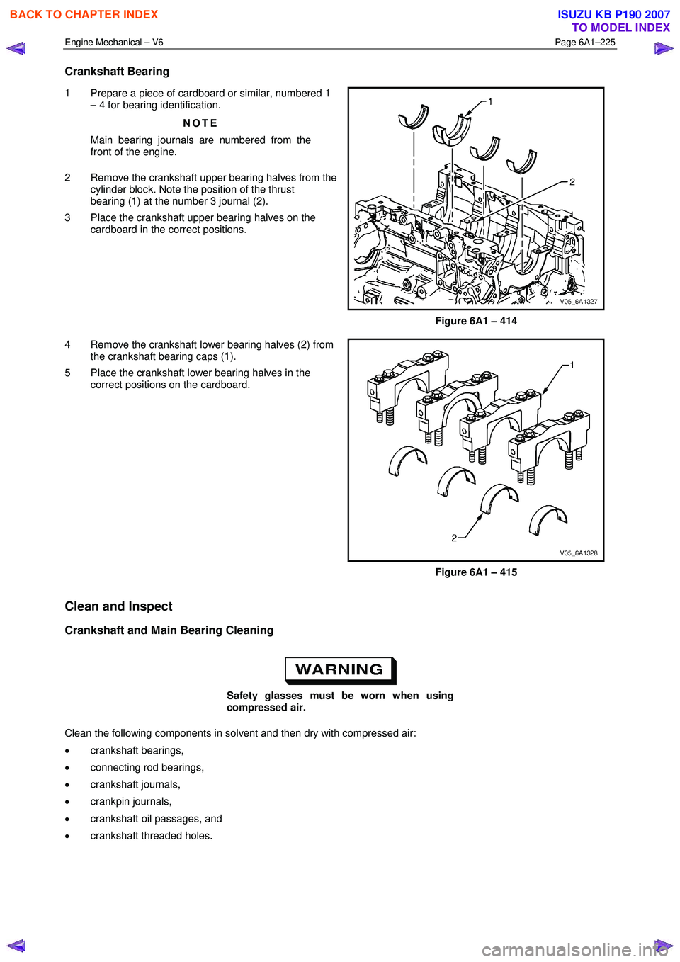
1 Prepare a piece of cardboard or similar, numbered 1
– 4 for bearing identification.
NOTE
Main bearing journals are numbered from the
front of the engine.
2 Remove the crankshaft upper bearing halves from the cylinder block. Note the position of the thrust
bearing (1) at the number 3 journal (2).
3 Place the crankshaft upper bearing halves on the cardboard in the correct positions.
Figure 6A1 – 414
4 Remove the crankshaft lower bearing halves (2) from the crankshaft bearing caps (1).
5 Place the crankshaft lower bearing halves in the correct positions on the cardboard.
Figure 6A1 – 415
Clean and Inspect
Crankshaft and Main Bearing Cleaning
Safety glasses must be worn when using
compressed air.
Clean the following components in solvent and then dry with compressed air:
• crankshaft bearings,
• connecting rod bearings,
• crankshaft journals,
• crankpin journals,
• crankshaft oil passages, and
• crankshaft threaded holes.
BACK TO CHAPTER INDEX
TO MODEL INDEX
ISUZU KB P190 2007
Page 2709 of 6020
Engine Mechanical – V6 Page 6A1–230
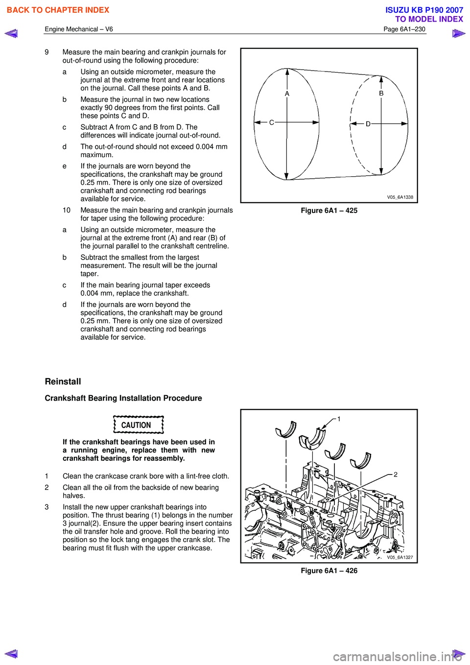
9 Measure the main bearing and crankpin journals for
out-of-round using the following procedure:
a Using an outside micrometer, measure the journal at the extreme front and rear locations
on the journal. Call these points A and B.
b Measure the journal in two new locations exactly 90 degrees from the first points. Call
these points C and D.
c Subtract A from C and B from D. The differences will indicate journal out-of-round.
d The out-of-round should not exceed 0.004 mm maximum.
e If the journals are worn beyond the specifications, the crankshaft may be ground
0.25 mm. There is only one size of oversized
crankshaft and connecting rod bearings
available for service.
10 Measure the main bearing and crankpin journals for taper using the following procedure:
a Using an outside micrometer, measure the journal at the extreme front (A) and rear (B) of
the journal parallel to the crankshaft centreline.
b Subtract the smallest from the largest measurement. The result will be the journal
taper.
c If the main bearing journal taper exceeds 0.004 mm, replace the crankshaft.
d If the journals are worn beyond the specifications, the crankshaft may be ground
0.25 mm. There is only one size of oversized
crankshaft and connecting rod bearings
available for service.
Figure 6A1 – 425
Reinstall
Crankshaft Bearing Installation Procedure
CAUTION
If the crankshaft bearings have been used in
a running engine, replace them with new
crankshaft bearings for reassembly.
1 Clean the crankcase crank bore with a lint-free cloth.
2 Clean all the oil from the backside of new bearing halves.
3 Install the new upper crankshaft bearings into position. The thrust bearing (1) belongs in the number
3 journal(2). Ensure the upper bearing insert contains
the oil transfer hole and groove. Roll the bearing into
position so the lock tang engages the crank slot. The
bearing must fit flush with the upper crankcase.
Figure 6A1 – 426
BACK TO CHAPTER INDEX
TO MODEL INDEX
ISUZU KB P190 2007
Page 2711 of 6020
Engine Mechanical – V6 Page 6A1–232
NOTE
Do not rotate the crankshaft.
9 Allow the assembly to sit for 2 minutes.
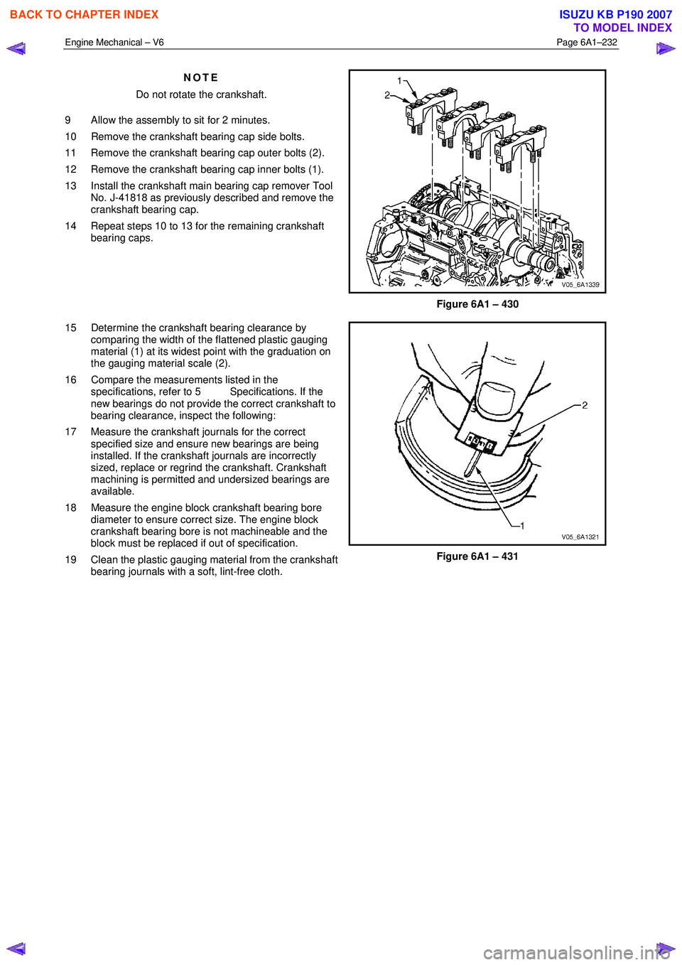
10 Remove the crankshaft bearing cap side bolts.
11 Remove the crankshaft bearing cap outer bolts (2).
12 Remove the crankshaft bearing cap inner bolts (1).
13 Install the crankshaft main bearing cap remover Tool No. J-41818 as previously described and remove the
crankshaft bearing cap.
14 Repeat steps 10 to 13 for the remaining crankshaft bearing caps.
Figure 6A1 – 430
15 Determine the crankshaft bearing clearance by comparing the width of the flattened plastic gauging
material (1) at its widest point with the graduation on
the gauging material scale (2).
16 Compare the measurements listed in the specifications, refer to 5 Specifications. If the
new bearings do not provide the correct crankshaft to
bearing clearance, inspect the following:
17 Measure the crankshaft journals for the correct specified size and ensure new bearings are being
installed. If the crankshaft journals are incorrectly
sized, replace or regrind the crankshaft. Crankshaft
machining is permitted and undersized bearings are
available.
18 Measure the engine block crankshaft bearing bore diameter to ensure correct size. The engine block
crankshaft bearing bore is not machineable and the
block must be replaced if out of specification.
19 Clean the plastic gauging material from the crankshaft bearing journals with a soft, lint-free cloth.
Figure 6A1 – 431
BACK TO CHAPTER INDEX
TO MODEL INDEX
ISUZU KB P190 2007
Page 2712 of 6020

Engine Mechanical – V6 Page 6A1–233
Crankshaft Final Installation Procedure
1 If removed, install the crankshaft sprocket drive
pin (1). Lightly tap the pin in place with a small soft
face, bronze/plastic, hammer until it bottoms in the
hole.
Figure 6A1 – 432
CAUTION
Ensure the crankshaft position sensor has
been removed from the cylinder block prior
to loading the crankshaft, as damage to the
sensor may occur.
2
Apply a liberal amount of clean engine oil to the upper
and lower bearing surfaces.
3 Gently lower the crankshaft (1) into position in the cylinder block (2).
Figure 6A1 – 433
4 Install the crankshaft main bearing caps.
5 Loosely install the original inner main cap bolts (1).
CAUTION
The outer crankshaft bearing cap bolts (2)
are yield tightened during assembly and
must be replaced prior to reassembly. Outer
crankshaft bearing cap bolts that are not
replaced will not torque to the correct clamp
load and can lead to serious engine damage.
6 Loosely install the new outer main bearing cap bolts (2).
7 Gently tap the crankshaft main bearing caps with a soft-faced hammer to help seat the caps.
Figure 6A1 – 434
BACK TO CHAPTER INDEX
TO MODEL INDEX
ISUZU KB P190 2007
Page 2713 of 6020
Engine Mechanical – V6 Page 6A1–234
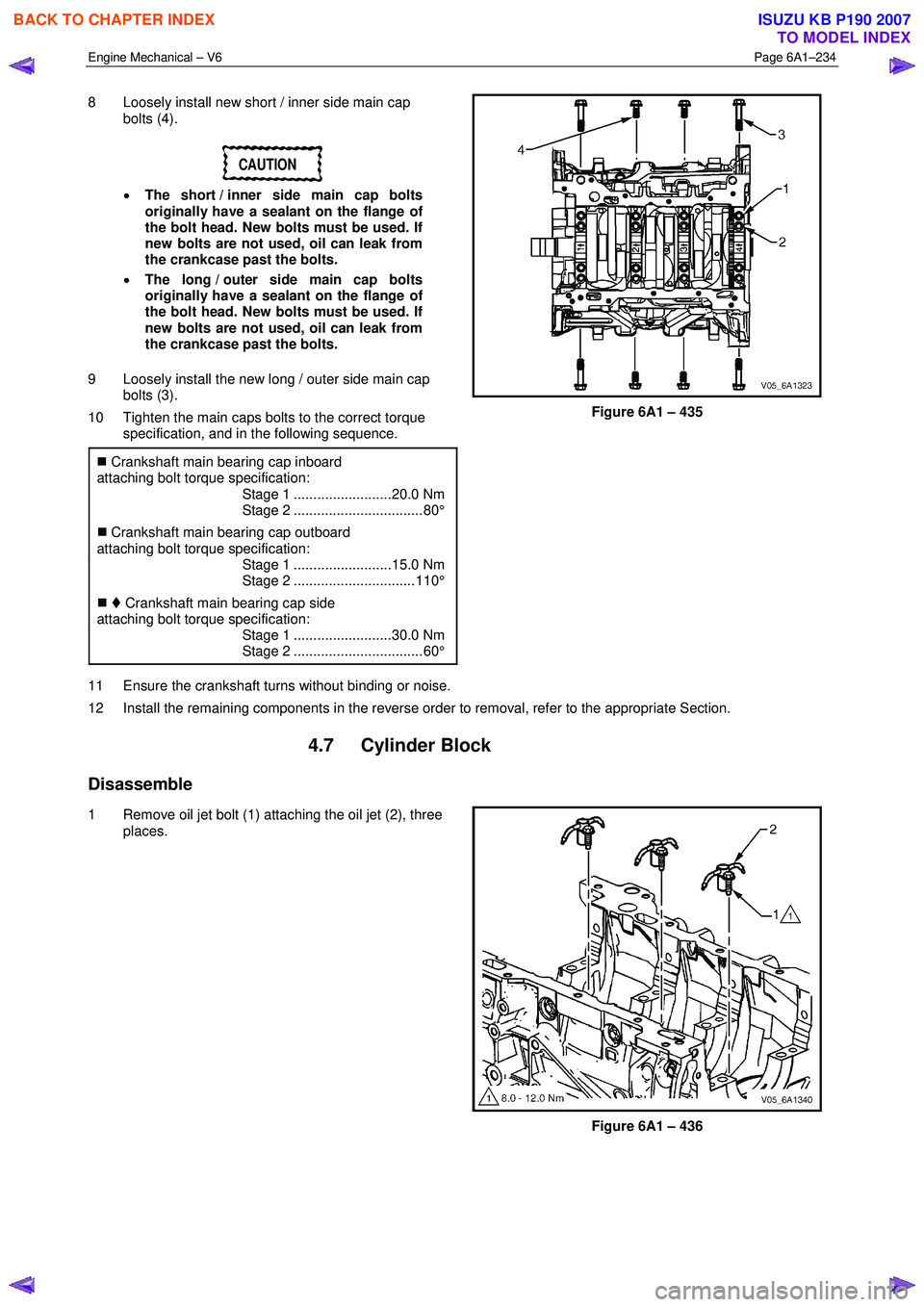
8 Loosely install new short / inner side main cap
bolts (4).
CAUTION
• The short / inner side main cap bolts
originally have a sealant on the flange of
the bolt head. New bolts must be used. If
new bolts are not used, oil can leak from
the crankcase past the bolts.
• The long / outer side main cap bolts
originally have a sealant on the flange of
the bolt head. New bolts must be used. If
new bolts are not used, oil can leak from
the crankcase past the bolts.
9 Loosely install the new long / outer side main cap bolts (3).
10 Tighten the main caps bolts to the correct torque specification, and in the following sequence.
�„ Crankshaft main bearing cap inboard
attaching bolt torque specification:
Stage 1 .........................20.0 Nm
Stage 2 ................................. 80°
�„ Crankshaft main bearing cap outboard
attaching bolt torque specification:
Stage 1 .........................15.0 Nm
Stage 2 ............................... 110°
�„ Crankshaft main bearing cap side
attaching bolt torque specification:
Stage 1 .........................30.0 Nm
Stage 2 ................................. 60°
Figure 6A1 – 435
11 Ensure the crankshaft turns without binding or noise.
12 Install the remaining components in the reverse order to removal, refer to the appropriate Section.
4.7 Cylinder Block
Disassemble
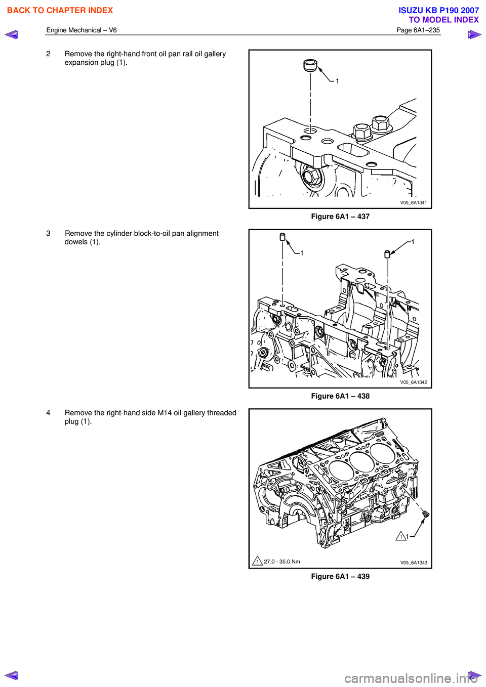
1 Remove oil jet bolt (1) attaching the oil jet (2), three places.
Figure 6A1 – 436
BACK TO CHAPTER INDEX
TO MODEL INDEX
ISUZU KB P190 2007
Page 2714 of 6020
Engine Mechanical – V6 Page 6A1–235
2 Remove the right-hand front oil pan rail oil gallery
expansion plug (1).
Figure 6A1 – 437
3 Remove the cylinder block-to-oil pan alignment dowels (1).
Figure 6A1 – 438
4 Remove the right-hand side M14 oil gallery threaded plug (1).
Figure 6A1 – 439
BACK TO CHAPTER INDEX
TO MODEL INDEX
ISUZU KB P190 2007
Page 2716 of 6020

Engine Mechanical – V6 Page 6A1–237
8 Remove the left-hand side M20 oil gallery threaded
plug (1).
Figure 6A1 – 443
CAUTION
Do not force coolant expansion plugs
downwards during removal procedure as the
cylinder block will be damaged.
9 Remove the coolant expansion plugs (1).
Figure 6A1 – 444
10 Remove the cylinder block-to-transmission alignment dowels (1).
Figure 6A1 – 445
BACK TO CHAPTER INDEX
TO MODEL INDEX
ISUZU KB P190 2007
Page 2717 of 6020
Engine Mechanical – V6 Page 6A1–238
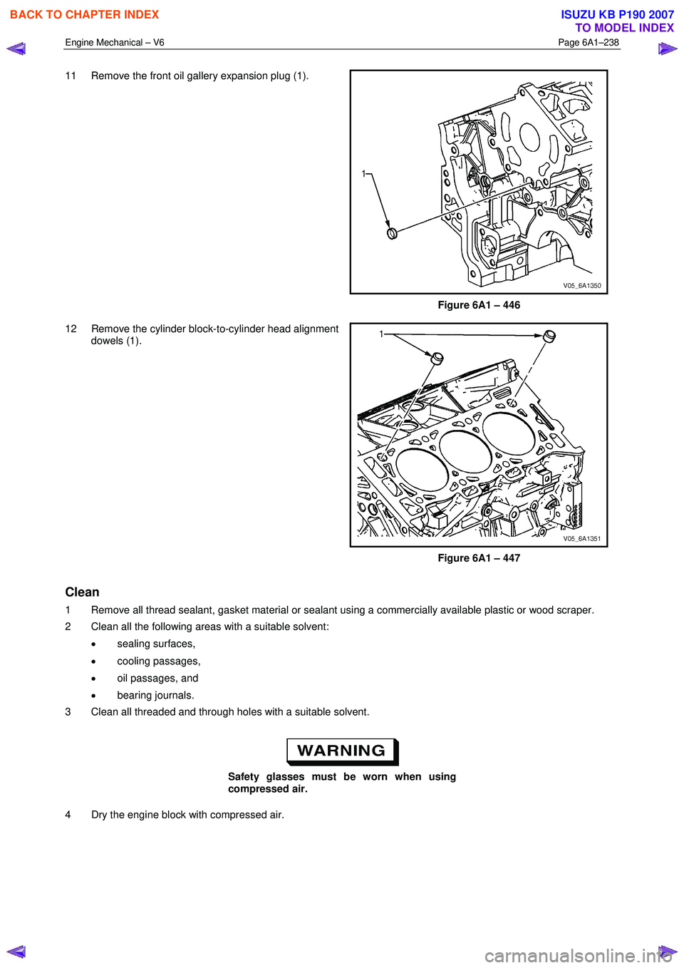
11 Remove the front oil gallery expansion plug (1).
Figure 6A1 – 446
12 Remove the cylinder block-to-cylinder head alignment dowels (1).
Figure 6A1 – 447
Clean
1 Remove all thread sealant, gasket material or sealant using a commercially available plastic or wood scraper.
2 Clean all the following areas with a suitable solvent:
• sealing surfaces,
• cooling passages,
• oil passages, and
• bearing journals.
3 Clean all threaded and through holes with a suitable solvent.
Safety glasses must be worn when using
compressed air.
4 Dry the engine block with compressed air.
BACK TO CHAPTER INDEX
TO MODEL INDEX
ISUZU KB P190 2007
Page 2718 of 6020
Engine Mechanical – V6 Page 6A1–239
Inspect
Visual Inspection
NOTE
The following procedure assumes the engine has
been disassembled and cleaned, as described
above.
1 Inspect the crankshaft bearing journals for damage or spun bearings. The crankshaft bearing journals are not repairable and if damage is found, the cylinder block assembly must be replaced.
2 Inspect the primary camshaft chain tensioner mounting surface on the engine block for burrs or any defects that would affect the sealing of the new primary camshaft chain tensioner gasket.
3 Inspect all sealing and mating surfaces for damage, repair or replace the cylinder block assembly if required.
4 Inspect all threaded and through holes for damage or excessive debris.
5 Inspect all bolts for damage, if damaged replace with new bolts only.
6 Inspect the cylinder walls for cracks or damage. The cylinder sleeves are not serviced separately, if the cylinders are damaged the cylinder block assembly must be replaced.
7 Inspect the engine block for cracks. Do not repair any cracks. If cracks are found, the cylinder block assembly must be replaced. Repair any damaged threaded holes, refer to 4.9 Thread Repair Specifications.
Measuring Cylinder Bore Diameter
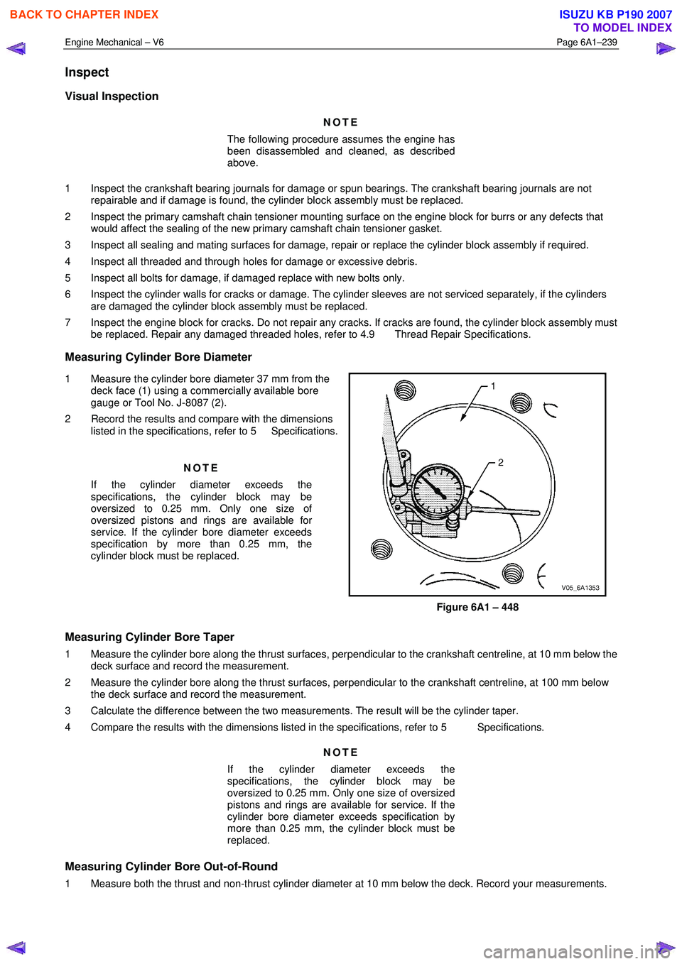
1 Measure the cylinder bore diameter 37 mm from the deck face (1) using a commercially available bore
gauge or Tool No. J-8087 (2).
2 Record the results and compare with the dimensions listed in the specifications, refer to 5 Specifications.
NOTE
If the cylinder diameter exceeds the
specifications, the cylinder block may be
oversized to 0.25 mm. Only one size of
oversized pistons and rings are available for
service. If the cylinder bore diameter exceeds
specification by more than 0.25 mm, the
cylinder block must be replaced.
Figure 6A1 – 448
Measuring Cylinder Bore Taper
1 Measure the cylinder bore along the thrust surfaces, perpendicular to the crankshaft centreline, at 10 mm below the deck surface and record the measurement.
2 Measure the cylinder bore along the thrust surfaces, perpendicular to the crankshaft centreline, at 100 mm below the deck surface and record the measurement.
3 Calculate the difference between the two measurements. The result will be the cylinder taper.
4 Compare the results with the dimensions listed in the specifications, refer to 5 Specifications.
NOTE
If the cylinder diameter exceeds the
specifications, the cylinder block may be
oversized to 0.25 mm. Only one size of oversized
pistons and rings are available for service. If the
cylinder bore diameter exceeds specification by
more than 0.25 mm, the cylinder block must be
replaced.
Measuring Cylinder Bore Out-of-Round
1 Measure both the thrust and non-thrust cylinder diameter at 10 mm below the deck. Record your measurements.
BACK TO CHAPTER INDEX
TO MODEL INDEX
ISUZU KB P190 2007