ISUZU KB P190 2007 Workshop Repair Manual
Manufacturer: ISUZU, Model Year: 2007, Model line: KB P190, Model: ISUZU KB P190 2007Pages: 6020, PDF Size: 70.23 MB
Page 4461 of 6020
ON-VEHICLE SERVICE (JR405E) 7A3-7
Install or Connect
1. Install the inhibitor switch to the transmission.
Temporarily tighten the inhibitor switch bolts.
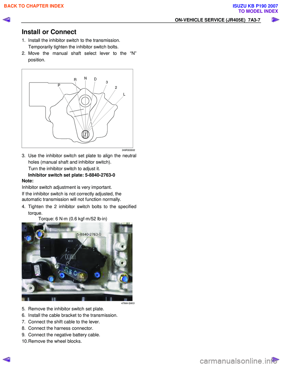
2. Move the manual shaft select lever to the “N” position.
249R300002
3. Use the inhibitor switch set plate to align the neutral
holes (manual shaft and inhibitor switch).
Turn the inhibitor switch to adjust it.
Inhibitor switch set plate: 5-8840-2763-0
Note:
Inhibitor switch adjustment is very important.
If the inhibitor switch is not correctly adjusted, the
automatic transmission will not function normally.
4. Tighten the 2 inhibitor switch bolts to the specified torque.
Torque: 6 N·m (0.6 kgf·m/52 lb·in)
47INH-SW 01
5. Remove the inhibitor switch set plate.
6. Install the cable bracket to the transmission.
7. Connect the shift cable to the lever.
8. Connect the harness connector.
9. Connect the negative battery cable.
10. Remove the wheel blocks.
BACK TO CHAPTER INDEX
TO MODEL INDEX
ISUZU KB P190 2007
Page 4462 of 6020

7A3-8 ON-VEHICLE SERVICE (JR405E)
SPEED SENSOR
The speed sensor is attached to the right side of the
transmission.
240L300001
Legend
1. Inhibitor switch
2. Speed sensor
3. Turbine sensor
Inspect
1. During driving at a speed of 20km/h (12mph) with “L”
range in low gear, measure the voltage between the
TCM connector terminals (B13) and (B5) with a
digital voltmeter.
Standard voltage : approx. 7V (AC range)
RTW 47ASH000801
2. If the voltage is outside of the standard value, check
the speed sensor pole piece for the presence o
f
foreign materials and the speeed sensor cable for a
short or open circuit.
If the result of the inspection is normal, replace the speed sensor.
Torque: 6 N·m (0.6 kgf·m/52 lb·in)
BACK TO CHAPTER INDEX
TO MODEL INDEX
ISUZU KB P190 2007
Page 4463 of 6020

ON-VEHICLE SERVICE (JR405E) 7A3-9
TURBINE SENSOR
The turbine sensor is attached to the right side of the
transmission.
Inspect
1. During driving at a speed of 20km/h (12mph) with “L” range in low gear, measure the voltage between the
TCM connector terminals (B3) and (B5) with a digital
voltmeter.
Standard voltage : approx. 7V (AC range)
2. If the voltage is outside of the standard value, check the turbine sensor pole piece for presence of foreign
materials and the turbine sensor cable for a short o
r
open circuit.
If the result of the inspection is abnormal, replace the turbine sensor.
Torque: 6 N·m (0.6 kgf·m/52 lb·in)
POWER AND 3RD START SWITCH
Inspect
1. Block the wheels.
2. Disconnect the negative battery cable.
3. Pry out the switch from the floor console.
4. Disconnect the harness connector.
5. Check continuity between terminals (5) and (6) at third (3rd) position.
6. Check continuity between terminals (3) and (6) at power (PW R) position.
7. Replace the power and 3rd start switch if the result o
f
inspection is abnormal.
8. Connect the harness connector.
9. Connect the negative battery cable.
10. Remove the wheel blocks.
238R300003
BACK TO CHAPTER INDEX
TO MODEL INDEX
ISUZU KB P190 2007
Page 4464 of 6020
7A3-10 ON-VEHICLE SERVICE (JR405E)
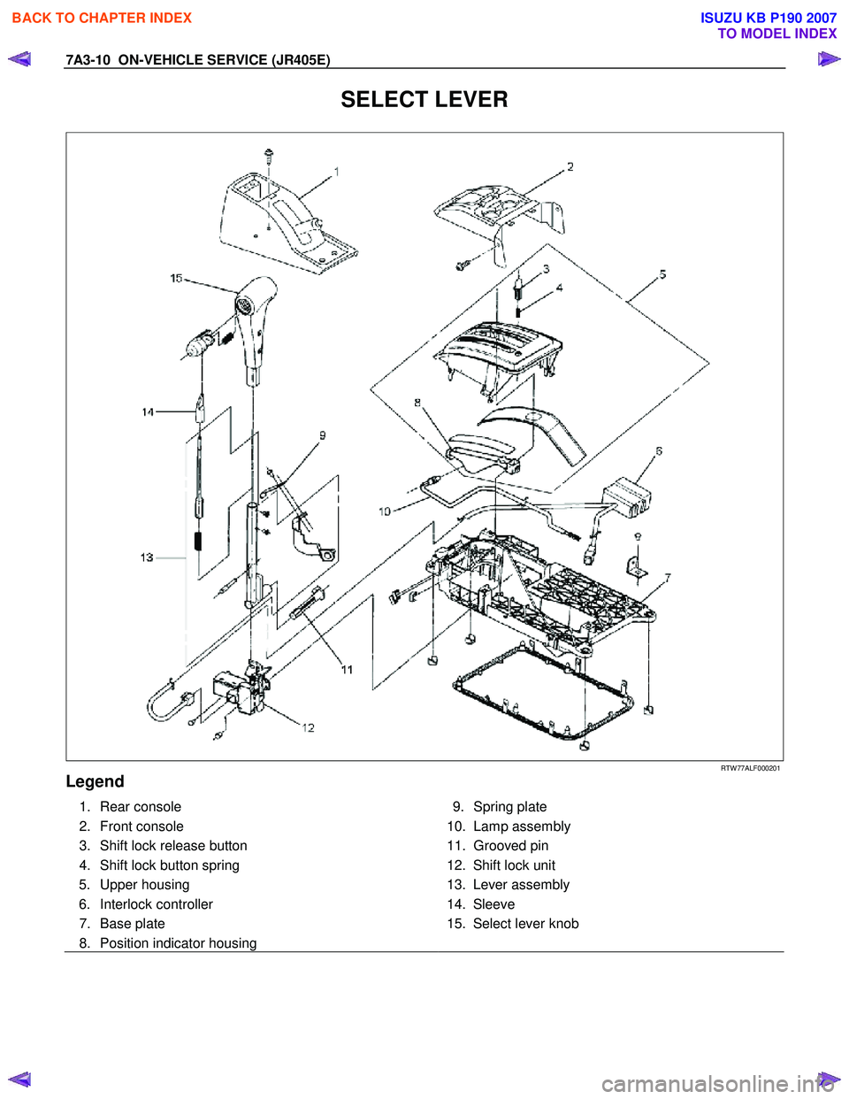
SELECT LEVER
RTW 77ALF000201
Legend
1. Rear console
2. Front console
3. Shift lock release button
4. Shift lock button spring 5. Upper housing
6. Interlock controller
7. Base plate
8. Position indicator housing
9. Spring plate
10. Lamp assembly
11. Grooved pin
12. Shift lock unit
13. Lever assembly
14. Sleeve
15. Select lever knob
BACK TO CHAPTER INDEX
TO MODEL INDEX
ISUZU KB P190 2007
Page 4465 of 6020
ON-VEHICLE SERVICE (JR405E) 7A3-11
Remove or Disconnect
1. Block the wheels.
2. Disconnect the negative battery cable.
3. Remove the rear console and the front console.
4. Remove the 2 screws fixing the select lever knob.
5. Remove the knob together with the knob button and spring from the lever.
6. Turn the sleeve counterclockwise to remove it. Make a note of the number of turns required to free
the sleeve.
7. Remove the harness connectors from the base plate.
8. Remove the upper housing (held in place by 4 latched fasteners).
9. Remove the lamp assembly by turning it counterclockwise.
10. Remove the spring plate.
11. Remove the grooved pin.
12. Disconnect the shift cable from the select lever.
13. Remove the lever assembly by pressing the rod down (lever in N position).
14. Remove the harness connectors from the shift lock unit, then remove the shift lock unit.
15. Remove the interlock controller.
16. If the replacement of shift lock release button o
r
shift lock button spring is required, remove the
position indicator housing, the shift lock button
spring and shift lock release button can be
removed.
Install or Connect
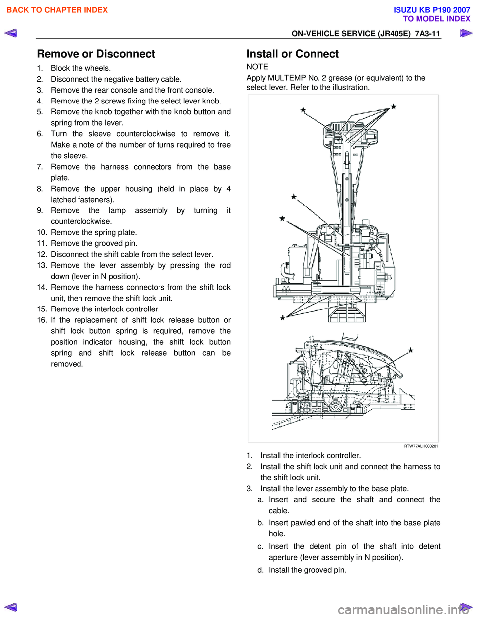
NOTE
Apply MULTEMP No. 2 grease (or equivalent) to the
select lever. Refer to the illustration.
RTW 77ALH000201
1. Install the interlock controller.
2. Install the shift lock unit and connect the harness to the shift lock unit.
3. Install the lever assembly to the base plate. a. Insert and secure the shaft and connect the cable.
b. Insert pawled end of the shaft into the base plate hole.
c. Insert the detent pin of the shaft into detent aperture (lever assembly in N position).
d. Install the grooved pin.
BACK TO CHAPTER INDEX
TO MODEL INDEX
ISUZU KB P190 2007
Page 4466 of 6020
7A3-12 ON-VEHICLE SERVICE (JR405E)
4. Install the spring plate.
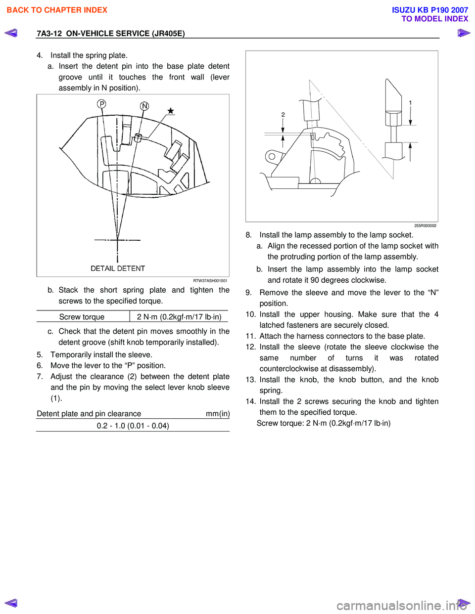
a. Insert the detent pin into the base plate detent groove until it touches the front wall (leve
r
assembly in N position).
RTW 37ASH001001
b. Stack the short spring plate and tighten thescrews to the specified torque.
Screw torque 2 N ⋅m (0.2kgf ⋅m/17 lb ⋅in)
c. Check that the detent pin moves smoothly in the
detent groove (shift knob temporarily installed).
5. Temporarily install the sleeve.
6. Move the lever to the “P” position.
7. Adjust the clearance (2) between the detent plate and the pin by moving the select lever knob sleeve
(1).
Detent plate and pin clearance mm(in
)
0.2 - 1.0 (0.01 - 0.04)
255R300002
8. Install the lamp assembly to the lamp socket.
a.
Align the recessed portion of the lamp socket with
the protruding portion of the lamp assembly.
b. Insert the lamp assembly into the lamp socket and rotate it 90 degrees clockwise.
9. Remove the sleeve and move the lever to the “N” position.
10. Install the upper housing. Make sure that the 4 latched fasteners are securely closed.
11. Attach the harness connectors to the base plate.
12. Install the sleeve (rotate the sleeve clockwise the same number of turns it was rotated
counterclockwise at disassembly).
13. Install the knob, the knob button, and the knob spring.
14. Install the 2 screws securing the knob and tighten them to the specified torque.
Screw torque: 2 N ⋅m (0.2kgf ⋅m/17 lb ⋅in)
BACK TO CHAPTER INDEX
TO MODEL INDEX
ISUZU KB P190 2007
Page 4467 of 6020
ON-VEHICLE SERVICE (JR405E) 7A3-13
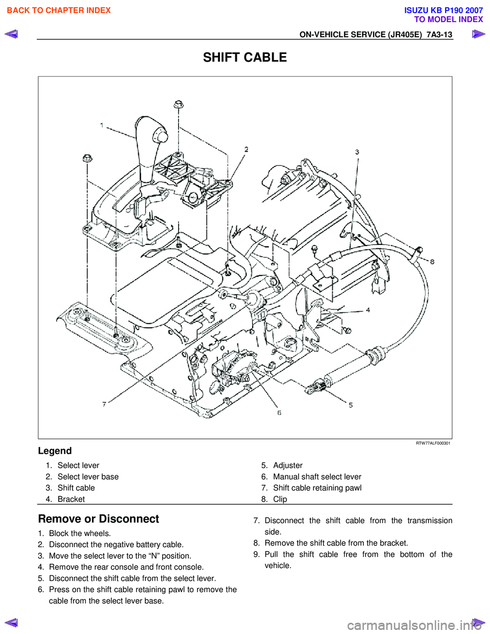
SHIFT CABLE
RTW 77ALF000301
Legend
1. Select lever
2. Select lever base
3. Shift cable
4. Bracket
5. Adjuster
6. Manual shaft select lever
7. Shift cable retaining pawl
8. Clip
Remove or Disconnect
1. Block the wheels.
2. Disconnect the negative battery cable.
3. Move the select lever to the “N” position.
4. Remove the rear console and front console.
5. Disconnect the shift cable from the select lever.
6. Press on the shift cable retaining pawl to remove the cable from the select lever base.
7. Disconnect the shift cable from the transmission
side.
8. Remove the shift cable from the bracket.
9. Pull the shift cable free from the bottom of the vehicle.
BACK TO CHAPTER INDEX
TO MODEL INDEX
ISUZU KB P190 2007
Page 4468 of 6020
7A3-14 ON-VEHICLE SERVICE (JR405E)
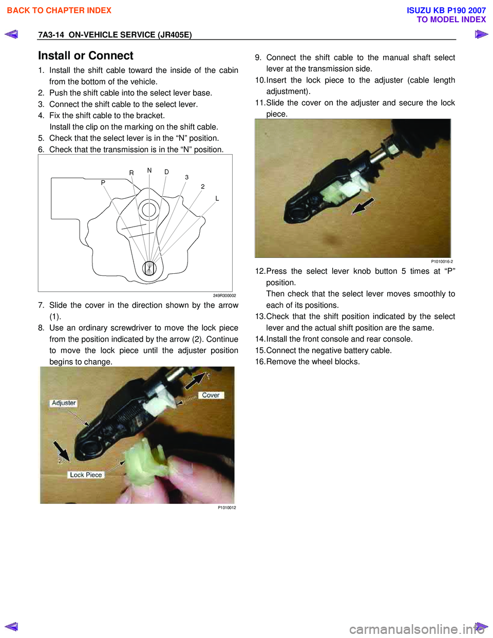
Install or Connect
1. Install the shift cable toward the inside of the cabin
from the bottom of the vehicle.
2. Push the shift cable into the select lever base.
3. Connect the shift cable to the select lever.
4. Fix the shift cable to the bracket.
Install the clip on the marking on the shift cable.
5. Check that the select lever is in the “N” position.
6. Check that the transmission is in the “N” position.
249R300002
7. Slide the cover in the direction shown by the arrow
(1).
8. Use an ordinary screwdriver to move the lock piece from the position indicated by the arrow (2). Continue
to move the lock piece until the adjuster position
begins to change.
P1010012
9. Connect the shift cable to the manual shaft select
lever at the transmission side.
10. Insert the lock piece to the adjuster (cable length adjustment).
11. Slide the cover on the adjuster and secure the lock piece.
P1010016-2
12. Press the select lever knob button 5 times at “P”position.
Then check that the select lever moves smoothly to each of its positions.
13. Check that the shift position indicated by the select lever and the actual shift position are the same.
14. Install the front console and rear console.
15. Connect the negative battery cable.
16. Remove the wheel blocks.
BACK TO CHAPTER INDEX
TO MODEL INDEX
ISUZU KB P190 2007
Page 4469 of 6020
ON-VEHICLE SERVICE (JR405E) 7A3-15
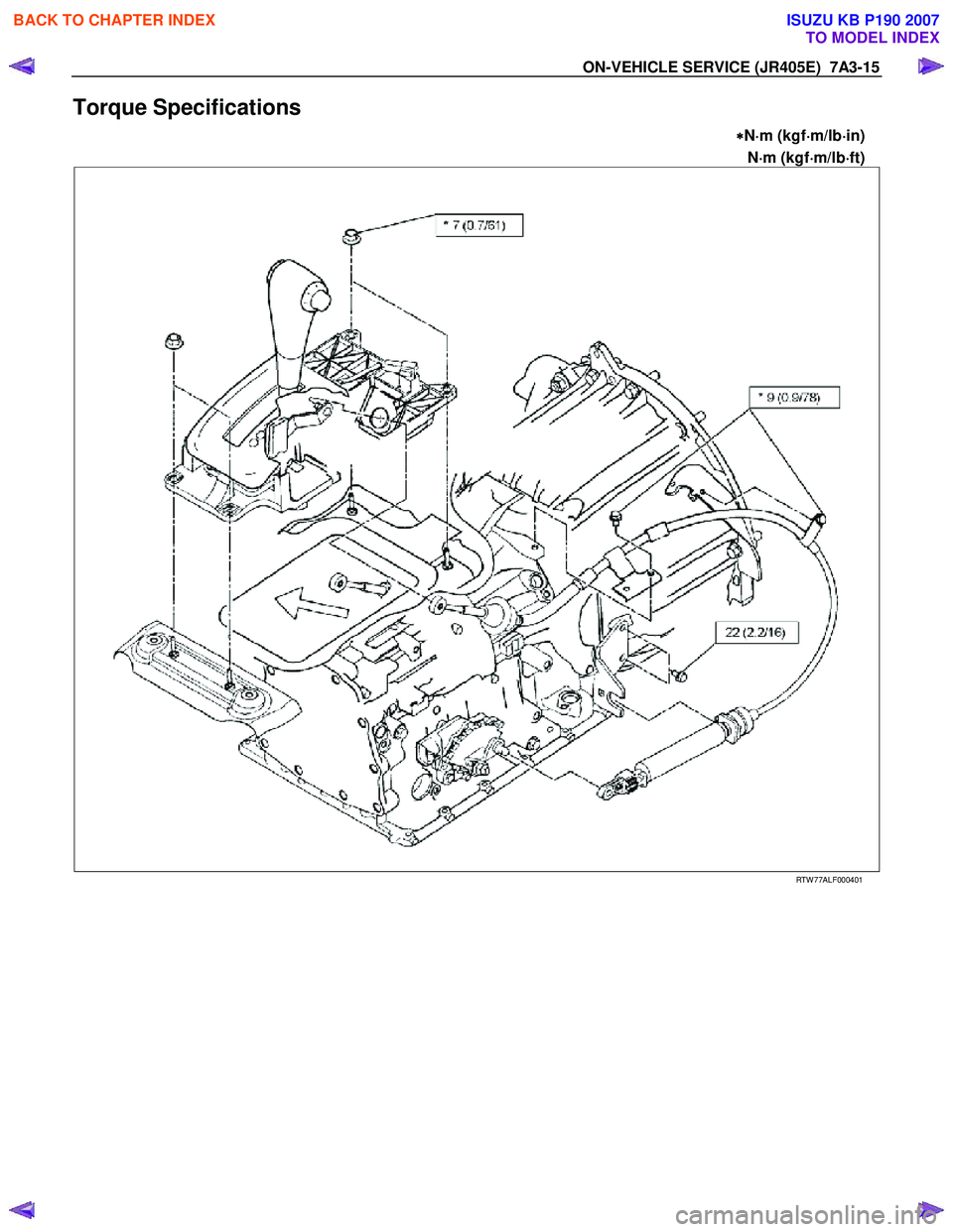
Torque Specifications
∗
∗∗
∗
N ⋅
⋅⋅
⋅
m (kgf ⋅
⋅⋅
⋅
m/lb ⋅
⋅⋅
⋅
in)
N ⋅
⋅⋅
⋅
m (kgf ⋅
⋅⋅
⋅
m/lb ⋅
⋅⋅
⋅
ft)
RTW 77ALF000401
BACK TO CHAPTER INDEX
TO MODEL INDEX
ISUZU KB P190 2007
Page 4470 of 6020

7A3-16 ON-VEHICLE SERVICE (JR405E)
SOLENOIDS, OIL PRESSURE SWITCH AND OIL TEMPERATURE
SENSOR
244L300003
Legend
1. High clutch oil pressure switch connector
(wire color: Gray)
2. 2-4 brake oil pressure switch connector
(wire color: Brown)
3. Low and reverse brake oil pressure switch connector (wire color: W hite)
4. Low and reverse brake duty solenoid connector
(wire color: Pink and W hite)
5. High clutch duty solenoid connector
(wire color: Green and Gray)
6. Lock-up duty solenoid connector
(wire color: Yellow and Black)
7. 2-4 brake duty solenoid connector
(wire color: Blue and Brown)
8. Low clutch duty solenoid connector
(wire color: Orange and Black)
9. Line pressure solenoid connector
(wire color: Pink)
BACK TO CHAPTER INDEX
TO MODEL INDEX
ISUZU KB P190 2007