ISUZU KB P190 2007 Workshop Repair Manual
Manufacturer: ISUZU, Model Year: 2007, Model line: KB P190, Model: ISUZU KB P190 2007Pages: 6020, PDF Size: 70.23 MB
Page 461 of 6020

REAR AXLE 4B-17
8. Certainly install new snap ring, use snap ring
pliers. W hen transform or damage, replace ne
w
one.
RTW 34BMH000101
Legend
1. Snap ring
2. Crevice
3. Retainer (with ABS)
Retainer (without ABS)
9. Insert a shim of sufficient thickness between
snap ring and end of retainer.
Standard 0 − 0.2 mm (0 − 0.008 in)
Crevice is measured using thickness gauge, and
when crevice exceeds 0.2 mm (0.008 in), it
adjusts so that is may become 0.2 mm (0.008 in)
or less using shim.
Shim Pats No. Thickness
1 9-41519110- ∗ 0.18 mm (0.0071 in)
2 8-97130387- ∗ 0.50 mm (0.0197 in)
Crevice No. of shim Total
mm (in)
1 2 mm (in)
1.0(0.0394) 2 1.00(0.0394)
0.9(0.0354) 2 1 0.86(0.0339)
0.8(0.0315) 1 1 0.68(0.0268)
0.7(0.0276) 1 1 0.68(0.0268)
0.6(0.0236) 1 0.50(0.0197)
0.5(0.0197) 1 0.50(0.0197)
0.4(0.0157) 2 0.36(0.0142)
0.3(0.0118) 1 0.18(0.0071)
0.2(0.0079) 1 0.18(0.0071)
10. Install axle shaft assembly in rear axle case
assembly.
a. Clean the mating surface of axle case and bearing holder.
b. Apply Three Bond 1215 (TB1215) o
r
equivalent on the surface of axle case
assembly.
Note:
When inserting an axle shaft, it inserts so that an
oil seal may not be damaged.
11. Install and tighten bearing holder fixing nut to the specified torque.
Torque : 84 N ⋅m (8.6 kgf ⋅m/62 lb ⋅ft)
12. Install wheel cylinder and tighten the bolt to the specified torque.
Torque : 9 N ⋅m (0.9 kgf ⋅m/78 lb ⋅in)
13. Install parking brake outer cable in back plate and inner cable in parking brake lever.
BACK TO CHAPTER INDEX
TO MODEL INDEX
ISUZU KB P190 2007
Page 462 of 6020

4B-18 REAR AXLE
14. Install shoe assembly with adjuster lever, shoe
assembly with parking brake lever and spring.
15. Install return spring.
16. Install shoe clamp spring and tension pin.
305R300001
Legend
1. Tension Pin
2. Shoe Clamp Spring
3. Return Spring
4. Shoe Assembly with Parking Brake Lever
5. Shoe Assembly with Adjuster Lever
6. Spring
7. Parking Brake Cable
8. Adjuster
9. Parking Brake Lever
10. Adjuster Spring
11. Adjuster Lever
12. W heel Cylinder
13. Back plate
BACK TO CHAPTER INDEX
TO MODEL INDEX
ISUZU KB P190 2007
Page 463 of 6020

REAR AXLE 4B-19
17. Install brake pipe and ABS sensor and tighten it
to the specified torque.
Torque : ABS Sensor 8 N ⋅m (0.8 kgf ⋅m/69 lb ⋅in)
Brake Pipe 16 N ⋅m (1.6 kgf ⋅m/12 lb ⋅ft)
420R30003
18. Bleed brake pipe at the wheel cylinder. (Refer to
the section “Power-assisted Brake System”)
19. Install brake drum.
• Install propeller shaft. (Refer to Section “Rea
r
Propeller Shaft”.)
• Refill differential oil.
• Install wheel and tire.
• Lower vehicle.
BACK TO CHAPTER INDEX
TO MODEL INDEX
ISUZU KB P190 2007
Page 464 of 6020

4B-20 REAR AXLE
DIFFERENTIAL ASSEMBLY
Disassemble View
Legend
1. Bolt
2. Bearing Cap
3. Differential Cage Assembly
4. Side Bearing Outer Race
5. Side Bearing
6. Adjust Shim
7. Flange Nut
8. Flange Assembly
9. Drive Pinion Shaft Assembly
415RY00005
10. Collapsible Spacer
11. Inner Bearing
12. Adjust Shim
13. Oil Seal
14. Outer Bearing
15. Inner Bearing Outer Race
16. Outer Bearing Outer Race
17. Differential Carrier
BACK TO CHAPTER INDEX
TO MODEL INDEX
ISUZU KB P190 2007
Page 465 of 6020

REAR AXLE 4B-21
Disassembly
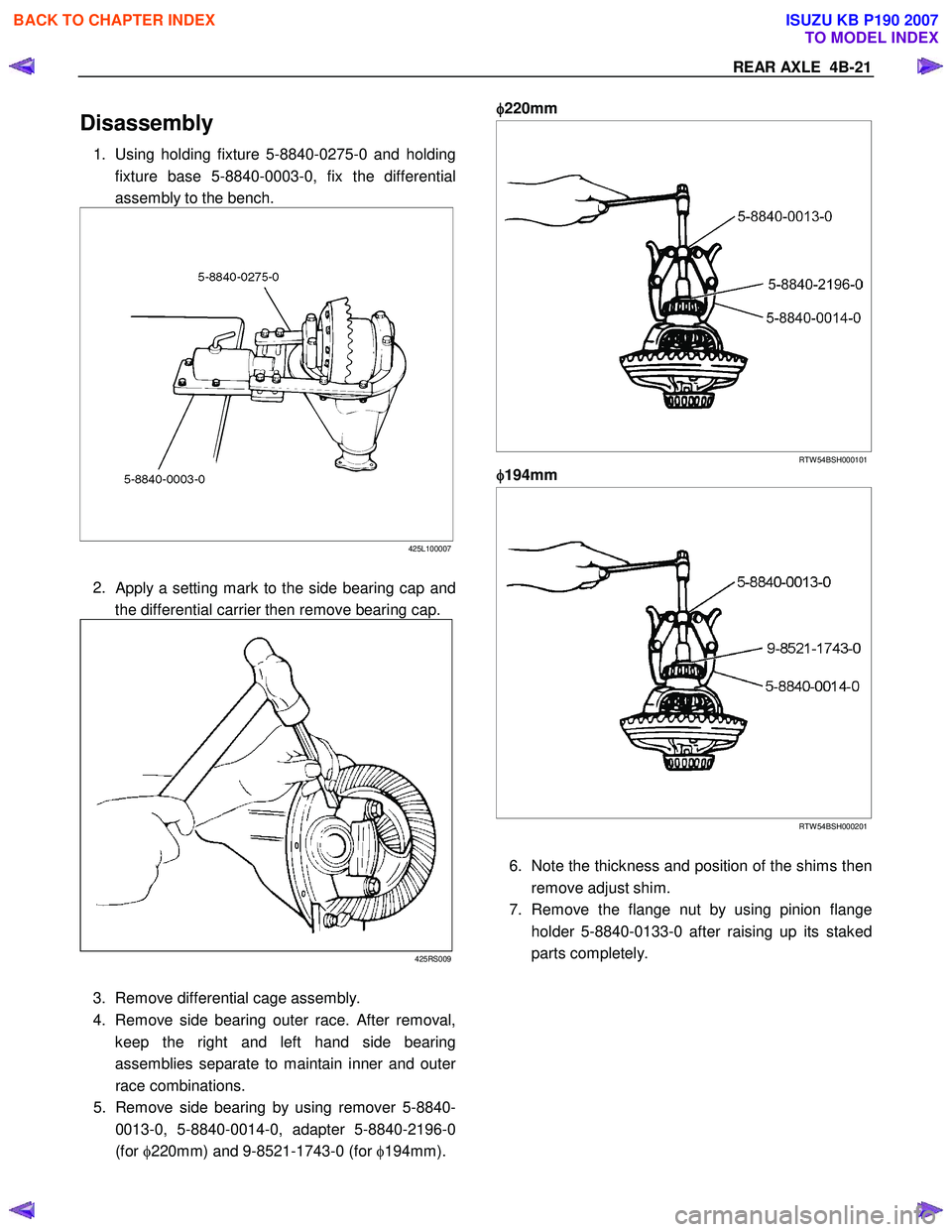
1. Using holding fixture 5-8840-0275-0 and holding
fixture base 5-8840-0003-0, fix the differential
assembly to the bench.
425L100007
2.
Apply a setting mark to the side bearing cap and
the differential carrier then remove bearing cap.
425RS009
3. Remove differential cage assembly.
4. Remove side bearing outer race. After removal,
keep the right and left hand side bearing
assemblies separate to maintain inner and oute
r
race combinations.
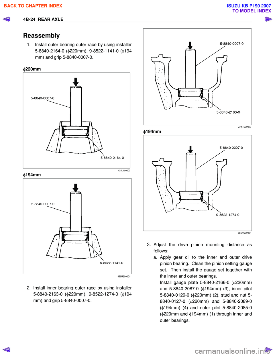
5. Remove side bearing by using remover 5-8840-
0013-0, 5-8840-0014-0, adapter 5-8840-2196-0
(for φ220mm) and 9-8521-1743-0 (for φ194mm).
φ
φφ
φ
220mm
RTW 54BSH000101
φ
φφ
φ
194mm
RTW 54BSH000201
6. Note the thickness and position of the shims then
remove adjust shim.
7. Remove the flange nut by using pinion flange holder 5-8840-0133-0 after raising up its staked
parts completely.
BACK TO CHAPTER INDEX
TO MODEL INDEX
ISUZU KB P190 2007
Page 466 of 6020

4B-22 REAR AXLE
415RW 040
8. Removed flange assembly.
9. Remove the drive pinion assembly using a soft metal rod and a hammer.
425RY005
10. Remove collapsible spacer.
11. Remove the inner bearing by using separator 5- 8840-2197-0 ( φ220mm) and 5-8840-0015-0
( φ 194mm) .
φ
φφ
φ
220mm
RTW 54BSH000601
φ
φφ
φ
194mm
415R300001
12. Remove adjust shim.
13. Remove oil seal.
14. Remove outer bearing.
BACK TO CHAPTER INDEX
TO MODEL INDEX
ISUZU KB P190 2007
Page 467 of 6020

REAR AXLE 4B-23
15. Remove the inner bearing outer race (1) and the
outer bearing outer race (2) by using a brass ba
r
and a hammer.
425RS014
425RS015
BACK TO CHAPTER INDEX
TO MODEL INDEX
ISUZU KB P190 2007
Page 468 of 6020

4B-24 REAR AXLE
Reassembly
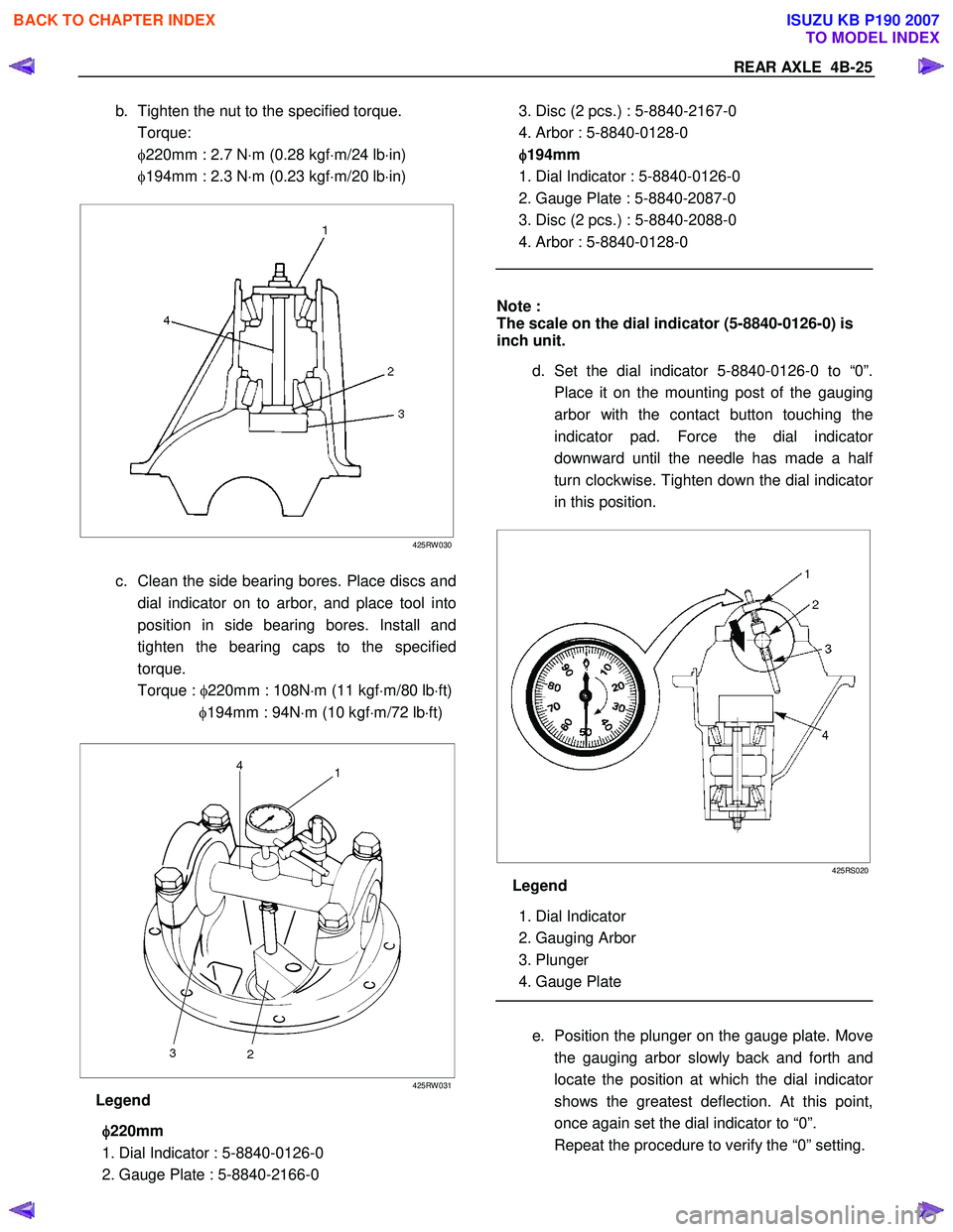
1. Install outer bearing outer race by using installer
5-8840-2164-0 (φ220mm), 9-8522-1141-0 ( φ194
mm) and grip 5-8840-0007-0.
φ
φφ
φ
220mm
425L100002
φ
φφ
φ
194mm
425R300001
2. Install inner bearing outer race by using installe
r
5-8840-2163-0 ( φ220mm), 9-8522-1274-0 ( φ194
mm) and grip 5-8840-0007-0.
425L100003
φ
φφ
φ
194mm
425R300002
3.
Adjust the drive pinion mounting distance as
follows:
a.
Apply gear oil to the inner and outer drive
pinion bearing. Clean the pinion setting gauge
set. Then install the gauge set together with
the inner and outer bearings.
Install gauge plate 5-8840-2166-0 ( φ220mm)
and 5-8840-2087-0 ( φ194mm) (3), inner pilot
5-8840-0129-0 ( φ220mm) (2), stud and nut 5-
8840-0127-0 ( φ220mm) and 5-8840-2089-0
( φ 194mm) (4) and outer pilot 5-8840-2085-0
( φ 220mm and φ194mm) (1) through inner and
outer bearings.
BACK TO CHAPTER INDEX
TO MODEL INDEX
ISUZU KB P190 2007
Page 469 of 6020

REAR AXLE 4B-25
b. Tighten the nut to the specified torque.
Torque:
φ220mm : 2.7 N ⋅m (0.28 kgf ⋅m/24 lb ⋅in)
φ194mm : 2.3 N ⋅m (0.23 kgf ⋅m/20 lb ⋅in)
425RW 030
c. Clean the side bearing bores. Place discs and
dial indicator on to arbor, and place tool into
position in side bearing bores. Install and
tighten the bearing caps to the specified
torque.
Torque : φ220mm : 108N ⋅m (11 kgf ⋅m/80 lb ⋅ft)
φ194mm : 94N ⋅m (10 kgf ⋅m/72 lb ⋅ft)
425RW 031
Legend
φ
φφ
φ
220mm
1. Dial Indicator : 5-8840-0126-0
2. Gauge Plate : 5-8840-2166-0
3. Disc (2 pcs.) : 5-8840-2167-0
4. Arbor : 5-8840-0128-0
φ
φφ
φ
194mm
1. Dial Indicator : 5-8840-0126-0
2. Gauge Plate : 5-8840-2087-0
3. Disc (2 pcs.) : 5-8840-2088-0
4. Arbor : 5-8840-0128-0
Note :
The scale on the dial indicator (5-8840-0126-0) is
inch unit.
d. Set the dial indicator 5-8840-0126-0 to “0”.
Place it on the mounting post of the gauging
arbor with the contact button touching the
indicator pad. Force the dial indicato
r
downward until the needle has made a hal
f
turn clockwise. Tighten down the dial indicato
r
in this position.
425RS020
Legend
1. Dial Indicator
2. Gauging Arbor
3. Plunger
4. Gauge Plate
e. Position the plunger on the gauge plate. Move
the gauging arbor slowly back and forth and
locate the position at which the dial indicato
r
shows the greatest deflection. At this point,
once again set the dial indicator to “0”.
Repeat the procedure to verify the “0” setting.
BACK TO CHAPTER INDEX
TO MODEL INDEX
ISUZU KB P190 2007
Page 470 of 6020

4B-26 REAR AXLE
425RS02
f.
After the ZERO setting is obtained, rotate the
gauging arbor until the dial indicator rod does
not touch the gauging plate. Record the
number the dial indicator needle points.
425RS022
Legend
1. Example=Dial indicator reading on 0.085
g. Record the pinion depth code on the head o
f
the drive pinion. The number indicates a
necessary change in the pinion mounting
distance. A plus number indicates the need
for a greater mounting distance (which can be
achieved by decreasing the shim thickness).
A
minus number indicates the need for a smalle
r
mounting distance (which can be achieved b
y
increasing the shim thickness). If examination
reveals pinion depth code “0”, the pinion is
“nominal”.
425RS023
BACK TO CHAPTER INDEX
TO MODEL INDEX
ISUZU KB P190 2007