check engine ISUZU KB P190 2007 Workshop Repair Manual
[x] Cancel search | Manufacturer: ISUZU, Model Year: 2007, Model line: KB P190, Model: ISUZU KB P190 2007Pages: 6020, PDF Size: 70.23 MB
Page 2124 of 6020

6C-6 ENGINE FUEL (C24SE)
Fuel Filter
Inspection
1. Replace the fuel filter if the fuel leaks from fuel filter
body or if the fuel filter body itself is damaged.
2. Replace the filter if it is clogged with dirt o
r
sediment.
Installation
1. Install the filter to holder from fuel tank front side.
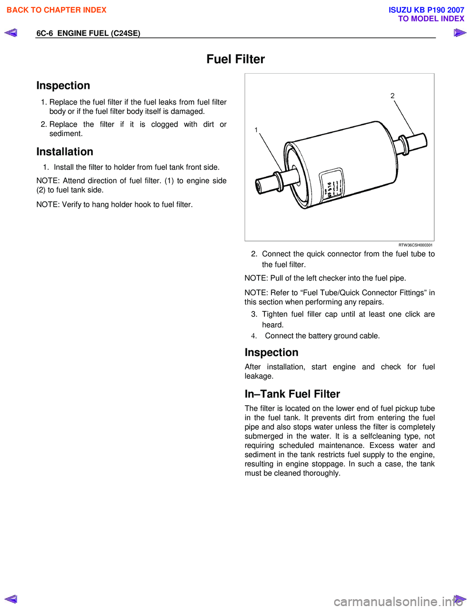
NOTE: Attend direction of fuel filter. (1) to engine side
(2) to fuel tank side.
NOTE: Verify to hang holder hook to fuel filter.
RTW 36CSH000301
2. Connect the quick connector from the fuel tube to
the fuel filter.
NOTE: Pull of the left checker into the fuel pipe.
NOTE: Refer to “Fuel Tube/Quick Connector Fittings” in
this section when performing any repairs.
3. Tighten fuel filler cap until at least one click are heard.
4. Connect the battery ground cable.
Inspection
After installation, start engine and check for fuel
leakage.
In–Tank Fuel Filter
The filter is located on the lower end of fuel pickup tube
in the fuel tank. It prevents dirt from entering the fuel
pipe and also stops water unless the filter is completel
y
submerged in the water. It is a selfcleaning type, not
requiring scheduled maintenance. Excess water and
sediment in the tank restricts fuel supply to the engine,
resulting in engine stoppage. In such a case, the tank
must be cleaned thoroughly.
BACK TO CHAPTER INDEX
TO MODEL INDEX
ISUZU KB P190 2007
Page 2125 of 6020

ENGINE FUEL (C24SE) 6C-7
Fuel Pump Flow Test
If reduction of fuel supply is suspected, perform the
following checks.
1. Make sure that there is fuel in the tank.
2. W ith the engine running, check the fuel feed pipe and hose from fuel tank to injector for evidence o
f
leakage. Retighten, if pipe or hose connection is
loose. Also, check pipes and hoses for squashing
or clogging.
3. Insert the hose from fuel feed pipe into a clean container, and check for fuel pump flow rate.
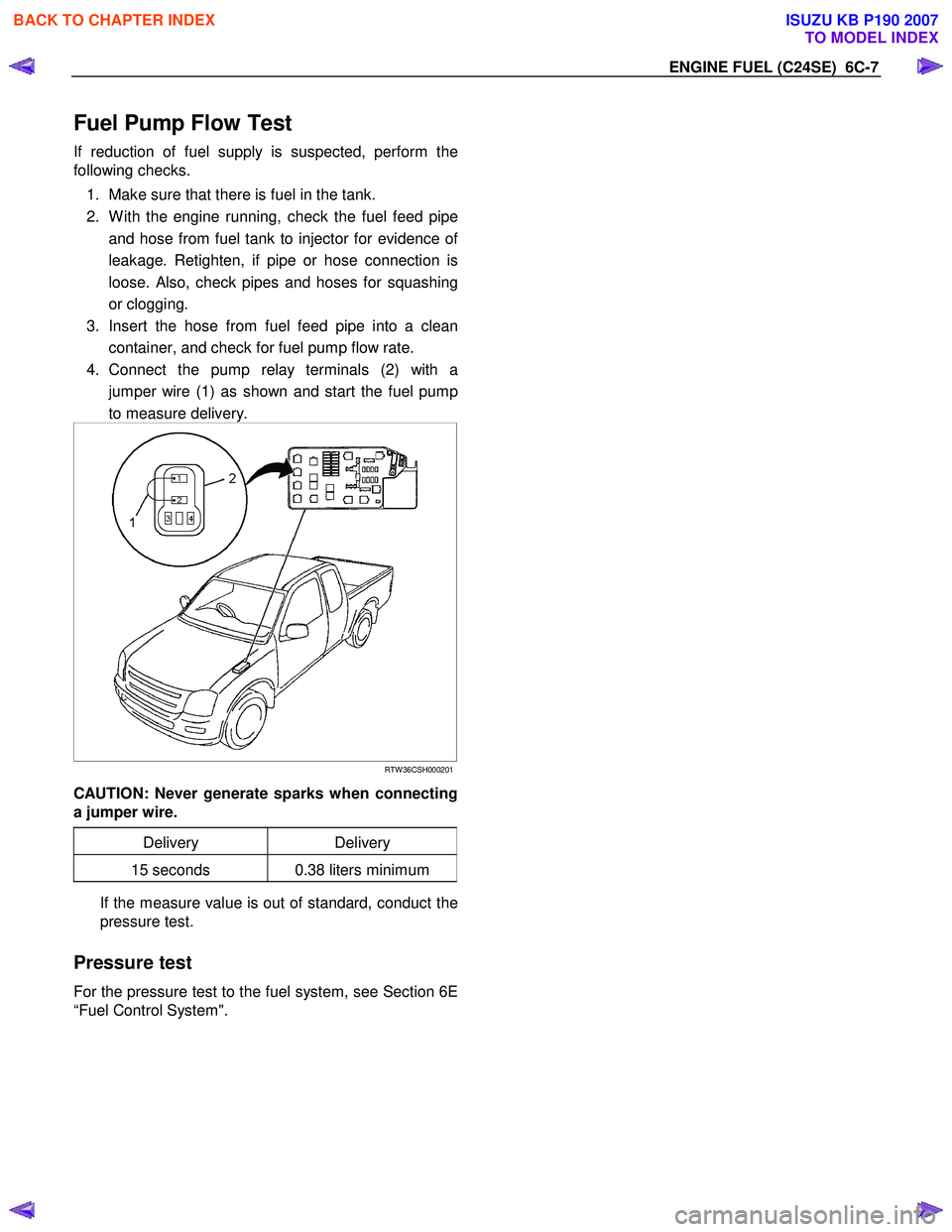
4. Connect the pump relay terminals (2) with a jumper wire (1) as shown and start the fuel pump
to measure delivery.
RTW 36CSH000201
CAUTION: Never generate sparks when connecting
a jumper wire.
Delivery Delivery
15 seconds 0.38 liters minimum
If the measure value is out of standard, conduct the
pressure test.
Pressure test
For the pressure test to the fuel system, see Section 6E
“Fuel Control System".
BACK TO CHAPTER INDEX
TO MODEL INDEX
ISUZU KB P190 2007
Page 2126 of 6020

6C-8 ENGINE FUEL (C24SE)
Fuel Pump
Fuel Pump and Associated Parts
RTW 46FMF000401
Legend (6) Fuel Tube/Quick Connector
(1) Fuel Feed Port (7) Retainer Ring (Fuel Pump Lock)
(2) Fuel Return Port (8) Seal; Fuel Pump
(3) Fuel Emission Port (9) Fuel Tank Assembly
(4) Fuel Pump and Sender Assembly (10) Evapo Tube/Quick Connector
(5) Connector; Fuel Feed Pump & Sender
Removal
CAUTION: When repair to the fuel system has been
completed, start engine and check the fuel system
for loose connection or leakage. For the fuel system
diagnosis, see Section “Driveability and Emission".
1. Remove fuel tank assembly (9). Refer to “Fuel Tank Removal" in this section.
2. Disconnect the quick connector (6) into the fuel tube from fuel pump.
3. Disconnect the quick connector (10) into the evapo tube from fuel pump.
BACK TO CHAPTER INDEX
TO MODEL INDEX
ISUZU KB P190 2007
Page 2127 of 6020

ENGINE FUEL (C24SE) 6C-9
3. Remove the retainer ring (7) from the fuel tank
with the removal tool 5-8840-2602-0.
140R100035
4. Remove slowly the fuel pump (4) from the fuel
tank as no bend float arm.
NOTE: Cover opening for the fuel pump on fuel tank to
prevent any dust enthering.
5. Discard fuel pump seal (8) because it cannot be
reusable.
Installation
1. Clean the seal surface of the fuel tank and the fuel pump.
NOTE: If there is dust on the seal surface, it becomes
cause of fuel leak.
2. Install the new fuel pump seal (8) to opening of the fuel tank as along the groove.
3. Install slowly the fuel pump (4) into the fuel tank as no bend float arm.
4. Set flange of the fuel pump on fuel pump seal as
mating convexity of the fuel pump and reentrant o
f
the fuel tank.
5. Lock slowly the retainer ring (7) to the fuel tank
with the remover tool 5-8840-2602-0.
6. Connector the quick conector (10) into the evapo tube to fuel pump.
7. Connect the quick connector (6) into the fuel tube
to fuel pump.
NOTE: Pull off the left ckecker into the fuel pipe.
NOTE: Refer to “Fuel Tube/Quick Connector Fittings” in
this section when performing any repairs.
8. Check leak.
Methed of leak check.
(1) Plug end of quick connector and breather hose
(Pull off the breather hose from fuel tank) and
tighten fuel filler cap until at least one click are
heard.
(2)
Apply water soap around the fuel pump seal
area.
(3) Pressure air into the fuel tank from end o
f
breather pipe at 5psi (34.3 kPa/2.8kgf/cm2)
over 15 seconds.
(4) Verify no bubbles around the fuel pump seal
area.
8. Install the fuel tank assembly (9).
NOTE: Refer to “Install the fuel tank” in this section.
BACK TO CHAPTER INDEX
TO MODEL INDEX
ISUZU KB P190 2007
Page 2132 of 6020

6C-14 ENGINE FUEL (C24SE)
Removal
CAUTION: When repair to the fuel system has been
completed, start engine and check the fuel system
for loose connection or leakage. For the fuel system
diagnosis, see Section “Driveability and Emission".
1. Disconnect battery ground cable.
2. Loosen slowly the fuel filler cap.
NOTE: To prevent spouting out fuel to change the
pressure in the fuel tank.
NOTE: Cover opening of the filler neck to prevent an
y
dust entering.
3. Jack up the vehicle.
4. Support underneath of the fuel tank with a lifter.
5. Remove the inner liner of the wheel house on rea
r
left side.
6. Remove fasten bolt to the filler neck from the body.
7. Disconnect the quick connector (8) into the fuel
tube from the fuel pipe and the evapo tube from
evapo joint connector.
NOTE: Cover the quick connector to prevent any dust
entering and fuel leaking.
NOTE: Refer to “Fuel Tube/Quick Connector Fittings” in
this section when performing any repairs.
8. Remove fasten bolt (1) to the tank band and the tank band (2).
9. Disconnect the pump and sender connector on the
fuel pump and remove the harness from weld clip
on the fuel tank.
10. Lower the fuel tank (6).
NOTE: W hen the fuel tank is lowered from the vehicle,
don’t scratch each hose and tube by around other pars.
Installation
1. Rise the fuel tank into position.
NOTE: Ensure hoses and tubes do not foul on othe
r
component. 2. Connect the pump and sender connector to the
fuel pump and install harness to into the plastic clip
welded to the top of the fuel tank..
NOTE: The connector must be certainly connected
against stopper.
Ensure tank band anchor mates with guide hole on
frame.
3. Install the tank band to fasten bolt.
Torque: 68 N ⋅
⋅⋅
⋅
m (6.9kg ⋅
⋅⋅
⋅
m/50 lb ft)
NOTE: The anchor of the tank band must be certainl
y
installed to guide hole on frame. 4. Connect the quick connector from the fuel tube to
the fuel pipe and the evapo tube from evapo joint
connector.
NOTE: Pull off the left checker into the fuel pipe.
NOTE: Refer to “Fuel Tube/Quick Connector Fittings” in
this section when performing any repairs.
5. Install the filler neck to the body by bolt.
6. Install the inner liner of the wheel house on rea
r
side.
7. Remove lifter to support underneath of the fuel tank.
8. Put back the vehicle.
9. Tigten the filler cap until at least three clicks are
heard.
10. Connect the battery ground cable.
BACK TO CHAPTER INDEX
TO MODEL INDEX
ISUZU KB P190 2007
Page 2140 of 6020

ENGINE ELECTRICAL 6D1-3
Diagnosis
1. Visual Inspection
Inspect the battery for obvious physical damage, such as a
cracked or broken case, which would permit electrolyte loss.
Replace the battery if obvious physical damage is discovered
during inspection.
Check for any other physical damage and correct it as
necessary.
2. Hydrometer Check
3. Fluid Level Check
The fluid level should be between the upper level line (2) and
lower lever line (3) on side of battery.
a. CORRECT FLUID LEVEL - Charge the battery.
b. BELOW LOW ER LEVEL - Replace battery.
4. Voltage Check
1. Put voltmeter test leads to battery terminals. a. VOLTAGE IS 12.4V OR ABOVE - Go to Step 5.
b. VOLTAGE IS UNDER 12.4V - Go to procedure (2) below.
2. Determine fast charge amperage from specification.
(See Main Data and Specifications in this section).
Fast charge battery for 30 minutes at amperage rate no higher than specified value.
Take voltage and amperage readings after charge. a. VOLTAGE IS ABOVE 16V AT BELOW 1/3 OF AMPERAGE RATE - Replace battery.
b. VOLTAGE IS ABOVE 16V AT ABOVE 1/3 OF AMPERAGE RATE - Drop charging voltage to 15V and
charge for 10 - 15 hours. Then go to Step 5.
c. VOLTAGE IS BETW EEN 12V AND 16V - Continue charging at the same rate for an additional 3-1/2 hours.
Then go to Step 5.
d. VOLTAGE BELOW 12V - Replace Battery.
BACK TO CHAPTER INDEX
TO MODEL INDEX
ISUZU KB P190 2007
Page 2146 of 6020

IGNITION SYSTEM 6D2-3
Spark Plug
Removal
1. Remove spark plugs.
Inspection and Repair
The spark plug affects entire engine performance and
therefore its inspection is very important.
• Check electrode and insulator for presence of cracks, and
replace if any.
• Check electrode for wear, and replace if necessary.
• Check gasket for damage, and replace if necessary.
• Measure insulation resistance with an ohmmeter, and
replace if faulty.
• Adjust spark plug gap to 1.0 - 1.1 mm (0.027 in) - 0.8 mm
(0.031 in).
• Check fuel and electrical systems if spark plug is extremely
dirty.
• Use spark plugs having low heat value (hot type plug) if fuel
and electrical systems are normal.
• Use spark plugs having high heat value (cold type plug) i
f
insulator and electrode are extremely burned.
Sooty Spark Plugs
Much deposit of carbon or oil on the electrode and insulator of
spark plug reduces the engine performance.
Possible causes:
• Too rich mixture
• Presence of oil in combustion chamber
• Incorrectly adjusted spark plug gap
Burning Electrodes
This fault is characterized by scorched or heavily oxidized
electrode or blistered insulator nose.
Possible causes:
• Too lean mixture
• Improper heat value
Measuring Insulation Resistance
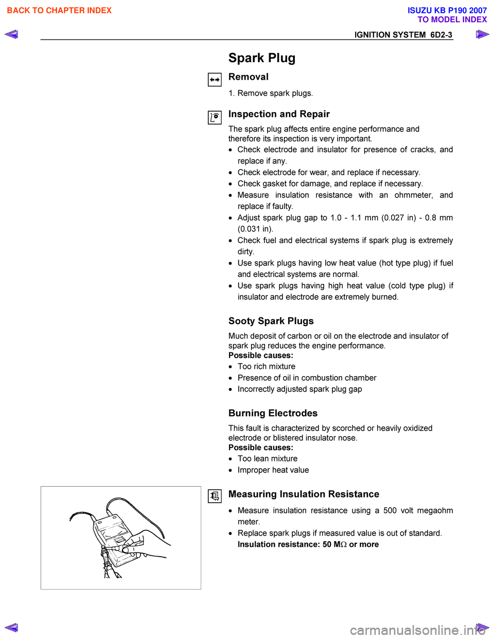
• Measure insulation resistance using a 500 volt megaohm
meter.
• Replace spark plugs if measured value is out of standard.
Insulation resistance: 50 M Ω or more
BACK TO CHAPTER INDEX
TO MODEL INDEX
ISUZU KB P190 2007
Page 2147 of 6020

6D2-4 IGNITION SYSTEM
Cleaning Spark Plugs
• Clean spark plugs with a spark plug cleaner.
• Raise the ground electrode to an angle of 45 to 60 degrees.
if electrode is wet, dry it gefore cleaning.
•
After spark plug is thoroughly cleaned, check insulator for
presence of cracks.
• Clean threads and metal body with a wire brush.
• File the electrode tip if electrode is extremely worn.
• Bend the ground electrode to adjust the spark plug gap.
Installation
1. Spark plugs
• Tighten spark plugs to the specified torque.
Torque: 20 N ⋅m (2.0 kgf ⋅m)
Crankshaft Angle Sensor
Removal
1. Disconnect battery ground cable
2. Disconnect the wiring connector from crankshaft angle sensor.
3. Remove crankshaft angle sensor from cylinder block.
Installation
1. Install crankshaft angle sensor into the cylinder block.
Before installation, apply small amount of engine oil to the O-ring.
Torque: 6 N ⋅m (0.6 kgf ⋅m)
2. Reconnect wiring connector to crankshaft angle sensor.
BACK TO CHAPTER INDEX
TO MODEL INDEX
ISUZU KB P190 2007
Page 2156 of 6020

6D3-8 STARTING AND CHARGING SYSTEM
General On-Vehicle Inspection
The operating condition of charging system is indicated by the
charge warning lamp. The warning lamp comes on when the
starter switch is turned to "ON" position. The charging system
operates normally if the lamp goes off when the engine starts.
If the warning lamp shows abnormality or if undercharged or
overcharged battery condition is suspected, perform diagnosis
by checking the charging system as follows:
1. Check visually the belt and wiring connector.
2. W ith the engine stopped, turn the stator switch to "ON" position and observe the warning lamp.
If lamp does not come on:
Disconnect wiring connector from generator, and ground the terminal "L" on connector side.
If lamp comes on:
Repair or replace the generator.
Generator
Removal
1. Disconnect battery ground cable.
2. Move drive belt tensioner to loose side using wrench then remove drive belt.
3. Disconnect terminal "B" wiring connector and connector.
4. Remove generator assembly.
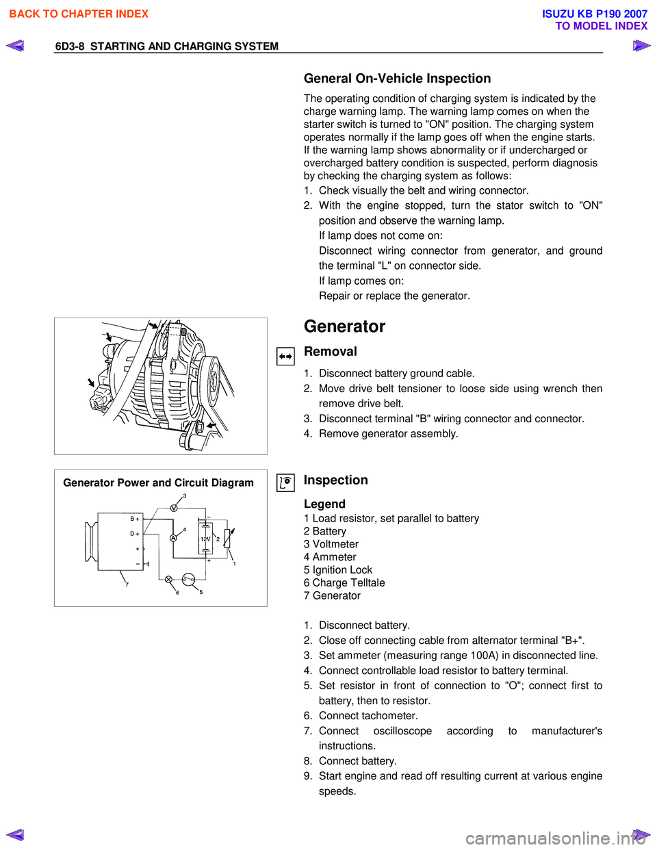
Generator Power and Circuit Diagram
Inspection
Legend
1 Load resistor, set parallel to battery
2 Battery
3 Voltmeter
4 Ammeter
5 Ignition Lock
6 Charge Telltale
7 Generator
1. Disconnect battery.
2. Close off connecting cable from alternator terminal "B+".
3. Set ammeter (measuring range 100A) in disconnected line.
4. Connect controllable load resistor to battery terminal.
5. Set resistor in front of connection to "O"; connect first to battery, then to resistor.
6. Connect tachometer.
7. Connect oscilloscope according to manufacturer's instructions.
8. Connect battery.
9. Start engine and read off resulting current at various engine speeds.
BACK TO CHAPTER INDEX
TO MODEL INDEX
ISUZU KB P190 2007
Page 2167 of 6020

STARTING AND CHARGING SYSTEM 6D3-19
Inspection
Generator
Before any in field testing can be undertaken it is important
that the battery's conditions is established and the terminals
are clean and tight.
Check the condition of the generator drive belt and ensure that
it is adjusted in accordance with the engine manufacturer's
recommnedations.
Battery conditions:
Note: This assessment may be difficult with maintenance free
assemblies.
Test the specific gravity of the individual cells the readings
should be within 10 points of each other, it is recommended
that the average SG should be 1.260 or higher.
A load test should be carried out to determine the ability of the
battery to supply and accept current. This is a good indicator
as to the general condition of the battery.
A load equal to the normal starting current should be placed
across the battery, the duration of this load test should not
exceed 10 seconds, during this time the terminal voltage
across the battery should not drop below 9.6 volts. Observe
each cell for signs of excessive gas liberation, usuall an
indication of cell failure.
If the battery test is clear proceed with the Generator tests as
follows.
Care should be taken when making the following connections.
It is recommended that the battery negative terminal be
disconnected before the test meters are connected, and
reconnecting the negative terminal when the meters are
inserted into the circuit under test. The warning lamp in the D+
circuit should not exceed 2 watts.
Regulating voltage test on the vehicle.
Connect a voltmeter to the generator, the positive lead to the
B+ terminal and the nagative lead to the generator casing.
Select the voltage range to suit the system, i.e. 20v for 12 volt
sysytems or 40v for 24 volt systems. Connect an ammeter in
series with the main output cable from the B+ terminal on the
generator, the range selected must be capable of reading the
maximum output from the generator.
Note the voltmeter reading before starting the engine. This
reading should increase when the engine is running indicating
generator output, start the engine and increase the engine
speed until the generator is running at 4000 rpm, switch on
vehicle loads of 5-10 A is indcated on the ammeter, the
voltmeter shoud read 14.0-14.2 v for a 12 volt system, for a 24
volt system the readings should be 5-10 A and 27.7-28.5 volts.
BACK TO CHAPTER INDEX
TO MODEL INDEX
ISUZU KB P190 2007